front axle NISSAN TIIDA 2011 Service Owner's Guide
[x] Cancel search | Manufacturer: NISSAN, Model Year: 2011, Model line: TIIDA, Model: NISSAN TIIDA 2011Pages: 3787, PDF Size: 78.35 MB
Page 2643 of 3787
FAX-1
DRIVELINE/AXLE
CEF
G H
I
J
K L
M
SECTION FA X
A
B
FA X
N
O P
CONTENTS
FRONT AXLE
SERVICE INFORMATION .. ..........................2
PRECAUTIONS .............................................. .....2
Precaution for Supplemental Restraint System
(SRS) "AIR BAG" and "SEAT BELT PRE-TEN-
SIONER" ............................................................. ......
2
Precaution Necessary for Steering Wheel Rota-
tion After Battery Disconnect ............................... ......
2
General Precautions .................................................3
PREPARATION ...................................................4
Special Service Tool ........................................... ......4
Commercial Service Tool ..........................................4
NOISE, VIBRATION AND HARSHNESS
(NVH) TROUBLESHOOTING .............................
5
NVH Troubleshooting Chart ................................ ......5
FRONT WHEEL HUB AND KNUCKLE .............6
On-Vehicle Inspection and Service ..................... .....6
Removal and Installation ..........................................6
FRONT DRIVE SHAFT ......................................9
On-Vehicle Inspection and Service ..........................9
Removal and Installation (Left Side) .........................9
Removal and Installation (Right Side) .....................10
Disassembly and Assembly (Left Side) ...................13
Disassembly and Assembly (Right Side) .................18
SERVICE DATA AND SPECIFICATIONS
(SDS) .................................................................
25
Wheel Bearing .........................................................25
Drive Shaft ...............................................................25
Dynamic Damper .....................................................25
Boot Bands ..............................................................25
Revision: May 2010 2011 Versa
Page 2647 of 3787
NOISE, VIBRATION AND HARSHNESS (NVH) TROUBLESHOOTINGFAX-5
< SERVICE INFORMATION >
CEF
G H
I
J
K L
M A
B
FA X
N
O P
NOISE, VIBRATION AND HARSHN ESS (NVH) TROUBLESHOOTING
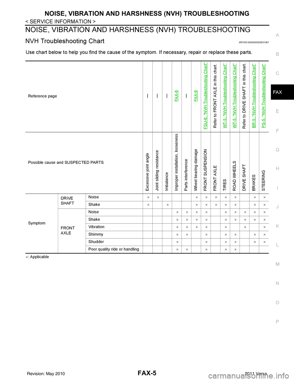
NVH Troubleshooting ChartINFOID:0000000005931067
Use chart below to help you find the cause of the symptom. If necessary, repair or replace these parts.
×: ApplicableReference page
—
—
—
FAX-6—
FAX-6
FSU-6, "
NVH Troubleshooting Chart
"
Refer to FRONT AXLE in this chart.
WT-5, "
NVH Troubleshooting Chart
"
WT-5, "
NVH Troubleshooting Chart
"
Refer to DRIVE SHAFT in this chart. BR-5, "
NVH Troubleshooting Chart
"
PS-5, "
NVH Troubleshooting Chart
"
Possible cause and SUSPECTED PARTS
Excessive joint angle
Joint sliding resistance
Imbalance
Improper installation, looseness
Parts interference
Wheel bearing damage
FRONT SUSPENSION
FRONT AXLE
TIRES
ROAD WHEELS
DRIVE SHAFT
BRAKES
STEERING
SymptomDRIVE
SHAFT
Noise
××××××× ××
Shake × × ××××× ××
FRONT
AXLE Noise
×××× ×××××
Shake ×××× ×××××
Vibration ×××××××
Shimmy ×××××××
Shudder × × ×× ××
Poor quality ride or handling ×××××
Revision: May 2010 2011 Versa
Page 2648 of 3787

FAX-6
< SERVICE INFORMATION >
FRONT WHEEL HUB AND KNUCKLE
FRONT WHEEL HUB AND KNUCKLE
On-Vehicle Inspection and ServiceINFOID:0000000005931068
• Check the axle and suspension parts for excessive play, wear, or damage.
• Shake each front wheel to check for excessive play as shown.
FRONT WHEEL BEARING INSPECTION
• Move wheel hub and bearing assembly in the axial direction by hand. Make sure the axial end play is within
specification.
• Check that the wheel hub bearing operates smoothly.
• Replace the wheel hub assembly if the axial end play exceeds specification, or if the wheel bearing does not turn smoothly. Refer to RAX-6, "
Removal and Installation".
CAUTION:
The wheel hub assembly does not requ ire maintenance. If any of the following symptoms are noted,
replace the wheel hub assembly.
• Growling noise is emitted from the wheel hub bearing during operation.
• Wheel hub bearing drags or turns roughly.
Removal and InstallationINFOID:0000000005931069
COMPONENT
REMOVAL
1. Remove wheel and tire using power tool. Refer to WT-7, "Adjustment".
SMA525A
Axial end play : Refer to FAX-25, "Wheel Bearing"
1. Drive shaft 2. Steering knuckle3. Splash guard
4. Wheel hub and bearing assembly 5. Cotter pin
WDIA0366E
Revision: May 2010 2011 Versa
Page 2652 of 3787
FAX-10
< SERVICE INFORMATION >
FRONT DRIVE SHAFT
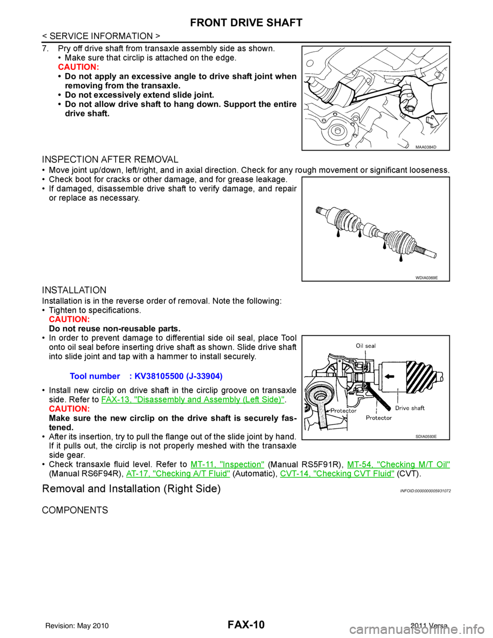
7. Pry off drive shaft from transaxle assembly side as shown.• Make sure that circlip is attached on the edge.
CAUTION:
• Do not apply an excessive angle to drive shaft joint when
removing from the transaxle.
• Do not excessively extend slide joint.
• Do not allow drive shaft to hang down. Support the entire
drive shaft.
INSPECTION AFTER REMOVAL
• Move joint up/down, left/right, and in axial direction. Check for any rough movement or significant looseness.
• Check boot for cracks or other damage, and for grease leakage.
• If damaged, disassemble drive shaft to verify damage, and repair or replace as necessary.
INSTALLATION
Installation is in the reverse order of removal. Note the following:
• Tighten to specifications.CAUTION:
Do not reuse non-reusable parts.
• In order to prevent damage to differential side oil seal, place Tool
onto oil seal before inserting drive shaft as shown. Slide drive shaft
into slide joint and tap with a hammer to install securely.
• Install new circlip on drive shaft in the circlip groove on transaxle side. Refer to FAX-13, "
Disassembly and Assembly (Left Side)".
CAUTION:
Make sure the new circlip on the drive shaft is securely fas-
tened.
• After its insertion, try to pull the flange out of the slide joint by hand. If it pulls out, the circlip is not properly meshed with the transaxle
side gear.
• Check transaxle fluid level. Refer to MT-11, "
Inspection" (Manual RS5F91R), MT-54, "Checking M/T Oil"
(Manual RS6F94R), AT-17, "Checking A/T Fluid" (Automatic), CVT-14, "Checking CVT Fluid" (CVT).
Removal and Installation (Right Side)INFOID:0000000005931072
COMPONENTS
MAA0384D
WDIA0369E
Tool number : KV38105500 (J-33904)
SDIA0593E
Revision: May 2010 2011 Versa
Page 2653 of 3787
FRONT DRIVE SHAFTFAX-11
< SERVICE INFORMATION >
CEF
G H
I
J
K L
M A
B
FA X
N
O P
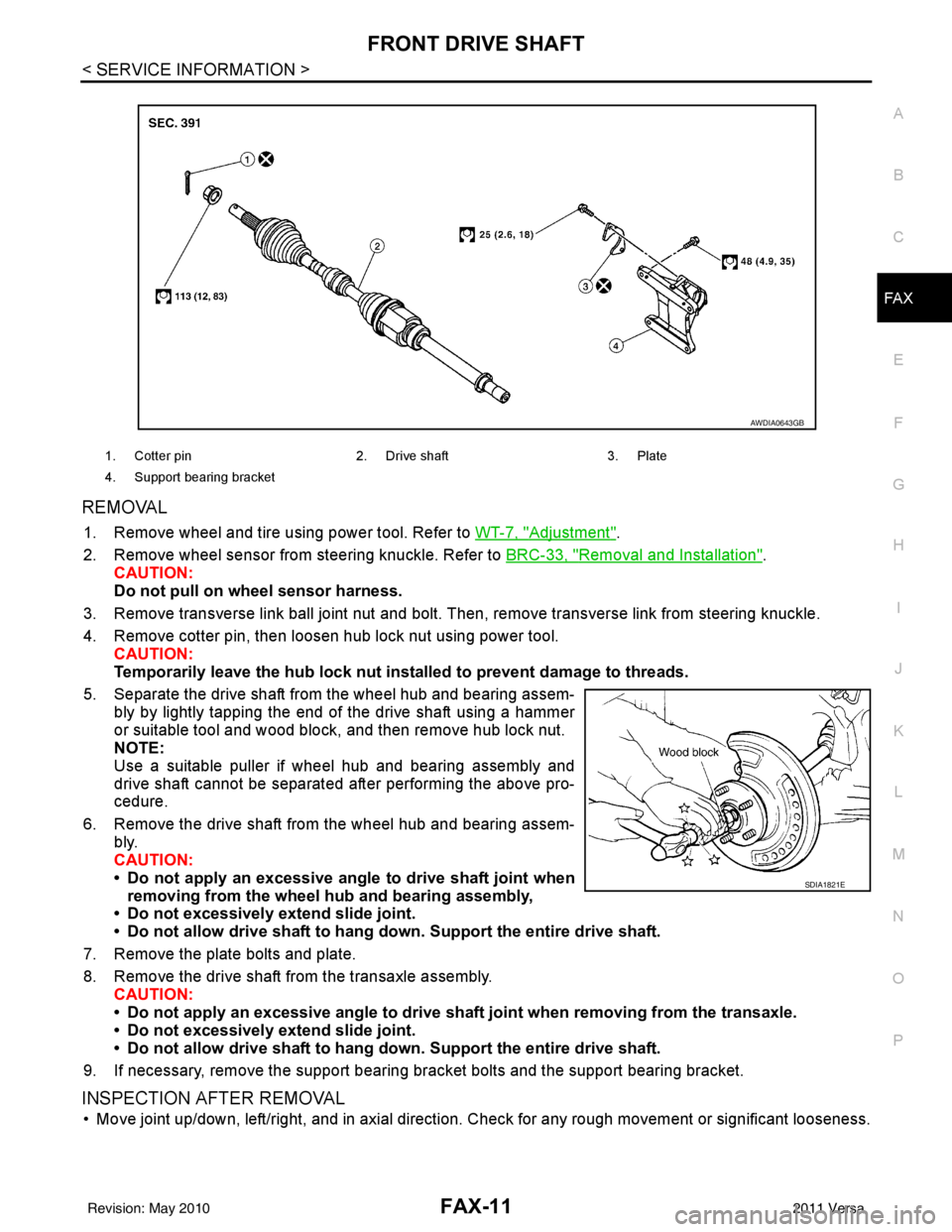
REMOVAL
1. Remove wheel and tire using power tool. Refer to WT-7, "Adjustment".
2. Remove wheel sensor from steering knuckle. Refer to BRC-33, "
Removal and Installation".
CAUTION:
Do not pull on wheel sensor harness.
3. Remove transverse link ball joint nut and bolt. Then, remove transverse link from steering knuckle.
4. Remove cotter pin, then loosen hub lock nut using power tool. CAUTION:
Temporarily leave the hub lock nut inst alled to prevent damage to threads.
5. Separate the drive shaft from the wheel hub and bearing assem- bly by lightly tapping the end of the drive shaft using a hammer
or suitable tool and wood block, and then remove hub lock nut.
NOTE:
Use a suitable puller if wheel hub and bearing assembly and
drive shaft cannot be separated after performing the above pro-
cedure.
6. Remove the drive shaft from the wheel hub and bearing assem- bly.
CAUTION:
• Do not apply an excessive angle to drive shaft joint when
removing from the wheel hub and bearing assembly,
• Do not excessively extend slide joint.
• Do not allow drive shaft to hang do wn. Support the entire drive shaft.
7. Remove the plate bolts and plate.
8. Remove the drive shaft from the transaxle assembly. CAUTION:
• Do not apply an excessive angle to drive shaf t joint when removing from the transaxle.
• Do not excessively extend slide joint.
• Do not allow drive shaft to hang do wn. Support the entire drive shaft.
9. If necessary, remove the support bearing bracket bolts and the support bearing bracket.
INSPECTION AFTER REMOVAL
• Move joint up/down, left/right, and in axial direction. Check for any rough movement or significant looseness.
1. Cotter pin 2. Drive shaft 3. Plate
4. Support bearing bracket
AWDIA0643GB
SDIA1821E
Revision: May 2010 2011 Versa
Page 2654 of 3787
FAX-12
< SERVICE INFORMATION >
FRONT DRIVE SHAFT
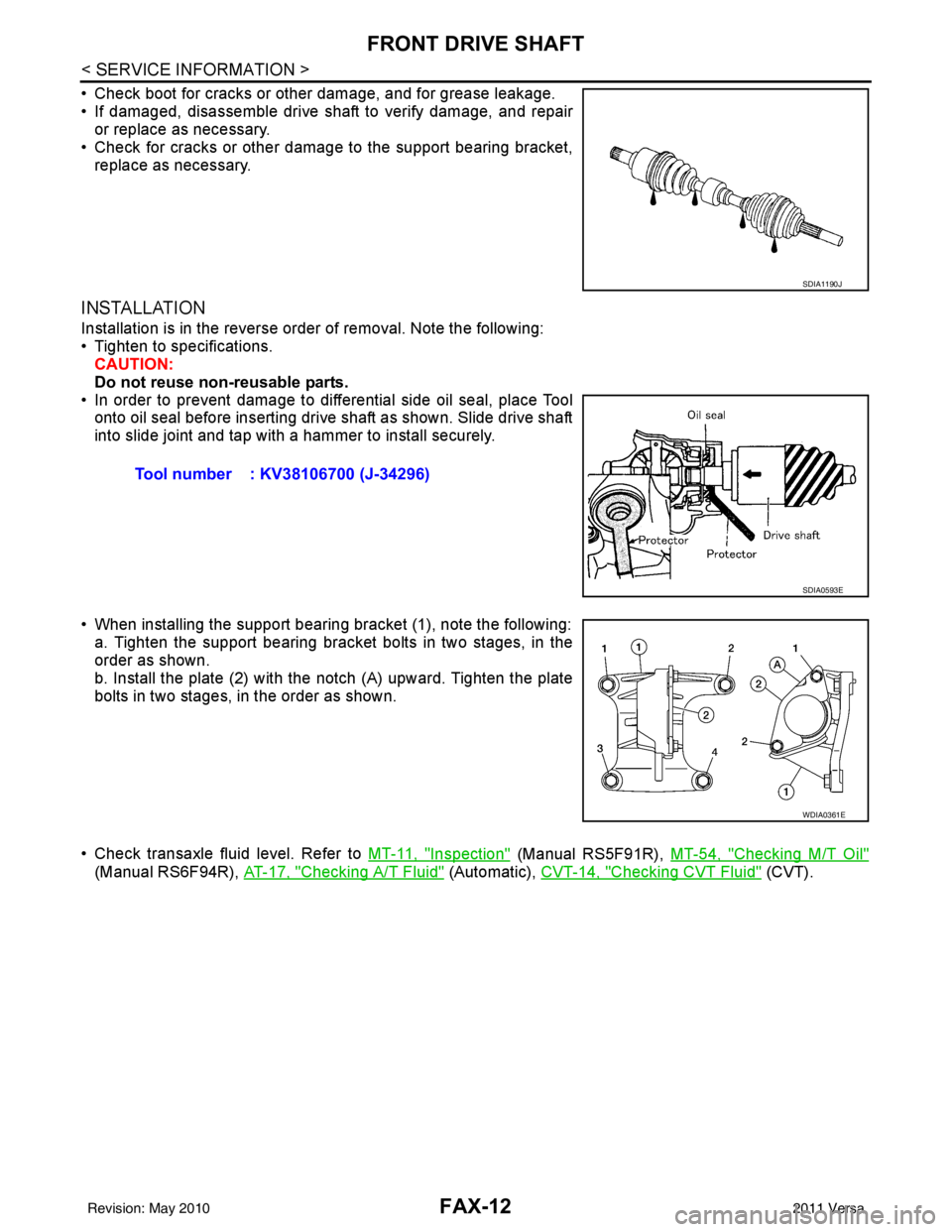
• Check boot for cracks or other damage, and for grease leakage.
• If damaged, disassemble drive shaft to verify damage, and repairor replace as necessary.
• Check for cracks or other damage to the support bearing bracket, replace as necessary.
INSTALLATION
Installation is in the reverse order of removal. Note the following:
• Tighten to specifications.CAUTION:
Do not reuse non-reusable parts.
• In order to prevent damage to differential side oil seal, place Tool onto oil seal before inserting drive shaft as shown. Slide drive shaft
into slide joint and tap with a hammer to install securely.
• When installing the support bearing bracket (1), note the following: a. Tighten the support bearing bracket bolts in two stages, in the
order as shown.
b. Install the plate (2) with the notch (A) upward. Tighten the plate
bolts in two stages, in the order as shown.
• Check transaxle fluid level. Refer to MT-11, "
Inspection" (Manual RS5F91R), MT-54, "Checking M/T Oil"
(Manual RS6F94R), AT-17, "Checking A/T Fluid" (Automatic), CVT-14, "Checking CVT Fluid" (CVT).
SDIA1190J
Tool number : KV38106700 (J-34296)
SDIA0593E
WDIA0361E
Revision: May 2010 2011 Versa
Page 2655 of 3787
FRONT DRIVE SHAFTFAX-13
< SERVICE INFORMATION >
CEF
G H
I
J
K L
M A
B
FA X
N
O P
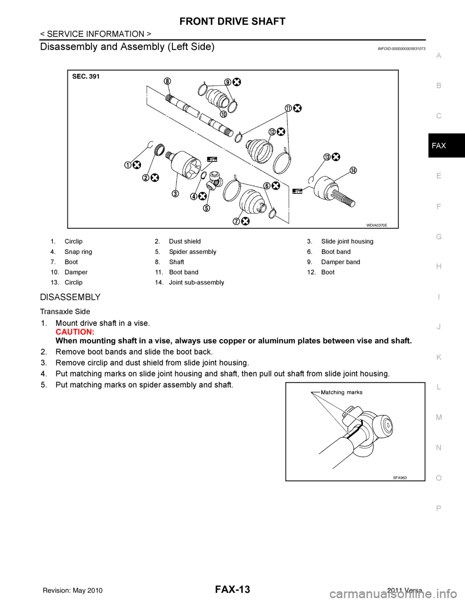
Disassembly and Assembly (Left Side)INFOID:0000000005931073
DISASSEMBLY
Transaxle Side
1. Mount drive shaft in a vise. CAUTION:
When mounting shaft in a vise, always use copper or alum inum plates between vise and shaft.
2. Remove boot bands and slide the boot back.
3. Remove circlip and dust shield from slide joint housing.
4. Put matching marks on slide joint housing and shaf t, then pull out shaft from slide joint housing.
5. Put matching marks on spider assembly and shaft.
1. Circlip 2. Dust shield 3. Slide joint housing
4. Snap ring 5. Spider assembly 6. Boot band
7. Boot 8. Shaft 9. Damper band
10. Damper 11. Boot band 12. Boot
13. Circlip 14. Joint sub-assembly
WDIA0370E
SFA963
Revision: May 2010 2011 Versa
Page 2656 of 3787
FAX-14
< SERVICE INFORMATION >
FRONT DRIVE SHAFT
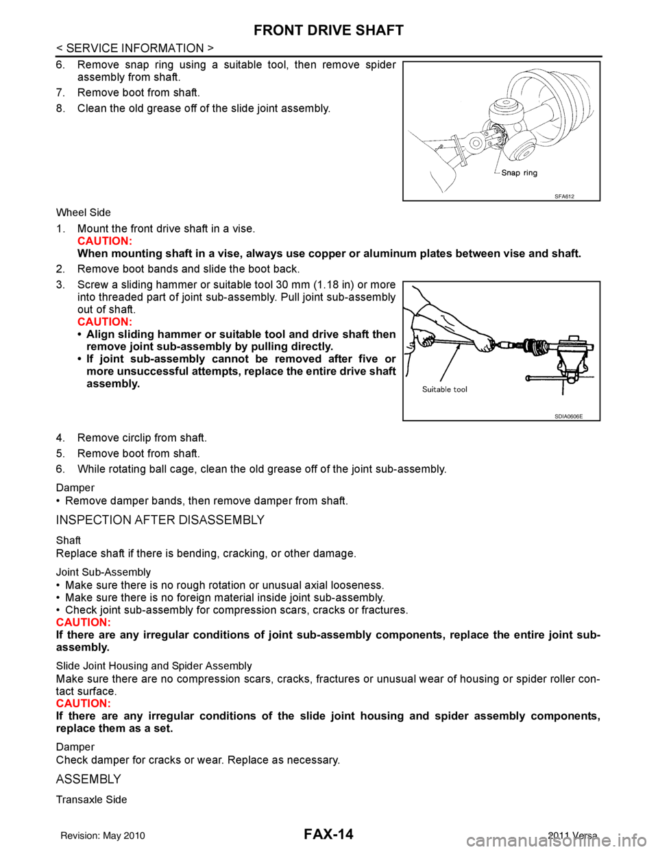
6. Remove snap ring using a suitable tool, then remove spiderassembly from shaft.
7. Remove boot from shaft.
8. Clean the old grease off of the slide joint assembly.
Wheel Side
1. Mount the front drive shaft in a vise. CAUTION:
When mounting shaf t in a vise, always use copper or al uminum plates between vise and shaft.
2. Remove boot bands and slide the boot back.
3. Screw a sliding hammer or suitable tool 30 mm (1.18 in) or more into threaded part of joint sub-assembly. Pull joint sub-assembly
out of shaft.
CAUTION:
• Align sliding hammer or suitab le tool and drive shaft then
remove joint sub-assembly by pulling directly.
• If joint sub-assembly cannot be removed after five or more unsuccessful attempts, replace the entire drive shaft
assembly.
4. Remove circlip from shaft.
5. Remove boot from shaft.
6. While rotating ball cage, clean the old grease off of the joint sub-assembly.
Damper
• Remove damper bands, then remove damper from shaft.
INSPECTION AFTER DISASSEMBLY
Shaft
Replace shaft if there is bending, cracking, or other damage.
Joint Sub-Assembly
• Make sure there is no rough rotation or unusual axial looseness.
• Make sure there is no foreign material inside joint sub-assembly.
• Check joint sub-assembly for compression scars, cracks or fractures.
CAUTION:
If there are any irregular condit ions of joint sub-assembly componen ts, replace the entire joint sub-
assembly.
Slide Joint Housing and Spider Assembly
Make sure there are no compression scars, cracks, fractures or unusual wear of housing or spider roller con-
tact surface.
CAUTION:
If there are any irregular conditions of the slide joint housing and spider assembly components,
replace them as a set.
Damper
Check damper for cracks or wear. Replace as necessary.
ASSEMBLY
Transaxle Side
SFA612
SDIA0606E
Revision: May 2010 2011 Versa
Page 2660 of 3787
FAX-18
< SERVICE INFORMATION >
FRONT DRIVE SHAFT
Damper
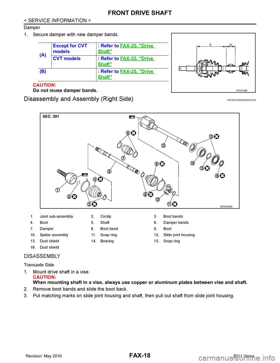
1. Secure damper with new damper bands.CAUTION:
Do not reuse damper bands.
Disassembly and Asse mbly (Right Side)INFOID:0000000005931074
DISASSEMBLY
Transaxle Side
1. Mount drive shaft in a vise.
CAUTION:
When mounting shaf t in a vise, always use copper or al uminum plates between vise and shaft.
2. Remove boot bands and slide the boot back.
3. Put matching marks on slide joint housing and shaf t, then pull out shaft from slide joint housing.
(A)
Except for CVT
models
: Refer to
FAX-25, "
Drive
Shaft"
CVT models : Refer to FAX-25, "Drive
Shaft"
(B): Refer to FAX-25, "Drive
Shaft"
FAC0156D
1. Joint sub-assembly 2. Circlip 3. Boot bands
4. Boot 5. Shaft 6. Damper bands
7. Damper 8. Boot band 9. Boot
10. Spider assembly 11. Snap ring 12. Slide joint housing
13. Dust shield 14. Bearing 15. Snap ring
16. Dust shield
WDIA0365E
Revision: May 2010 2011 Versa
Page 2662 of 3787

FAX-20
< SERVICE INFORMATION >
FRONT DRIVE SHAFT
2. Remove dust shield, then remove snap ring using a suitabletool.
3. Press support bearing assembly off slide joint assembly using a suitable tool.
4. Remove dust shield.
Damper
• Remove damper bands, then remove damper from shaft.
INSPECTION AFTER DISASSEMBLY
Shaft
Replace shaft if there is bending, cracking, or other damage.
Joint Sub-Assembly
• Make sure there is no rough rotation or unusual axial looseness.
• Make sure there is no foreign material inside joint sub-assembly.
• Check joint sub-assembly for compression scars, cracks or fractures.
CAUTION:
If there are any irregular condit ions of joint sub-assembly componen ts, replace the entire joint sub-
assembly.
Slide Joint Housing and Spider Assembly
Make sure there are no compression scars, cracks, fractures or unusual wear of housing or spider roller con-
tact surface.
CAUTION:
If there are any irregular conditions of the slide joint housing and spider assembly components,
replace them as a set.
Support Bearing
Make sure wheel bearing rolls freely and is free from noise, cracks, pitting or wear.
Support Bearing Bracket
Check for bending, cracks, or damage.
Damper
Check damper for cracks or wear. Replace as necessary.
ASSEMBLY
Transaxle Side
YAX003
YAX004
Revision: May 2010 2011 Versa