sensor oxygen NISSAN X-TRAIL 2001 Service Repair Manual
[x] Cancel search | Manufacturer: NISSAN, Model Year: 2001, Model line: X-TRAIL, Model: NISSAN X-TRAIL 2001Pages: 3833, PDF Size: 39.49 MB
Page 48 of 3833
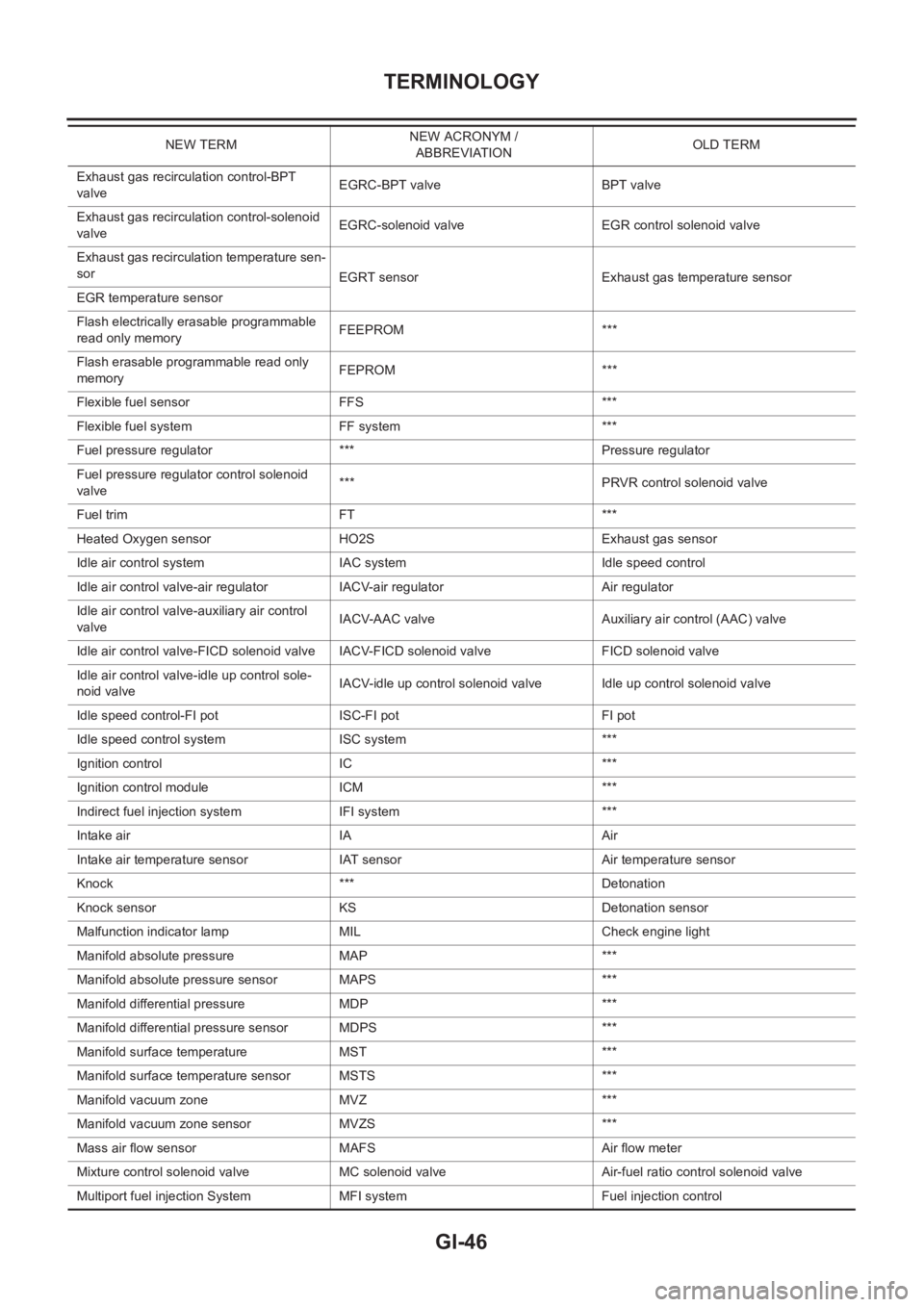
GI-46
TERMINOLOGY
Exhaust gas recirculation control-BPT
valveEGRC-BPT valve BPT valve
Exhaust gas recirculation control-solenoid
valveEGRC-solenoid valve EGR control solenoid valve
Exhaust gas recirculation temperature sen-
sor
EGRT sensor Exhaust gas temperature sensor
EGR temperature sensor
Flash electrically erasable programmable
read only memoryFEEPROM ***
Flash erasable programmable read only
memoryFEPROM ***
Flexible fuel sensor FFS ***
Flexible fuel system FF system ***
Fuel pressure regulator *** Pressure regulator
Fuel pressure regulator control solenoid
valve*** PRVR control solenoid valve
Fuel trim FT ***
Heated Oxygen sensor HO2S Exhaust gas sensor
Idle air control system IAC system Idle speed control
Idle air control valve-air regulator IACV-air regulator Air regulator
Idle air control valve-auxiliary air control
valveIACV-AAC valve Auxiliary air control (AAC) valve
Idle air control valve-FICD solenoid valve IACV-FICD solenoid valve FICD solenoid valve
Idle air control valve-idle up control sole-
noid valveIACV-idle up control solenoid valve Idle up control solenoid valve
Idle speed control-FI pot ISC-FI pot FI pot
Idle speed control system ISC system ***
Ignition control IC ***
Ignition control module ICM ***
Indirect fuel injection system IFI system ***
Intake air IA Air
Intake air temperature sensor IAT sensor Air temperature sensor
Knock *** Detonation
Knock sensor KS Detonation sensor
Malfunction indicator lamp MIL Check engine light
Manifold absolute pressure MAP ***
Manifold absolute pressure sensor MAPS ***
Manifold differential pressure MDP ***
Manifold differential pressure sensor MDPS ***
Manifold surface temperature MST ***
Manifold surface temperature sensor MSTS ***
Manifold vacuum zone MVZ ***
Manifold vacuum zone sensor MVZS ***
Mass air flow sensor MAFS Air flow meter
Mixture control solenoid valve MC solenoid valve Air-fuel ratio control solenoid valve
Multiport fuel injection System MFI system Fuel injection controlNEW TERMNEW ACRONYM /
ABBREVIATIONOLD TERM
Page 49 of 3833

TERMINOLOGY
GI-47
C
D
E
F
G
H
I
J
K
L
MB
GI
Nonvolatile random access memory NVRAM ***
On board diagnostic system OBD system Self-diagnosis
Open loop OL Open loop
Oxidation catalyst OC Catalyst
Oxidation catalytic converter system OC system ***
Oxygen sensor O2S Exhaust gas sensor
Park position switch *** Park switch
Park/neutral position switch PNP switchPark/neutral switch
Inhibitor switch
Neutral position switch
Periodic trap oxidizer system PTOX system ***
Positive crankcase ventilation PCV Positive crankcase ventilation
Positive crankcase ventilation valve PCV valve PCV valve
Powertrain control module PCM ***
Programmable read only memory PROM ***
Pulsed secondary air injection control sole-
noid valvePAIRC solenoid valve AIV control solenoid valve
Pulsed secondary air injection system PAIR system Air induction valve (AIV) control
Pulsed secondary air injection valve PAIR valve Air induction valve
Random access memory RAM ***
Read only memory ROM ***
Scan tool ST ***
Secondary air injection pump AIR pump ***
Secondary air injection system AIR system ***
Sequential multiport fuel injection system SFI system Sequential fuel injection
Service reminder indicator SRI ***
Simultaneous multiport fuel injection sys-
tem*** Simultaneous fuel injection
Smoke puff limiter system SPL system ***
Supercharger SC ***
Supercharger bypass SCB ***
System readiness test SRT ***
Thermal vacuum valve TVV Thermal vacuum valve
Three way catalyst TWC Catalyst
Three way catalytic converter system TWC system ***
Three way + oxidation catalyst TWC + OC Catalyst
Three way + oxidation catalytic converter
systemTWC + OC system ***
Throttle body TBThrottle chamber
SPI body
Throttle body fuel injection system TBI system Fuel injection control
Throttle position TP Throttle position
Throttle position sensor TPS Throttle sensor
Throttle position switch TP switch Throttle switch
Torque converter clutch solenoid valve TCC solenoid valveLock-up cancel solenoid
Lock-up solenoid NEW TERMNEW ACRONYM /
ABBREVIATIONOLD TERM
Page 57 of 3833
![NISSAN X-TRAIL 2001 Service Repair Manual PREPARATION
EM-7
[QR]
C
D
E
F
G
H
I
J
K
L
MA
EM
PREPARATIONPFP:00002
Special Service ToolsEBS00L7N
Tool number
To o l n a m eDescription
K V 1 0 1111 0 0
Seal cutterRemoving oil pan and timing chain NISSAN X-TRAIL 2001 Service Repair Manual PREPARATION
EM-7
[QR]
C
D
E
F
G
H
I
J
K
L
MA
EM
PREPARATIONPFP:00002
Special Service ToolsEBS00L7N
Tool number
To o l n a m eDescription
K V 1 0 1111 0 0
Seal cutterRemoving oil pan and timing chain](/img/5/57405/w960_57405-56.png)
PREPARATION
EM-7
[QR]
C
D
E
F
G
H
I
J
K
L
MA
EM
PREPARATIONPFP:00002
Special Service ToolsEBS00L7N
Tool number
To o l n a m eDescription
K V 1 0 1111 0 0
Seal cutterRemoving oil pan and timing chain case
ST0501S000
Engine stand assembly
1. ST05011000
Engine stand
2. ST05012000
BaseDisassembling and assembling
KV10106500
Engine stand shaft
KV10115300
Engine sub-attachment
KV10116200
Valve spring compressor
1. KV10115900
AttachmentDisassembling valve mechanism
KV10112100
Angle wrenchTightening bolts for bearing cap, cylinder
head, etc.
KV10117100
Heated oxygen sensor wrenchLoosening or tightening heated oxygen
sensors with 22 mm (0.87 in) hexagon nut
S-NT046
NT042
NT028
ZZA1078D
NT022
S-NT014
NT379
Page 74 of 3833
![NISSAN X-TRAIL 2001 Service Repair Manual EM-24
[QR]
EXHAUST MANIFOLD AND THREE WAY CATALYST
EXHAUST MANIFOLD AND THREE WAY CATALYST
PFP:14004
Removal and InstallationEBS00KND
REMOVAL
1. Remove heated oxygen sensors.
●Follow below steps to NISSAN X-TRAIL 2001 Service Repair Manual EM-24
[QR]
EXHAUST MANIFOLD AND THREE WAY CATALYST
EXHAUST MANIFOLD AND THREE WAY CATALYST
PFP:14004
Removal and InstallationEBS00KND
REMOVAL
1. Remove heated oxygen sensors.
●Follow below steps to](/img/5/57405/w960_57405-73.png)
EM-24
[QR]
EXHAUST MANIFOLD AND THREE WAY CATALYST
EXHAUST MANIFOLD AND THREE WAY CATALYST
PFP:14004
Removal and InstallationEBS00KND
REMOVAL
1. Remove heated oxygen sensors.
●Follow below steps to remove each heated oxygen sensor.
a. Remove engine undercover.
b. Disconnect harness connector of each heated oxygen sensor, and harness from bracket and middle
clamp.
c. Using heated oxygen sensor wrench, remove heated oxygen
sensors.
CAUTION:
●Be careful not to damage heated oxygen sensor.
●Discard any heated oxygen sensor which has been
dropped from a height of more than 0.5 m (19.7 in) onto a
hard surface such as a concrete floor; use a new one.
2. Remove exhaust manifold and three way catalyst assembly.
a. Remove exhaust manifold cover lower.
b. Remove exhaust front tube. Refer to EX-2, "
Removal and Instal-
lation" .
PBIC0279E
1.Exhaust manifold and three way cat-
alyst assembly2. Gasket 3. Exhaust manifold cover
4. Heated oxygen sensor 1 5. Heated oxygen sensor 2
KBIA0094E
Page 75 of 3833
![NISSAN X-TRAIL 2001 Service Repair Manual EXHAUST MANIFOLD AND THREE WAY CATALYST
EM-25
[QR]
C
D
E
F
G
H
I
J
K
L
MA
EM
c. Remove exhaust manifold cover upper.
d. Loosen nuts in reverse order of illustration to remove exhaust
manifold NISSAN X-TRAIL 2001 Service Repair Manual EXHAUST MANIFOLD AND THREE WAY CATALYST
EM-25
[QR]
C
D
E
F
G
H
I
J
K
L
MA
EM
c. Remove exhaust manifold cover upper.
d. Loosen nuts in reverse order of illustration to remove exhaust
manifold](/img/5/57405/w960_57405-74.png)
EXHAUST MANIFOLD AND THREE WAY CATALYST
EM-25
[QR]
C
D
E
F
G
H
I
J
K
L
MA
EM
c. Remove exhaust manifold cover upper.
d. Loosen nuts in reverse order of illustration to remove exhaust
manifold and catalytic converter.
●Disregard the numerical order No. 6 and 7 when loosening.
3. Remove exhaust manifold and three way catalyst loosening nuts
in reverse order in the figure.
INSPECTION AFTER REMOVAL
Surface Distortion
Use a reliable straightedge and feeler gauge to check the flatness of
exhaust manifold fitting surface.
INSTALLATION
Install in the reverse order of removal paying attention to the following.
Exhaust Manifold Nuts
●Tighten nuts in the numerical order shown in the figure.
●No. 6 and 7 indicate double tightening of bolts No. 1 and 3.
Heated Oxygen Sensor
CAUTION:
Do not over torque the heated oxygen sensor. Doing so may cause damage to the heated oxygen sen-
sor, resulting in the MIL coming on.
KBIA0045E
Standard: 0.3 mm (0.012 in)
KBIA0046E
KBIA0045E
Page 158 of 3833
![NISSAN X-TRAIL 2001 Service Repair Manual EM-108
[QR]
SERVICE DATA AND SPECIFICATIONS (SDS)
Bearing Oil Clearance
Unit: mm (in)
Tightening TorqueEBS00KNY
Unit: N·m (kg-m, ft-lb)
Unit: N·m (kg-m, in-lb)*2
Connecting rod bearing oil clearance NISSAN X-TRAIL 2001 Service Repair Manual EM-108
[QR]
SERVICE DATA AND SPECIFICATIONS (SDS)
Bearing Oil Clearance
Unit: mm (in)
Tightening TorqueEBS00KNY
Unit: N·m (kg-m, ft-lb)
Unit: N·m (kg-m, in-lb)*2
Connecting rod bearing oil clearance](/img/5/57405/w960_57405-157.png)
EM-108
[QR]
SERVICE DATA AND SPECIFICATIONS (SDS)
Bearing Oil Clearance
Unit: mm (in)
Tightening TorqueEBS00KNY
Unit: N·m (kg-m, ft-lb)
Unit: N·m (kg-m, in-lb)*2
Connecting rod bearing oil clearanceStandard 0.028 - 0.045 (0.0011 - 0.0018)
Limit 0.10 (0.0039)
*1: Parts to be tightened in particular orders.
1)-: Order of tightening when tightening two or more times separately.
Auto-tensioner 19.6 - 23.5 (2.0 - 2.4, 15 - 17)
Mass air flow sensor
3.8 - 4.5 (0.39 - 0.46, 34 - 39) *
2
Resonator
3.8 - 4.5 (0.39 - 0.46, 34 - 39)*2
Air cleaner case lower
3.8 - 4.5 (0.39 - 0.46, 34 - 39)*2
*1 Intake manifold17.6 - 21.6 (1.8 - 2.2, 13 - 15)
Intake manifold collector 17.6 - 21.6 (1.8 - 2.2, 13 - 15)
Intake manifold support 17.6 - 21.6 (1.8 - 2.2, 13 - 15)
Electric throttle control actuator
7.2 - 9.6 (0.74 - 0.98, 64 - 84) *
2
EVAP canister purge volume control solenoid valve
4.3 - 5.8 (0.44 - 0.59, 38 - 51) *2
*1 Exhaust manifold 39.2 - 44.1 (4.0 - 4.5, 29 - 32)
Exhaust manifold cover
5.1 - 6.5 (0.52 - 0.66, 46 - 57) *
2
Heated oxygen sensor 40 - 50 (4.1 - 5.1, 30 - 36)
*1 Oil pan upper M6 bolt
8.1 - 9.5 (0.83 - 0.97, 72 - 84) *
2
M8 bolt 19.6 - 23.5 (2.0 - 2.4, 15 - 17)
Oil pan upper to transmission joint bolts 39.2 - 46.1 (4.0 - 4.7, 29 - 34)
*1 Oil pan lower
6.4 - 7.5 (0.65 - 0.76, 57 - 66) *
2
Oil pan drain plug29.4 - 39.2 (3.0 - 4.0, 22 - 28)
Rear plate cover
6.4 - 7.5 (0.65 - 0.76, 57 - 66) *
2
Oil strainer M6 bolt
8.1 - 9.5 (0.83 - 0.97, 72 - 84) *2
M8 bolt 19.6 - 23.5 (2.0 - 2.4, 15 - 17)
Oil level gauge guide 19.6 - 23.5 (2.0 - 2.4, 15 - 17)
Ignition coil
5.4 - 7.3 (0.55 - 0.75, 48 - 64) *
2
Spark plug19.6 - 29.4 (2.0 - 3.0, 15 - 21)
*1 Fuel tube1)
2)9.3 - 10.8 (0.95 - 1.1, 0.7 - 0.8) *
2
20.6 - 26.5 (2.1 - 2.7, 16 - 19)
*1 Rocker cover1)
2)0.98 - 2.9 (0.1 - 0.3, 9 - 25) *
2
7.4 - 9.3 (0.75 - 0.95, 66 - 82) *2
PCV valve
1.96 - 2.94 (0.20 - 0.30, 18 - 26) *2
Intake valve timing control solenoid valve
5.4 - 7.3 (0.55 - 0.75, 48 - 64) *2
*1 Intake valve timing control cover 11.8 - 13.7 (1.2 - 1.4, 9 - 10)
Camshaft position sensor (PHASE)
5.4 - 7.3 (0.55 - 0.75, 48 - 64) *
2
Camshaft sprocket (Intake and Exhaust) 127- 157 (13.0 - 16.0, 94 - 115)
Chain tensioner
6.4 - 7.5 (0.65 - 0.76, 57 - 66) *
2
Page 356 of 3833
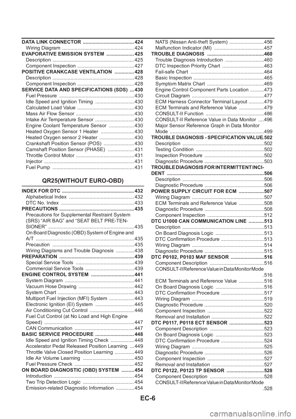
EC-6
DATA LINK CONNECTOR ......................................424
Wiring Diagram .....................................................424
EVAPORATIVE EMISSION SYSTEM .....................425
Description ............................................................425
Component Inspection ..........................................427
POSITIVE CRANKCASE VENTILATION ...............428
Description ............................................................428
Component Inspection ..........................................428
SERVICE DATA AND SPECIFICATIONS (SDS) ....430
Fuel Pressure .......................................................430
Idle Speed and Ignition Timing .............................430
Calculated Load Value ..........................................430
Mass Air Flow Sensor ...........................................430
Intake Air Temperature Sensor .............................430
Engine Coolant Temperature Sensor ...................430
Heated Oxygen Sensor 1 Heater .........................430
Heated Oxygen sensor 2 Heater ..........................430
Crankshaft Position Sensor (POS) .......................430
Camshaft Position Sensor (PHASE) ....................431
Throttle Control Motor ...........................................431
Injector ..................................................................431
Fuel Pump ............................................................431
QR25(WITHOUT EURO-OBD)
INDEX FOR DTC .....................................................432
Alphabetical Index ................................................432
DTC No. Index ......................................................433
PRECAUTIONS .......................................................435
Precautions for Supplemental Restraint System
(SRS) “AIR BAG” and “SEAT BELT PRE-TEN-
SIONER” ...............................................................435
On Board Diagnostic (OBD) System of Engine and
A/T ........................................................................435
Precaution ............................................................435
Wiring Diagrams and Trouble Diagnosis ..............438
PREPARATION .......................................................439
Special Service Tools ...........................................439
Commercial Service Tools ....................................439
ENGINE CONTROL SYSTEM ................................441
System Diagram ...................................................441
Vacuum Hose Drawing .........................................442
System Chart ........................................................443
Multiport Fuel Injection (MFI) System ...................443
Electronic Ignition (EI) System .............................445
Air Conditioning Cut Control .................................446
Fuel Cut Control (at No Load and High Engine
Speed) ..................................................................447
CAN Communication ............................................447
BASIC SERVICE PROCEDURE .............................448
Idle Speed and Ignition Timing Check ..................448
Accelerator Pedal Released Position Learning ....449
Throttle Valve Closed Position Learning ...............449
Idle Air Volume Learning ......................................450
Fuel Pressure Check ............................................452
ON BOARD DIAGNOSTIC (OBD) SYSTEM ..........454
Introduction ...........................................................454
Two Trip Detection Logic ......................................454
Emission-related Diagnostic Information ..............454NATS (Nissan Anti-theft System) ..........................456
Malfunction Indicator (MI) .....................................457
TROUBLE DIAGNOSIS ..........................................460
Trouble Diagnosis Introduction .............................460
DTC Inspection Priority Chart ...............................463
Fail-safe Chart ......................................................464
Basic Inspection ....................................................465
Symptom Matrix Chart ..........................................469
Engine Control Component Parts Location ...........473
Circuit Diagram .....................................................477
ECM Harness Connector Terminal Layout ............479
ECM Terminals and Reference Value ...................479
CONSULT-II Function ...........................................486
CONSULT-II Reference Value in Data Monitor .....496
Major Sensor Reference Graph in Data Monitor
Mode .....................................................................499
TROUBLE DIAGNOSIS - SPECIFICATION VALUE .502
Description ............................................................502
Testing Condition ..................................................502
Inspection Procedure ........................................... .502
Diagnostic Procedure ............................................503
TROUBLE DIAGNOSIS FOR INTERMITTENT INCI-
DENT .......................................................................506
Description ............................................................506
Diagnostic Procedure ............................................506
POWER SUPPLY CIRCUIT FOR ECM ...................507
Wiring Diagram .....................................................507
ECM Terminals and Reference Value ...................508
Diagnostic Procedure ............................................508
Component Inspection ..........................................512
DTC U1000 CAN COMMUNICATION LINE ............513
Description ............................................................513
On Board Diagnosis Logic ....................................513
DTC Confirmation Procedure ................................513
Wiring Diagram .....................................................514
Diagnostic Procedure ............................................515
DTC P0102, P0103 MAF SENSOR .........................516
Component Description ........................................516
CONSULT-II Reference Value in Data Monitor Mode
.516
ECM Terminals and Reference Value ...................516
On Board Diagnosis Logic ....................................516
DTC Confirmation Procedure ................................517
Wiring Diagram .....................................................519
Diagnostic Procedure ............................................520
Component Inspection ..........................................522
Removal and Installation .......................................522
DTC P0117, P0118 ECT SENSOR ..........................523
Component Description ........................................523
On Board Diagnosis Logic ....................................523
DTC Confirmation Procedure ................................524
Wiring Diagram .....................................................525
Diagnostic Procedure ............................................526
Component Inspection ..........................................527
Removal and Installation .......................................527
DTC P0122, P0123 TP SENSOR ............................528
Component Description ........................................528
CONSULT-II Reference Value in Data Monitor Mode
.528
Page 359 of 3833
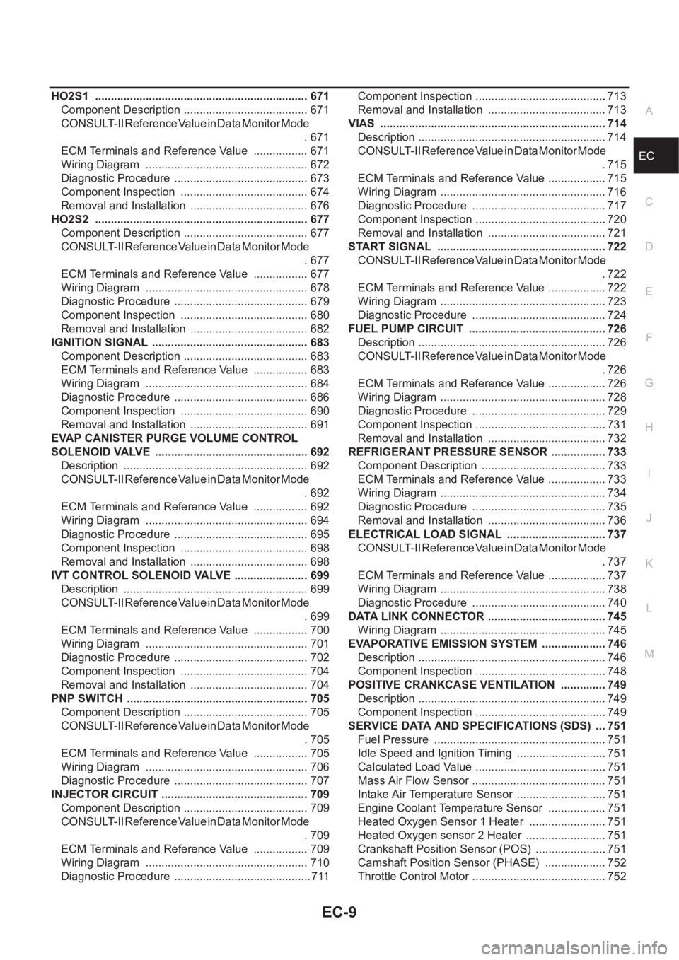
EC-9
C
D
E
F
G
H
I
J
K
L
M
ECA HO2S1 .................................................................... 671
Component Description ........................................ 671
CONSULT-II Reference Value in Data Monitor Mode
. 671
ECM Terminals and Reference Value .................. 671
Wiring Diagram .................................................... 672
Diagnostic Procedure ........................................... 673
Component Inspection ......................................... 674
Removal and Installation ...................................... 676
HO2S2 .................................................................... 677
Component Description ........................................ 677
CONSULT-II Reference Value in Data Monitor Mode
. 677
ECM Terminals and Reference Value .................. 677
Wiring Diagram .................................................... 678
Diagnostic Procedure ........................................... 679
Component Inspection ......................................... 680
Removal and Installation ...................................... 682
IGNITION SIGNAL .................................................. 683
Component Description ........................................ 683
ECM Terminals and Reference Value .................. 683
Wiring Diagram .................................................... 684
Diagnostic Procedure ........................................... 686
Component Inspection ......................................... 690
Removal and Installation ...................................... 691
EVAP CANISTER PURGE VOLUME CONTROL
SOLENOID VALVE ................................................. 692
Description ........................................................... 692
CONSULT-II Reference Value in Data Monitor Mode
. 692
ECM Terminals and Reference Value .................. 692
Wiring Diagram .................................................... 694
Diagnostic Procedure ........................................... 695
Component Inspection ......................................... 698
Removal and Installation ...................................... 698
IVT CONTROL SOLENOID VALVE ........................ 699
Description ........................................................... 699
CONSULT-II Reference Value in Data Monitor Mode
. 699
ECM Terminals and Reference Value .................. 700
Wiring Diagram .................................................... 701
Diagnostic Procedure ........................................... 702
Component Inspection ......................................... 704
Removal and Installation ...................................... 704
PNP SWITCH .......................................................... 705
Component Description ........................................ 705
CONSULT-II Reference Value in Data Monitor Mode
. 705
ECM Terminals and Reference Value .................. 705
Wiring Diagram ...................................................
. 706
Diagnostic Procedure ........................................... 707
INJECTOR CIRCUIT ............................................... 709
Component Description ........................................ 709
CONSULT-II Reference Value in Data Monitor Mode
. 709
ECM Terminals and Reference Value .................. 709
Wiring Diagram .................................................... 710
Diagnostic Procedure ............................................ 711Component Inspection ..........................................713
Removal and Installation ......................................713
VIAS ........................................................................714
Description ............................................................714
CONSULT-II Reference Value in Data Monitor Mode
.715
ECM Terminals and Reference Value ...................715
Wiring Diagram .....................................................716
Diagnostic Procedure ...........................................717
Component Inspection ..........................................720
Removal and Installation ......................................721
START SIGNAL ......................................................722
CONSULT-II Reference Value in Data Monitor Mode
.722
ECM Terminals and Reference Value ...................722
Wiring Diagram .....................................................723
Diagnostic Procedure ...........................................724
FUEL PUMP CIRCUIT ............................................726
Description ............................................................726
CONSULT-II Reference Value in Data Monitor Mode
.726
ECM Terminals and Reference Value ...................726
Wiring Diagram .....................................................728
Diagnostic Procedure ...........................................729
Component Inspection ..........................................731
Removal and Installation ......................................732
REFRIGERANT PRESSURE SENSOR ..................733
Component Description ........................................733
ECM Terminals and Reference Value ...................733
Wiring Diagram .....................................................734
Diagnostic Procedure ...........................................735
Removal and Installation ......................................736
ELECTRICAL LOAD SIGNAL ................................737
CONSULT-II Reference Value in Data Monitor Mode
.737
ECM Terminals and Reference Value ...................737
Wiring Diagram .....................................................738
Diagnostic Procedure ...........................................740
DATA LINK CONNECTOR ......................................745
Wiring Diagram .....................................................745
EVAPORATIVE EMISSION SYSTEM .....................746
Description ...................................................
.........746
Component Inspection ..........................................748
POSITIVE CRANKCASE VENTILATION ...............749
Description ............................................................749
Component Inspection ..........................................749
SERVICE DATA AND SPECIFICATIONS (SDS) ....751
Fuel Pressure .......................................................751
Idle Speed and Ignition Timing .............................751
Calculated Load Value ..........................................751
Mass Air Flow Sensor ...........................................751
Intake Air Temperature Sensor .............................751
Engine Coolant Temperature Sensor ...................751
Heated Oxygen Sensor 1 Heater .........................751
Heated Oxygen sensor 2 Heater ..........................751
Crankshaft Position Sensor (POS) .......................751
Camshaft Position Sensor (PHASE) ....................752
Throttle Control Motor ...........................................752
Page 364 of 3833
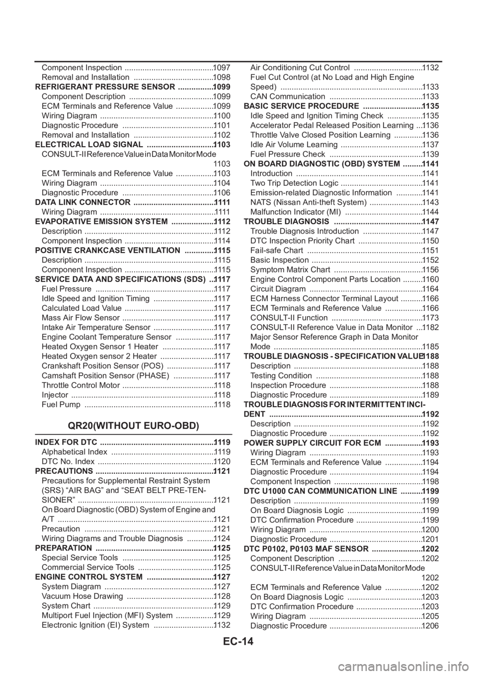
EC-14
Component Inspection .........................................1097
Removal and Installation .....................................1098
REFRIGERANT PRESSURE SENSOR .................1099
Component Description .......................................1099
ECM Terminals and Reference Value ..................1099
Wiring Diagram ....................................................11 0 0
Diagnostic Procedure ..........................................11 0 1
Removal and Installation .....................................11 0 2
ELECTRICAL LOAD SIGNAL ...............................110 3
CONSULT-II Reference Value in Data Monitor Mode
11 0 3
ECM Terminals and Reference Value ..................11 0 3
Wiring Diagram ....................................................11 0 4
Diagnostic Procedure ..........................................11 0 6
DATA LINK CONNECTOR .....................................1111
Wiring Diagram ....................................................1111
EVAPORATIVE EMISSION SYSTEM ....................111 2
Description ...........................................................111 2
Component Inspection .........................................111 4
POSITIVE CRANKCASE VENTILATION ..............111 5
Description ...........................................................111 5
Component Inspection .........................................111 5
SERVICE DATA AND SPECIFICATIONS (SDS) ...111 7
Fuel Pressure ......................................................111 7
Idle Speed and Ignition Timing ............................111 7
Calculated Load Value .........................................111 7
Mass Air Flow Sensor ..........................................111 7
Intake Air Temperature Sensor ............................111 7
Engine Coolant Temperature Sensor ..................111 7
Heated Oxygen Sensor 1 Heater ........................111 7
Heated Oxygen sensor 2 Heater .........................111 7
Crankshaft Position Sensor (POS) ......................111 7
Camshaft Position Sensor (PHASE) ...................111 7
Throttle Control Motor ..........................................111 8
Injector .................................................................111 8
Fuel Pump ...........................................................111 8
QR20(WITHOUT EURO-OBD)
INDEX FOR DTC ....................................................111 9
Alphabetical Index ...............................................111 9
DTC No. Index .....................................................11 2 0
PRECAUTIONS ......................................................112 1
Precautions for Supplemental Restraint System
(SRS) “AIR BAG” and “SEAT BELT PRE-TEN-
SIONER” ..............................................................11 2 1
On Board Diagnostic (OBD) System of Engine and
A/T .......................................................................11 2 1
Precaution ...........................................................11 2 1
Wiring Diagrams and Trouble Diagnosis .............11 2 4
PREPARATION ......................................................112 5
Special Service Tools .......................................... 11 2 5
Commercial Service Tools ...................................11 2 5
ENGINE CONTROL SYSTEM ...............................112 7
System Diagram ..................................................11 2 7
Vacuum Hose Drawing ........................................11 2 8
System Chart .......................................................11 2 9
Multiport Fuel Injection (MFI) System ..................11 2 9
Electronic Ignition (EI) System ............................11 3 2Air Conditioning Cut Control ................................11 3 2
Fuel Cut Control (at No Load and High Engine
Speed) .................................................................11 3 3
CAN Communication ...........................................11 3 3
BASIC SERVICE PROCEDURE ............................11 35
Idle Speed and Ignition Timing Check .................11 3 5
Accelerator Pedal Released Position Learning ....11 3 6
Throttle Valve Closed Position Learning ..............11 3 6
Idle Air Volume Learning ......................................11 3 7
Fuel Pressure Check ...........................................11 3 9
ON BOARD DIAGNOSTIC (OBD) SYSTEM ..........11 41
Introduction ..........................................................11 4 1
Two Trip Detection Logic ......................................11 4 1
Emission-related Diagnostic Information .............11 4 1
NATS (Nissan Anti-theft System) .........................11 4 3
Malfunction Indicator (MI) ....................................11 4 4
TROUBLE DIAGNOSIS .........................................11 47
Trouble Diagnosis Introduction ............................11 4 7
DTC Inspection Priority Chart ..............................11 5 0
Fail-safe Chart .....................................................11 5 1
Basic Inspection ...................................................11 5 2
Symptom Matrix Chart .........................................11 5 6
Engine Control Component Parts Location ..........11 6 0
Circuit Diagram ....................................................11 6 4
ECM Harness Connector Terminal Layout ...........11 6 6
ECM Terminals and Reference Value ..................11 6 6
CONSULT-II Function ..........................................
11 7 3
CONSULT-II Reference Value in Data Monitor ....11 8 2
Major Sensor Reference Graph in Data Monitor
Mode ....................................................................11 8 5
TROUBLE DIAGNOSIS - SPECIFICATION VALUE 11 88
Description ...........................................................11 8 8
Testing Condition .................................................11 8 8
Inspection Procedure ........................................... 11 8 8
Diagnostic Procedure ........................................... 11 8 9
TROUBLE DIAGNOSIS FOR INTERMITTENT INCI-
DENT ......................................................................11 92
Description ...........................................................11 9 2
Diagnostic Procedure ........................................... 11 9 2
POWER SUPPLY CIRCUIT FOR ECM ..................11 93
Wiring Diagram ....................................................11 9 3
ECM Terminals and Reference Value ..................11 9 4
Diagnostic Procedure ........................................... 11 9 4
Component Inspection .........................................11 9 8
DTC U1000 CAN COMMUNICATION LINE ...........11 99
Description ...........................................................11 9 9
On Board Diagnosis Logic ...................................11 9 9
DTC Confirmation Procedure ...............................11 9 9
Wiring Diagram ....................................................1200
Diagnostic Procedure ........................................... 1201
DTC P0102, P0103 MAF SENSOR ........................1202
Component Description .......................................1202
CONSULT-II Reference Value in Data Monitor Mode
1202
ECM Terminals and Reference Value ..................1202
On Board Diagnosis Logic ...................................1203
DTC Confirmation Procedure ...............................1203
Wiring Diagram ....................................................1205
Diagnostic Procedure ........................................... 1206
Page 367 of 3833
EC-17
C
D
E
F
G
H
I
J
K
L
M
ECA INJECTOR CIRCUIT ..............................................1357
Component Description .......................................1357
CONSULT-II Reference Value in Data Monitor Mode
1357
ECM Terminals and Reference Value .................1357
Wiring Diagram ...................................................1358
Diagnostic Procedure ..........................................1359
Component Inspection ........................................1361
Removal and Installation .....................................1361
START SIGNAL .....................................................1362
CONSULT-II Reference Value in Data Monitor Mode
1362
ECM Terminals and Reference Value .................1362
Wiring Diagram ...................................................1363
Diagnostic Procedure ..........................................1364
FUEL PUMP CIRCUIT ...........................................1366
Description ..........................................................1366
CONSULT-II Reference Value in Data Monitor Mode
1366
ECM Terminals and Reference Value .................1366
Wiring Diagram ...................................................1368
Diagnostic Procedure ..........................................1369
Component Inspection ........................................1371
Removal and Installation .....................................1372
REFRIGERANT PRESSURE SENSOR ................1373
Component Description .......................................1373
ECM Terminals and Reference Value .................1373
Wiring Diagram ...................................................1374
Diagnostic Procedure ..........................................1375
Removal and Installation .....................................1376
ELECTRICAL LOAD SIGNAL ...............................1377
CONSULT-II Reference Value in Data Monitor Mode
1377
ECM Terminals and Reference Value .................1377
Wiring Diagram ...................................................1378
Diagnostic Procedure ..........................................1380
DATA LINK CONNECTOR ....................................1385
Wiring Diagram ...................................................1385
EVAPORATIVE EMISSION SYSTEM ....................1386
Description ..........................................................1386
Component Inspection ........................................1388
POSITIVE CRANKCASE VENTILATION ..............1389
Description ..........................................................1389
Component Inspection ........................................1389
SERVICE DATA AND SPECIFICATIONS (SDS) ...1391
Fuel Pressure ......................................................1391
Idle Speed and Ignition Timing ............................1391
Calculated Load Value ........................................1391
Mass Air Flow Sensor .........................................1391
Intake Air Temperature Sensor ...........................1391
Engine Coolant Temperature Sensor ..................1391
Heated Oxygen Sensor 1 Heater ........................1391
Heated Oxygen sensor 2 Heater .........................1391
Crankshaft Position Sensor (POS) ......................1391
Camshaft Position Sensor (PHASE) ...................1391
Throttle Control Motor ......................................... 1392
Injector ................................................................1392
Fuel Pump ...........................................................1392
YD
INDEX FOR DTC ....................................................1393
Alphabetical Index ...............................................1393
DTC No. Index .....................................................1393
PRECAUTIONS .....................................................1395
Precautions for Supplemental Restraint System
(SRS) “AIR BAG” and “SEAT BELT PRE-TEN-
SIONER” ..............................................................1395
Precautions ..........................................................1395
Wiring Diagrams and Trouble Diagnosis .............1397
ENGINE CONTROL SYSTEM ...............................1398
System Diagram ..................................................1398
System Chart .......................................................1399
Fuel Injection Control System ..............................1399
Fuel Injection Timing Control System ..................1401
Air Conditioning Cut Control ................................1401
F u e l C u t C o n t r o l ( A t N o L o a d & H i g h E n g i n e S p e e d ) 1401
Crankcase Ventilation System .............................1402
CAN Communication ...........................................1402
BASIC SERVICE PROCEDURE ............................1404
Fuel Filter .............................................................1404
Accelerator Pedal Released Position Learning ...1404
Fuel Pressure Relief Valve ..................................1405
ON BOARD DIAGNOSTIC (OBD) SYSTEM .........1406
DTC and MI Detection Logic ...............................1406
Diagnostic Trouble Code (DTC) ..........................1406
NATS (Nissan Anti-theft System) ........................1406
Malfunction Indicator (MI) ....................................1407
TROUBLE DIAGNOSIS .........................................1409
Trouble Diagnosis Introduction ............................1409
Basic Inspection ..................................................1412
Symptom Matrix Chart .........................................1416
Engine Control Component Parts Location .........1420
Circuit Diagram ....................................................1423
ECM Harness Connector Terminal Layout ..........1425
ECM Terminals And Reference Value .................1425
CONSULT-II Function ..........................................1431
CONSULT-II Reference Value in Data Monitor Mode
1437
Major Sensor Reference Graph in Data Monitor
Mode ....................................................................1440
TROUBLE DIAGNOSIS FOR INTERMITTENT INCI-
DENT ......................................................................1441
Description ...........................................................1441
Diagnostic Procedure ..........................................1441
POWER SUPPLY CIRCUIT FOR ECM ..................1442
ECM Terminals and Reference Value ..................1442
Wiring Diagram ....................................................1443
Diagnostic Procedure ..........................................1444
Component Inspection .........................................1447
DTC U1000 CAN COMMUNICATION LINE ...........1448
Description ...........................................................1448
On Board Diagnosis Logic ...................................1448
DTC Confirmation Procedure ..............................1448
Wiring Diagram ....................................................1449
Diagnostic Procedure ..........................................1450
DTC P0100 MASS AIR FLOW SENSOR (MAFS) .1451
Component Description .......................................1451