Shaft NISSAN X-TRAIL 2001 Service Repair Manual
[x] Cancel search | Manufacturer: NISSAN, Model Year: 2001, Model line: X-TRAIL, Model: NISSAN X-TRAIL 2001Pages: 3833, PDF Size: 39.49 MB
Page 298 of 3833

LU-18
[YD22DDTi]
ENGINE OIL
ENGINE OIL
PFP:KLA92
InspectionEBS00B03
ENGINE OIL LEVEL AND MUDDINESS
●Before starting the engine, put vehicle horizontally then check
the engine oil level. If the engine is already started, stop it and
allow 10 minutes before checking.
●Check that the engine oil level is within the range shown in the
figure.
●If it is out of range, adjust it.
●Check the engine oil for white turbidity or remarkable contamina-
tion.
●If the engine oil becomes turbid and white, it is highly probable
that it is contaminated with engine coolant. Find the cause and
repair.
ENGINE OIL LEAKAGE
Check for engine oil leakage around the following area.
●Oil pan
●Oil pan drain plug
●Oil pressure switch
●Oil filter bracket
●Oil cooler.
●Oil pump housing
●Vacuum pump
●Cylinder head rear cover assembly
●Chain case
●Mating surface between cylinder block and cylinder head
●Mating surface between cylinder head and rocker cover
●Crankshaft oil seal. Refer to LU-18, "ENGINE OIL LEVEL AND MUDDINESS" .
ENGINE OIL PRESSURE CHECK
WARNING:
●Be careful not to burn yourself, as the engine oil is hot.
●Oil pressure check should be done in “ Neutral position”.
1. Check the engine oil level. Refer to LU-18, "
ENGINE OIL LEVEL
AND MUDDINESS" .
2. Remove the undercover.
3. Remove the oil pressure switch to connect the oil pressure
gauge.
4. After warming up the engine, check that oil pressure corre-
sponding to the engine speed is produced.
Engine oil pressure [Engine oil temperature at 80 °C (176 °F)]
5. After checking, install the oil pressure switch as follows.
a. Remove old sealant adhering to the switch and engine.
b. Apply thread sealant.
Use Genuine Liquid Gasket or equivalent.
SBIA0122E
SBIA0123E
Engine speed (rpm) Idle speed 2,000 4,000
Engine pressure
kPa (bar, kg/cm
2 , psi)Approx. 140 (1.40, 1.43, 20.3) or
moreApprox. 270 (2.69, 2.75, 39.1) or
moreApprox. 430 (4.29, 4.38, 62.3) or
more
Page 325 of 3833

WATER PUMP
CO-19
[QR]
C
D
E
F
G
H
I
J
K
L
MA
CO
3. Remove water pipe.
INSPECTION AFTER REMOVAL
●Visually check that there is no significant dirt or rusting on the
water pump body and vane.
●Check that there is no looseness in the vane shaft, and that it
turns smoothly when rotated by hand.
●If there are any unusualness, replace the water pump assembly.
INSTALLATION
●Install in the reverse order of removal
●When inserting water pipe end to cylinder block, apply a neutral detergent to o-ring. Then insert it immedi-
ately.
INSPECTION AFTER INSTALLATION
Check for engine coolant leaks using radiator cap tester. Refer to CO-9, "CHECKING RADIATOR SYSTEM
FOR LEAKS" .
KBIA0155E
Page 345 of 3833

WATER PUMP
CO-39
[YD22DDTi]
C
D
E
F
G
H
I
J
K
L
MA
CO
WAT E R P U MPPFP:21020
Removal and InstallationEBS00BB4
WARNING:
Never remove the radiator cap when the engine is hot. Serious burns could occur from high pressure
engine coolant escaping from the radiator.
REMOVAL
1. Remove the under cover, splash cover (right), and drive belt.
2. Drain engine coolant. Refer to CO-29, "
DRAINING ENGINE COOLANT" .
CAUTION:
Perform when the engine is cold.
3. Support the bottom of the oil pan with a floor jack etc, and remove the right engine mount bracket (front
side of the engine).
4. Remove the water pump pulley.
●Loosen the pulley bolts after fixing the pulley using a screwdriver etc.
5. Remove engine mount bracket.
6. Remove the water pump.
●Engine coolant will leak from the cylinder block, so have a receptacle ready below.
CAUTION:
●Handle the water pump vane so that it does not contact any other parts.
●Water pump cannot be disassembled and should be replaced as a unit.
INSPECTION AFTER REMOVAL
●Visually check that there is no significant dirt or rusting on the
water pump body and vane.
●Check that there is no looseness in the vane shaft, and that it
turns smoothly when rotated by hand.
●If there are any unusualness, replace the water pump assembly.
JLC294B
SBIA0132E
Page 356 of 3833
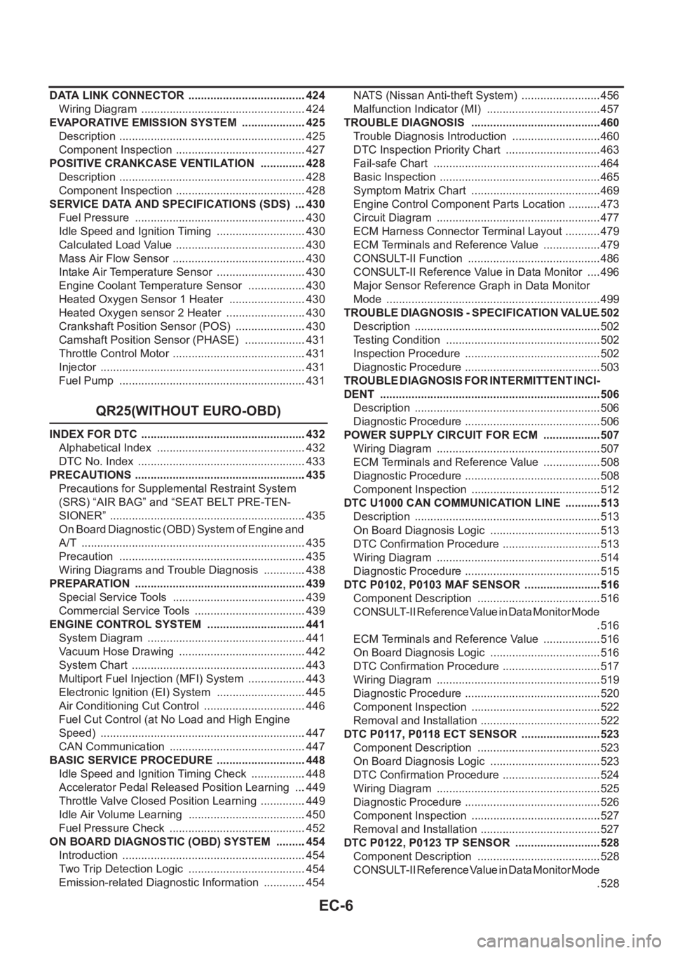
EC-6
DATA LINK CONNECTOR ......................................424
Wiring Diagram .....................................................424
EVAPORATIVE EMISSION SYSTEM .....................425
Description ............................................................425
Component Inspection ..........................................427
POSITIVE CRANKCASE VENTILATION ...............428
Description ............................................................428
Component Inspection ..........................................428
SERVICE DATA AND SPECIFICATIONS (SDS) ....430
Fuel Pressure .......................................................430
Idle Speed and Ignition Timing .............................430
Calculated Load Value ..........................................430
Mass Air Flow Sensor ...........................................430
Intake Air Temperature Sensor .............................430
Engine Coolant Temperature Sensor ...................430
Heated Oxygen Sensor 1 Heater .........................430
Heated Oxygen sensor 2 Heater ..........................430
Crankshaft Position Sensor (POS) .......................430
Camshaft Position Sensor (PHASE) ....................431
Throttle Control Motor ...........................................431
Injector ..................................................................431
Fuel Pump ............................................................431
QR25(WITHOUT EURO-OBD)
INDEX FOR DTC .....................................................432
Alphabetical Index ................................................432
DTC No. Index ......................................................433
PRECAUTIONS .......................................................435
Precautions for Supplemental Restraint System
(SRS) “AIR BAG” and “SEAT BELT PRE-TEN-
SIONER” ...............................................................435
On Board Diagnostic (OBD) System of Engine and
A/T ........................................................................435
Precaution ............................................................435
Wiring Diagrams and Trouble Diagnosis ..............438
PREPARATION .......................................................439
Special Service Tools ...........................................439
Commercial Service Tools ....................................439
ENGINE CONTROL SYSTEM ................................441
System Diagram ...................................................441
Vacuum Hose Drawing .........................................442
System Chart ........................................................443
Multiport Fuel Injection (MFI) System ...................443
Electronic Ignition (EI) System .............................445
Air Conditioning Cut Control .................................446
Fuel Cut Control (at No Load and High Engine
Speed) ..................................................................447
CAN Communication ............................................447
BASIC SERVICE PROCEDURE .............................448
Idle Speed and Ignition Timing Check ..................448
Accelerator Pedal Released Position Learning ....449
Throttle Valve Closed Position Learning ...............449
Idle Air Volume Learning ......................................450
Fuel Pressure Check ............................................452
ON BOARD DIAGNOSTIC (OBD) SYSTEM ..........454
Introduction ...........................................................454
Two Trip Detection Logic ......................................454
Emission-related Diagnostic Information ..............454NATS (Nissan Anti-theft System) ..........................456
Malfunction Indicator (MI) .....................................457
TROUBLE DIAGNOSIS ..........................................460
Trouble Diagnosis Introduction .............................460
DTC Inspection Priority Chart ...............................463
Fail-safe Chart ......................................................464
Basic Inspection ....................................................465
Symptom Matrix Chart ..........................................469
Engine Control Component Parts Location ...........473
Circuit Diagram .....................................................477
ECM Harness Connector Terminal Layout ............479
ECM Terminals and Reference Value ...................479
CONSULT-II Function ...........................................486
CONSULT-II Reference Value in Data Monitor .....496
Major Sensor Reference Graph in Data Monitor
Mode .....................................................................499
TROUBLE DIAGNOSIS - SPECIFICATION VALUE .502
Description ............................................................502
Testing Condition ..................................................502
Inspection Procedure ........................................... .502
Diagnostic Procedure ............................................503
TROUBLE DIAGNOSIS FOR INTERMITTENT INCI-
DENT .......................................................................506
Description ............................................................506
Diagnostic Procedure ............................................506
POWER SUPPLY CIRCUIT FOR ECM ...................507
Wiring Diagram .....................................................507
ECM Terminals and Reference Value ...................508
Diagnostic Procedure ............................................508
Component Inspection ..........................................512
DTC U1000 CAN COMMUNICATION LINE ............513
Description ............................................................513
On Board Diagnosis Logic ....................................513
DTC Confirmation Procedure ................................513
Wiring Diagram .....................................................514
Diagnostic Procedure ............................................515
DTC P0102, P0103 MAF SENSOR .........................516
Component Description ........................................516
CONSULT-II Reference Value in Data Monitor Mode
.516
ECM Terminals and Reference Value ...................516
On Board Diagnosis Logic ....................................516
DTC Confirmation Procedure ................................517
Wiring Diagram .....................................................519
Diagnostic Procedure ............................................520
Component Inspection ..........................................522
Removal and Installation .......................................522
DTC P0117, P0118 ECT SENSOR ..........................523
Component Description ........................................523
On Board Diagnosis Logic ....................................523
DTC Confirmation Procedure ................................524
Wiring Diagram .....................................................525
Diagnostic Procedure ............................................526
Component Inspection ..........................................527
Removal and Installation .......................................527
DTC P0122, P0123 TP SENSOR ............................528
Component Description ........................................528
CONSULT-II Reference Value in Data Monitor Mode
.528
Page 359 of 3833
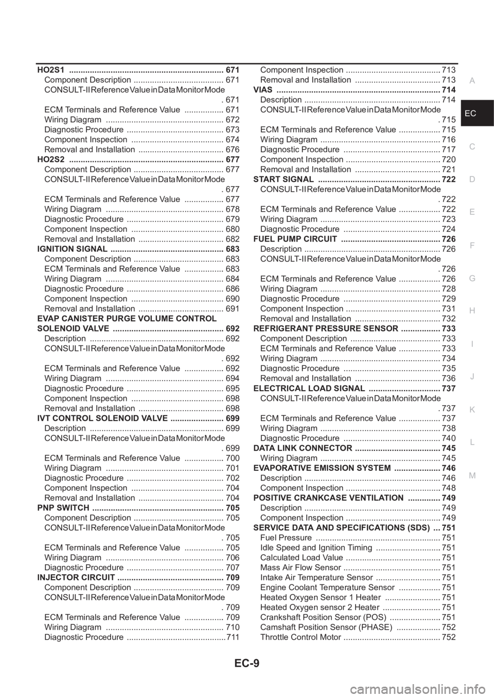
EC-9
C
D
E
F
G
H
I
J
K
L
M
ECA HO2S1 .................................................................... 671
Component Description ........................................ 671
CONSULT-II Reference Value in Data Monitor Mode
. 671
ECM Terminals and Reference Value .................. 671
Wiring Diagram .................................................... 672
Diagnostic Procedure ........................................... 673
Component Inspection ......................................... 674
Removal and Installation ...................................... 676
HO2S2 .................................................................... 677
Component Description ........................................ 677
CONSULT-II Reference Value in Data Monitor Mode
. 677
ECM Terminals and Reference Value .................. 677
Wiring Diagram .................................................... 678
Diagnostic Procedure ........................................... 679
Component Inspection ......................................... 680
Removal and Installation ...................................... 682
IGNITION SIGNAL .................................................. 683
Component Description ........................................ 683
ECM Terminals and Reference Value .................. 683
Wiring Diagram .................................................... 684
Diagnostic Procedure ........................................... 686
Component Inspection ......................................... 690
Removal and Installation ...................................... 691
EVAP CANISTER PURGE VOLUME CONTROL
SOLENOID VALVE ................................................. 692
Description ........................................................... 692
CONSULT-II Reference Value in Data Monitor Mode
. 692
ECM Terminals and Reference Value .................. 692
Wiring Diagram .................................................... 694
Diagnostic Procedure ........................................... 695
Component Inspection ......................................... 698
Removal and Installation ...................................... 698
IVT CONTROL SOLENOID VALVE ........................ 699
Description ........................................................... 699
CONSULT-II Reference Value in Data Monitor Mode
. 699
ECM Terminals and Reference Value .................. 700
Wiring Diagram .................................................... 701
Diagnostic Procedure ........................................... 702
Component Inspection ......................................... 704
Removal and Installation ...................................... 704
PNP SWITCH .......................................................... 705
Component Description ........................................ 705
CONSULT-II Reference Value in Data Monitor Mode
. 705
ECM Terminals and Reference Value .................. 705
Wiring Diagram ...................................................
. 706
Diagnostic Procedure ........................................... 707
INJECTOR CIRCUIT ............................................... 709
Component Description ........................................ 709
CONSULT-II Reference Value in Data Monitor Mode
. 709
ECM Terminals and Reference Value .................. 709
Wiring Diagram .................................................... 710
Diagnostic Procedure ............................................ 711Component Inspection ..........................................713
Removal and Installation ......................................713
VIAS ........................................................................714
Description ............................................................714
CONSULT-II Reference Value in Data Monitor Mode
.715
ECM Terminals and Reference Value ...................715
Wiring Diagram .....................................................716
Diagnostic Procedure ...........................................717
Component Inspection ..........................................720
Removal and Installation ......................................721
START SIGNAL ......................................................722
CONSULT-II Reference Value in Data Monitor Mode
.722
ECM Terminals and Reference Value ...................722
Wiring Diagram .....................................................723
Diagnostic Procedure ...........................................724
FUEL PUMP CIRCUIT ............................................726
Description ............................................................726
CONSULT-II Reference Value in Data Monitor Mode
.726
ECM Terminals and Reference Value ...................726
Wiring Diagram .....................................................728
Diagnostic Procedure ...........................................729
Component Inspection ..........................................731
Removal and Installation ......................................732
REFRIGERANT PRESSURE SENSOR ..................733
Component Description ........................................733
ECM Terminals and Reference Value ...................733
Wiring Diagram .....................................................734
Diagnostic Procedure ...........................................735
Removal and Installation ......................................736
ELECTRICAL LOAD SIGNAL ................................737
CONSULT-II Reference Value in Data Monitor Mode
.737
ECM Terminals and Reference Value ...................737
Wiring Diagram .....................................................738
Diagnostic Procedure ...........................................740
DATA LINK CONNECTOR ......................................745
Wiring Diagram .....................................................745
EVAPORATIVE EMISSION SYSTEM .....................746
Description ...................................................
.........746
Component Inspection ..........................................748
POSITIVE CRANKCASE VENTILATION ...............749
Description ............................................................749
Component Inspection ..........................................749
SERVICE DATA AND SPECIFICATIONS (SDS) ....751
Fuel Pressure .......................................................751
Idle Speed and Ignition Timing .............................751
Calculated Load Value ..........................................751
Mass Air Flow Sensor ...........................................751
Intake Air Temperature Sensor .............................751
Engine Coolant Temperature Sensor ...................751
Heated Oxygen Sensor 1 Heater .........................751
Heated Oxygen sensor 2 Heater ..........................751
Crankshaft Position Sensor (POS) .......................751
Camshaft Position Sensor (PHASE) ....................752
Throttle Control Motor ...........................................752
Page 364 of 3833
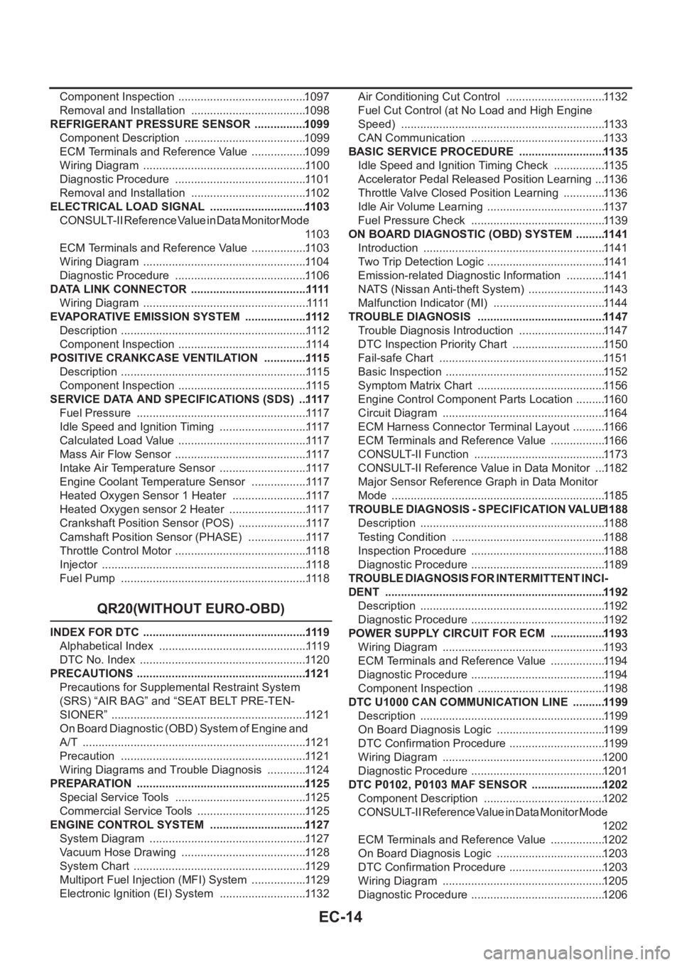
EC-14
Component Inspection .........................................1097
Removal and Installation .....................................1098
REFRIGERANT PRESSURE SENSOR .................1099
Component Description .......................................1099
ECM Terminals and Reference Value ..................1099
Wiring Diagram ....................................................11 0 0
Diagnostic Procedure ..........................................11 0 1
Removal and Installation .....................................11 0 2
ELECTRICAL LOAD SIGNAL ...............................110 3
CONSULT-II Reference Value in Data Monitor Mode
11 0 3
ECM Terminals and Reference Value ..................11 0 3
Wiring Diagram ....................................................11 0 4
Diagnostic Procedure ..........................................11 0 6
DATA LINK CONNECTOR .....................................1111
Wiring Diagram ....................................................1111
EVAPORATIVE EMISSION SYSTEM ....................111 2
Description ...........................................................111 2
Component Inspection .........................................111 4
POSITIVE CRANKCASE VENTILATION ..............111 5
Description ...........................................................111 5
Component Inspection .........................................111 5
SERVICE DATA AND SPECIFICATIONS (SDS) ...111 7
Fuel Pressure ......................................................111 7
Idle Speed and Ignition Timing ............................111 7
Calculated Load Value .........................................111 7
Mass Air Flow Sensor ..........................................111 7
Intake Air Temperature Sensor ............................111 7
Engine Coolant Temperature Sensor ..................111 7
Heated Oxygen Sensor 1 Heater ........................111 7
Heated Oxygen sensor 2 Heater .........................111 7
Crankshaft Position Sensor (POS) ......................111 7
Camshaft Position Sensor (PHASE) ...................111 7
Throttle Control Motor ..........................................111 8
Injector .................................................................111 8
Fuel Pump ...........................................................111 8
QR20(WITHOUT EURO-OBD)
INDEX FOR DTC ....................................................111 9
Alphabetical Index ...............................................111 9
DTC No. Index .....................................................11 2 0
PRECAUTIONS ......................................................112 1
Precautions for Supplemental Restraint System
(SRS) “AIR BAG” and “SEAT BELT PRE-TEN-
SIONER” ..............................................................11 2 1
On Board Diagnostic (OBD) System of Engine and
A/T .......................................................................11 2 1
Precaution ...........................................................11 2 1
Wiring Diagrams and Trouble Diagnosis .............11 2 4
PREPARATION ......................................................112 5
Special Service Tools .......................................... 11 2 5
Commercial Service Tools ...................................11 2 5
ENGINE CONTROL SYSTEM ...............................112 7
System Diagram ..................................................11 2 7
Vacuum Hose Drawing ........................................11 2 8
System Chart .......................................................11 2 9
Multiport Fuel Injection (MFI) System ..................11 2 9
Electronic Ignition (EI) System ............................11 3 2Air Conditioning Cut Control ................................11 3 2
Fuel Cut Control (at No Load and High Engine
Speed) .................................................................11 3 3
CAN Communication ...........................................11 3 3
BASIC SERVICE PROCEDURE ............................11 35
Idle Speed and Ignition Timing Check .................11 3 5
Accelerator Pedal Released Position Learning ....11 3 6
Throttle Valve Closed Position Learning ..............11 3 6
Idle Air Volume Learning ......................................11 3 7
Fuel Pressure Check ...........................................11 3 9
ON BOARD DIAGNOSTIC (OBD) SYSTEM ..........11 41
Introduction ..........................................................11 4 1
Two Trip Detection Logic ......................................11 4 1
Emission-related Diagnostic Information .............11 4 1
NATS (Nissan Anti-theft System) .........................11 4 3
Malfunction Indicator (MI) ....................................11 4 4
TROUBLE DIAGNOSIS .........................................11 47
Trouble Diagnosis Introduction ............................11 4 7
DTC Inspection Priority Chart ..............................11 5 0
Fail-safe Chart .....................................................11 5 1
Basic Inspection ...................................................11 5 2
Symptom Matrix Chart .........................................11 5 6
Engine Control Component Parts Location ..........11 6 0
Circuit Diagram ....................................................11 6 4
ECM Harness Connector Terminal Layout ...........11 6 6
ECM Terminals and Reference Value ..................11 6 6
CONSULT-II Function ..........................................
11 7 3
CONSULT-II Reference Value in Data Monitor ....11 8 2
Major Sensor Reference Graph in Data Monitor
Mode ....................................................................11 8 5
TROUBLE DIAGNOSIS - SPECIFICATION VALUE 11 88
Description ...........................................................11 8 8
Testing Condition .................................................11 8 8
Inspection Procedure ........................................... 11 8 8
Diagnostic Procedure ........................................... 11 8 9
TROUBLE DIAGNOSIS FOR INTERMITTENT INCI-
DENT ......................................................................11 92
Description ...........................................................11 9 2
Diagnostic Procedure ........................................... 11 9 2
POWER SUPPLY CIRCUIT FOR ECM ..................11 93
Wiring Diagram ....................................................11 9 3
ECM Terminals and Reference Value ..................11 9 4
Diagnostic Procedure ........................................... 11 9 4
Component Inspection .........................................11 9 8
DTC U1000 CAN COMMUNICATION LINE ...........11 99
Description ...........................................................11 9 9
On Board Diagnosis Logic ...................................11 9 9
DTC Confirmation Procedure ...............................11 9 9
Wiring Diagram ....................................................1200
Diagnostic Procedure ........................................... 1201
DTC P0102, P0103 MAF SENSOR ........................1202
Component Description .......................................1202
CONSULT-II Reference Value in Data Monitor Mode
1202
ECM Terminals and Reference Value ..................1202
On Board Diagnosis Logic ...................................1203
DTC Confirmation Procedure ...............................1203
Wiring Diagram ....................................................1205
Diagnostic Procedure ........................................... 1206
Page 367 of 3833
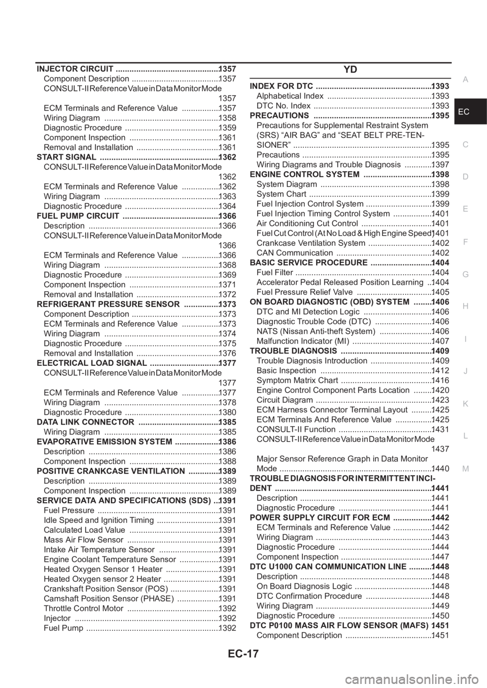
EC-17
C
D
E
F
G
H
I
J
K
L
M
ECA INJECTOR CIRCUIT ..............................................1357
Component Description .......................................1357
CONSULT-II Reference Value in Data Monitor Mode
1357
ECM Terminals and Reference Value .................1357
Wiring Diagram ...................................................1358
Diagnostic Procedure ..........................................1359
Component Inspection ........................................1361
Removal and Installation .....................................1361
START SIGNAL .....................................................1362
CONSULT-II Reference Value in Data Monitor Mode
1362
ECM Terminals and Reference Value .................1362
Wiring Diagram ...................................................1363
Diagnostic Procedure ..........................................1364
FUEL PUMP CIRCUIT ...........................................1366
Description ..........................................................1366
CONSULT-II Reference Value in Data Monitor Mode
1366
ECM Terminals and Reference Value .................1366
Wiring Diagram ...................................................1368
Diagnostic Procedure ..........................................1369
Component Inspection ........................................1371
Removal and Installation .....................................1372
REFRIGERANT PRESSURE SENSOR ................1373
Component Description .......................................1373
ECM Terminals and Reference Value .................1373
Wiring Diagram ...................................................1374
Diagnostic Procedure ..........................................1375
Removal and Installation .....................................1376
ELECTRICAL LOAD SIGNAL ...............................1377
CONSULT-II Reference Value in Data Monitor Mode
1377
ECM Terminals and Reference Value .................1377
Wiring Diagram ...................................................1378
Diagnostic Procedure ..........................................1380
DATA LINK CONNECTOR ....................................1385
Wiring Diagram ...................................................1385
EVAPORATIVE EMISSION SYSTEM ....................1386
Description ..........................................................1386
Component Inspection ........................................1388
POSITIVE CRANKCASE VENTILATION ..............1389
Description ..........................................................1389
Component Inspection ........................................1389
SERVICE DATA AND SPECIFICATIONS (SDS) ...1391
Fuel Pressure ......................................................1391
Idle Speed and Ignition Timing ............................1391
Calculated Load Value ........................................1391
Mass Air Flow Sensor .........................................1391
Intake Air Temperature Sensor ...........................1391
Engine Coolant Temperature Sensor ..................1391
Heated Oxygen Sensor 1 Heater ........................1391
Heated Oxygen sensor 2 Heater .........................1391
Crankshaft Position Sensor (POS) ......................1391
Camshaft Position Sensor (PHASE) ...................1391
Throttle Control Motor ......................................... 1392
Injector ................................................................1392
Fuel Pump ...........................................................1392
YD
INDEX FOR DTC ....................................................1393
Alphabetical Index ...............................................1393
DTC No. Index .....................................................1393
PRECAUTIONS .....................................................1395
Precautions for Supplemental Restraint System
(SRS) “AIR BAG” and “SEAT BELT PRE-TEN-
SIONER” ..............................................................1395
Precautions ..........................................................1395
Wiring Diagrams and Trouble Diagnosis .............1397
ENGINE CONTROL SYSTEM ...............................1398
System Diagram ..................................................1398
System Chart .......................................................1399
Fuel Injection Control System ..............................1399
Fuel Injection Timing Control System ..................1401
Air Conditioning Cut Control ................................1401
F u e l C u t C o n t r o l ( A t N o L o a d & H i g h E n g i n e S p e e d ) 1401
Crankcase Ventilation System .............................1402
CAN Communication ...........................................1402
BASIC SERVICE PROCEDURE ............................1404
Fuel Filter .............................................................1404
Accelerator Pedal Released Position Learning ...1404
Fuel Pressure Relief Valve ..................................1405
ON BOARD DIAGNOSTIC (OBD) SYSTEM .........1406
DTC and MI Detection Logic ...............................1406
Diagnostic Trouble Code (DTC) ..........................1406
NATS (Nissan Anti-theft System) ........................1406
Malfunction Indicator (MI) ....................................1407
TROUBLE DIAGNOSIS .........................................1409
Trouble Diagnosis Introduction ............................1409
Basic Inspection ..................................................1412
Symptom Matrix Chart .........................................1416
Engine Control Component Parts Location .........1420
Circuit Diagram ....................................................1423
ECM Harness Connector Terminal Layout ..........1425
ECM Terminals And Reference Value .................1425
CONSULT-II Function ..........................................1431
CONSULT-II Reference Value in Data Monitor Mode
1437
Major Sensor Reference Graph in Data Monitor
Mode ....................................................................1440
TROUBLE DIAGNOSIS FOR INTERMITTENT INCI-
DENT ......................................................................1441
Description ...........................................................1441
Diagnostic Procedure ..........................................1441
POWER SUPPLY CIRCUIT FOR ECM ..................1442
ECM Terminals and Reference Value ..................1442
Wiring Diagram ....................................................1443
Diagnostic Procedure ..........................................1444
Component Inspection .........................................1447
DTC U1000 CAN COMMUNICATION LINE ...........1448
Description ...........................................................1448
On Board Diagnosis Logic ...................................1448
DTC Confirmation Procedure ..............................1448
Wiring Diagram ....................................................1449
Diagnostic Procedure ..........................................1450
DTC P0100 MASS AIR FLOW SENSOR (MAFS) .1451
Component Description .......................................1451
Page 368 of 3833
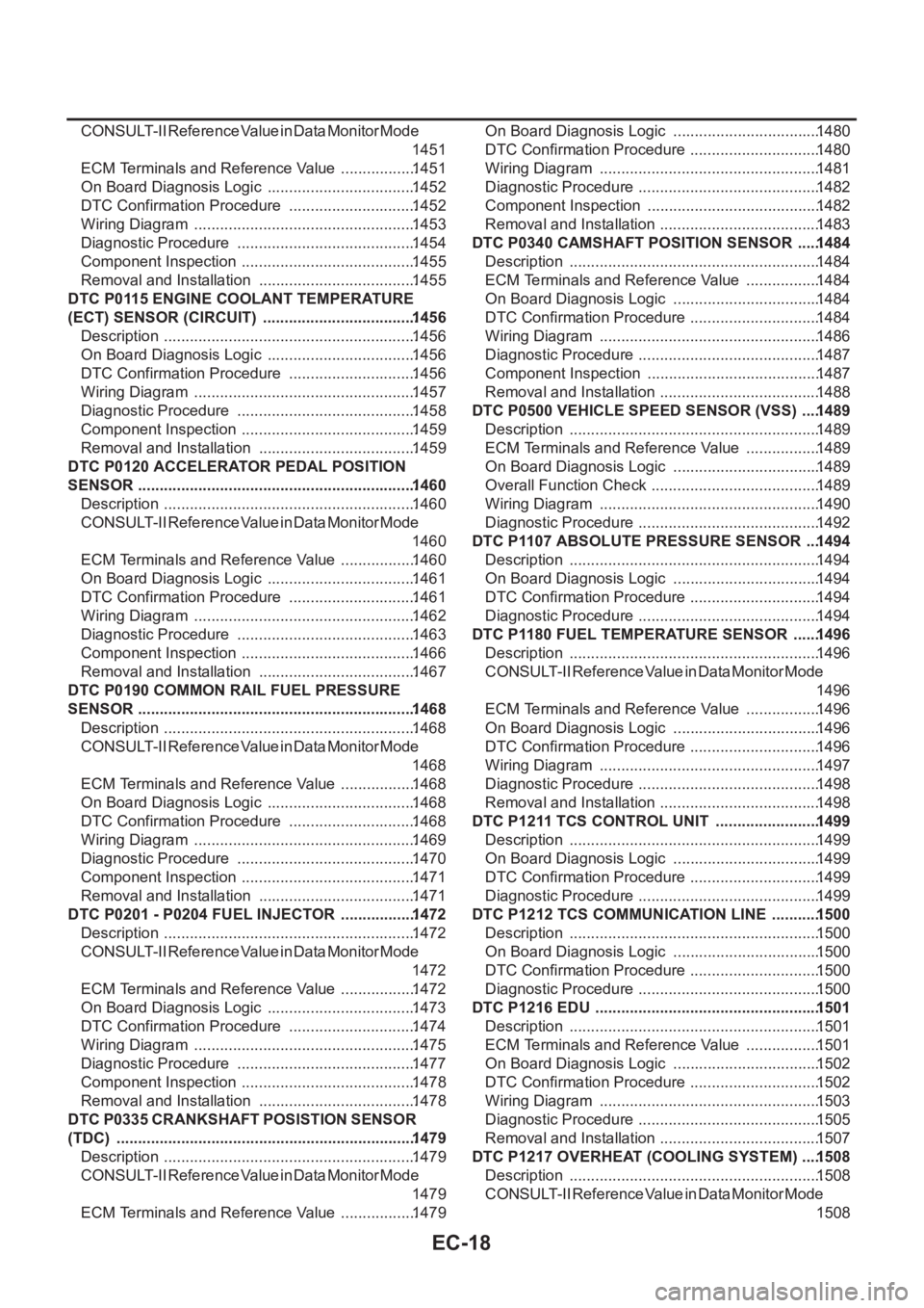
EC-18
CONSULT-II Reference Value in Data Monitor Mode
1451
ECM Terminals and Reference Value ..................1451
On Board Diagnosis Logic ...................................1452
DTC Confirmation Procedure ..............................1452
Wiring Diagram ....................................................1453
Diagnostic Procedure ..........................................1454
Component Inspection .........................................1455
Removal and Installation .....................................1455
DTC P0115 ENGINE COOLANT TEMPERATURE
(ECT) SENSOR (CIRCUIT) ....................................1456
Description ...........................................................1456
On Board Diagnosis Logic ...................................1456
DTC Confirmation Procedure ..............................1456
Wiring Diagram ....................................................1457
Diagnostic Procedure ..........................................1458
Component Inspection .........................................1459
Removal and Installation .....................................1459
DTC P0120 ACCELERATOR PEDAL POSITION
SENSOR .................................................................1460
Description ...........................................................1460
CONSULT-II Reference Value in Data Monitor Mode
1460
ECM Terminals and Reference Value ..................1460
On Board Diagnosis Logic ...................................1461
DTC Confirmation Procedure ..............................1461
Wiring Diagram ....................................................1462
Diagnostic Procedure ..........................................1463
Component Inspection .........................................1466
Removal and Installation .....................................1467
DTC P0190 COMMON RAIL FUEL PRESSURE
SENSOR .................................................................1468
Description ...........................................................1468
CONSULT-II Reference Value in Data Monitor Mode
1468
ECM Terminals and Reference Value ..................1468
On Board Diagnosis Logic ...................................1468
DTC Confirmation Procedure ..............................1468
Wiring Diagram ....................................................1469
Diagnostic Procedure ..........................................1470
Component Inspection .........................................1471
Removal and Installation .....................................1471
DTC P0201 - P0204 FUEL INJECTOR ..................1472
Description ...........................................................1472
CONSULT-II Reference Value in Data Monitor Mode
1472
ECM Terminals and Reference Value ..................1472
On Board Diagnosis Logic ...................................1473
DTC Confirmation Procedure ..............................1474
Wiring Diagram ....................................................1475
Diagnostic Procedure ..........................................1477
Component Inspection .........................................
1478
Removal and Installation .....................................1478
DTC P0335 CRANKSHAFT POSISTION SENSOR
(TDC) ......................................................................1479
Description ...........................................................1479
CONSULT-II Reference Value in Data Monitor Mode
1479
ECM Terminals and Reference Value ..................1479On Board Diagnosis Logic ...................................1480
DTC Confirmation Procedure ...............................1480
Wiring Diagram ....................................................1481
Diagnostic Procedure ........................................... 1482
Component Inspection .........................................1482
Removal and Installation ......................................1483
DTC P0340 CAMSHAFT POSITION SENSOR ......1484
Description ...........................................................1484
ECM Terminals and Reference Value ..................1484
On Board Diagnosis Logic ...................................1484
DTC Confirmation Procedure ...............................1484
Wiring Diagram ....................................................1486
Diagnostic Procedure ........................................... 1487
Component Inspection .........................................1487
Removal and Installation ......................................1488
DTC P0500 VEHICLE SPEED SENSOR (VSS) .....1489
Description ...........................................................1489
ECM Terminals and Reference Value ..................1489
On Board Diagnosis Logic ...................................1489
Overall Function Check ........................................1489
Wiring Diagram ....................................................1490
Diagnostic Procedure ........................................... 1492
DTC P1107 ABSOLUTE PRESSURE SENSOR ....1494
Description ...........................................................1494
On Board Diagnosis Logic ...................................1494
DTC Confirmation Procedure ...............................1494
Diagnostic Procedure ........................................... 1494
DTC P1180 FUEL TEMPERATURE SENSOR .......1496
Description ...........................................................1496
CONSULT-II Reference Value in Data Monitor Mode
1496
ECM Terminals and Reference Value ..................1496
On Board Diagnosis Logic ...................................1496
DTC Confirmation Procedure ...............................1496
Wiring Diagram ....................................................1497
Diagnostic Procedure ........................................... 1498
Removal and Installation ......................................1498
DTC P1211 TCS CONTROL UNIT .........................1499
Description ...................................................
........1499
On Board Diagnosis Logic ...................................1499
DTC Confirmation Procedure ...............................1499
Diagnostic Procedure ........................................... 1499
DTC P1212 TCS COMMUNICATION LINE ............1500
Description ...........................................................1500
On Board Diagnosis Logic ...................................1500
DTC Confirmation Procedure ...............................1500
Diagnostic Procedure ........................................... 1500
DTC P1216 EDU .....................................................1501
Description ...........................................................1501
ECM Terminals and Reference Value ..................1501
On Board Diagnosis Logic ...................................1502
DTC Confirmation Procedure ...............................1502
Wiring Diagram ....................................................1503
Diagnostic Procedure ........................................... 1505
Removal and Installation ......................................1507
DTC P1217 OVERHEAT (COOLING SYSTEM) .....1508
Description ...........................................................1508
CONSULT-II Reference Value in Data Monitor Mode
1508
Page 369 of 3833
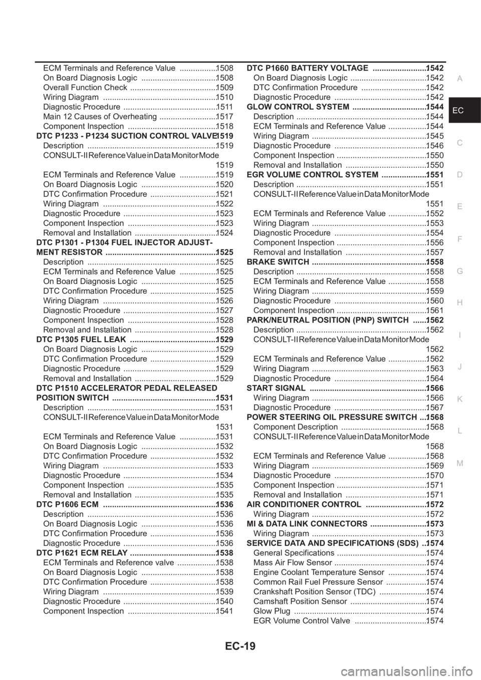
EC-19
C
D
E
F
G
H
I
J
K
L
M
ECA ECM Terminals and Reference Value .................1508
On Board Diagnosis Logic ..................................1508
Overall Function Check .......................................1509
Wiring Diagram ...................................................1510
Diagnostic Procedure ..........................................1511
Main 12 Causes of Overheating ..........................1517
Component Inspection ........................................1518
DTC P1233 - P1234 SUCTION CONTROL VALVE 1519
Description ..........................................................1519
CONSULT-II Reference Value in Data Monitor Mode
1519
ECM Terminals and Reference Value .................1519
On Board Diagnosis Logic ..................................1520
DTC Confirmation Procedure ..............................1521
Wiring Diagram ...................................................1522
Diagnostic Procedure ..........................................1523
Component Inspection ........................................1523
Removal and Installation .....................................1524
DTC P1301 - P1304 FUEL INJECTOR ADJUST-
MENT RESISTOR .................................................. 1525
Description ..........................................................1525
ECM Terminals and Reference Value .................1525
On Board Diagnosis Logic ..................................1525
DTC Confirmation Procedure ..............................1525
Wiring Diagram ...................................................1526
Diagnostic Procedure ..........................................1527
Component Inspection ........................................1528
Removal and Installation .....................................1528
DTC P1305 FUEL LEAK .......................................1529
On Board Diagnosis Logic ..................................1529
DTC Confirmation Procedure ..............................1529
Diagnostic Procedure ..........................................1529
Removal and Installation .....................................1529
DTC P1510 ACCELERATOR PEDAL RELEASED
POSITION SWITCH ...............................................1531
Description ..........................................................1531
CONSULT-II Reference Value in Data Monitor Mode
1531
ECM Terminals and Reference Value .................1531
On Board Diagnosis Logic ..................................1532
DTC Confirmation Procedure ..............................1532
Wiring Diagram ...................................................1533
Diagnostic Procedure ..........................................1534
Component Inspection ........................................1535
Removal and Installation .....................................1535
DTC P1606 ECM ...................................................1536
Description ..........................................................1536
On Board Diagnosis Logic ..................................1536
DTC Confirmation Procedure ..............................
1536
Diagnostic Procedure ..........................................1536
DTC P1621 ECM RELAY .......................................1538
ECM Terminals and Reference valve ..................1538
On Board Diagnosis Logic ..................................1538
DTC Confirmation Procedure ..............................1538
Wiring Diagram ...................................................1539
Diagnostic Procedure ..........................................1540
Component Inspection ........................................1541DTC P1660 BATTERY VOLTAGE .........................1542
On Board Diagnosis Logic ...................................1542
DTC Confirmation Procedure ..............................1542
Diagnostic Procedure ..........................................1542
GLOW CONTROL SYSTEM ..................................1544
Description ...........................................................1544
ECM Terminals and Reference Value ..................1544
Wiring Diagram ....................................................1545
Diagnostic Procedure ..........................................1546
Component Inspection .........................................1550
Removal and Installation .....................................1550
EGR VOLUME CONTROL SYSTEM .....................1551
Description ...........................................................1551
CONSULT-II Reference Value in Data Monitor Mode
1551
ECM Terminals and Reference Value ..................1552
Wiring Diagram ....................................................1553
Diagnostic Procedure ..........................................1554
Component Inspection .........................................1556
Removal and Installation .....................................1557
BRAKE SWITCH ....................................................1558
Description ...........................................................1558
ECM Terminals and Reference Value ..................1558
Wiring Diagram ....................................................1559
Diagnostic Procedure ..........................................1560
Component Inspection .........................................1561
PARK/NEUTRAL POSITION (PNP) SWITCH .......1562
Description ...........................................................1562
CONSULT-II Reference Value in Data Monitor Mode
1562
ECM Terminals and Reference Value ..................1562
Wiring Diagram ....................................................1563
Diagnostic Procedure ..........................................1564
START SIGNAL .....................................................1566
Wiring Diagram ....................................................1566
Diagnostic Procedure ..........................................1567
POWER STEERING OIL PRESSURE SWITCH ....1568
Component Description .......................................1568
CONSULT-II Reference Value in Data Monitor Mode
1568
ECM Terminals and Reference Value ..................1568
Wiring Diagram ....................................................1569
Diagnostic Procedure ..........................................1570
Component Inspection .........................................1571
Removal and Installation .....................................1571
AIR CONDITIONER CONTROL ............................1572
Wiring Diagram ....................................................1572
MI & DATA LINK CONNECTORS ..........................1573
Wiring Diagram ....................................................1573
SERVICE DATA AND SPECIFICATIONS (SDS) ...1574
General Specifications ......................................... 1574
Mass Air Flow Sensor ..........................................1574
Engine Coolant Temperature Sensor ..................1574
Common Rail Fuel Pressure Sensor ...................1574
Crankshaft Position Sensor (TDC) ......................1574
Camshaft Position Sensor ...................................1574
Glow Plug ............................................................1574
EGR Volume Control Valve .................................1574
Page 376 of 3833

EC-26
[QR25(WITH EURO-OBD)]
PRECAUTIONS
●Do not disassemble ECM.
●If a battery terminal is disconnected, the memory will return
to the ECM value.
The ECM will now start to self-control at its initial value.
Engine operation can vary slightly when the terminal is dis-
connected. However, this is not an indication of a malfunc-
tion. Do not replace parts because of a slight variation.
●When connecting ECM harness connector, fasten it
securely with a lever as far as it will go as shown at right.
●When connecting or disconnecting pin connectors into or
from ECM, take care not to damage pin terminals (bend or
break).
Make sure that there are not any bends or breaks on ECM
pin terminal, when connecting pin connectors.
●Securely connect ECM harness connectors.
A poor connection can cause an extremely high (surge)
voltage to develop in coil and condenser, thus resulting in
damage to ICs.
●Keep engine control system harness at least 10 cm (4 in)
away from adjacent harness, to prevent engine control sys-
tem malfunctions due to receiving external noise, degraded
operation of ICs, etc.
●Keep engine control system parts and harness dry.
●Before replacing ECM, perform “ECM Terminals and Refer-
ence Value” inspection and make sure ECM functions prop-
erly. Refer to EC-819
.
●Handle mass air flow sensor carefully to avoid damage.
●Do not disassemble mass air flow sensor.
●Do not clean mass air flow sensor with any type of deter-
gent.
●Do not disassemble electric throttle control actuator.
●Even a slight leak in the air intake system can cause seri-
ous incidents.
●Do not shock or jar the camshaft position sensor (PHASE),
crankshaft position sensor (POS).
SEF707Y
SEF908W
PBIB0090E
MEF040D