Shaft NISSAN X-TRAIL 2001 Service Owners Manual
[x] Cancel search | Manufacturer: NISSAN, Model Year: 2001, Model line: X-TRAIL, Model: NISSAN X-TRAIL 2001Pages: 3833, PDF Size: 39.49 MB
Page 225 of 3833
PRIMARY TIMING CHAIN
EM-175
[YD22DDTi]
C
D
E
F
G
H
I
J
K
L
MA
EM
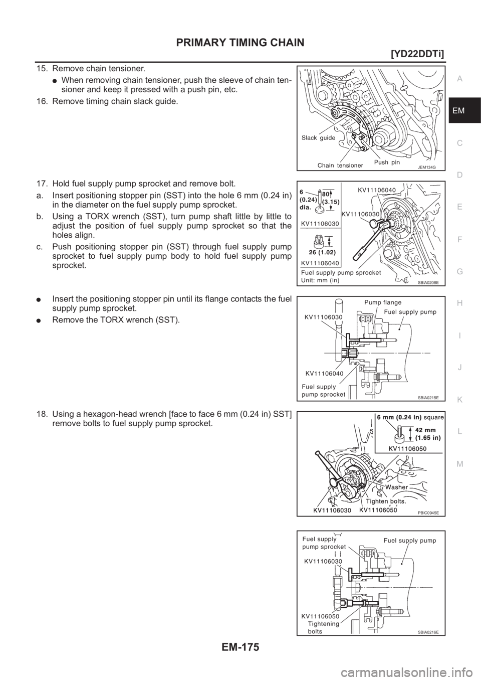
15. Remove chain tensioner.
●When removing chain tensioner, push the sleeve of chain ten-
sioner and keep it pressed with a push pin, etc.
16. Remove timing chain slack guide.
17. Hold fuel supply pump sprocket and remove bolt.
a. Insert positioning stopper pin (SST) into the hole 6 mm (0.24 in)
in the diameter on the fuel supply pump sprocket.
b. Using a TORX wrench (SST), turn pump shaft little by little to
adjust the position of fuel supply pump sprocket so that the
holes align.
c. Push positioning stopper pin (SST) through fuel supply pump
sprocket to fuel supply pump body to hold fuel supply pump
sprocket.
●Insert the positioning stopper pin until its flange contacts the fuel
supply pump sprocket.
●Remove the TORX wrench (SST).
18. Using a hexagon-head wrench [face to face 6 mm (0.24 in) SST]
remove bolts to fuel supply pump sprocket.
JEM134G
SBIA0208E
SBIA0215E
PBIC0945E
SBIA0216E
Page 226 of 3833
EM-176
[YD22DDTi]
PRIMARY TIMING CHAIN
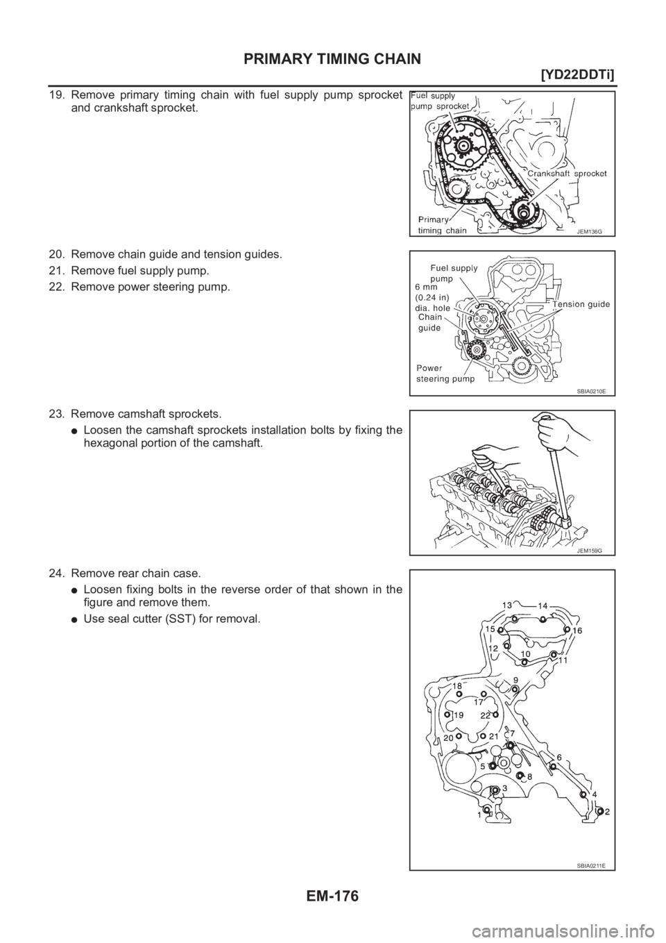
19. Remove primary timing chain with fuel supply pump sprocket
and crankshaft sprocket.
20. Remove chain guide and tension guides.
21. Remove fuel supply pump.
22. Remove power steering pump.
23. Remove camshaft sprockets.
●Loosen the camshaft sprockets installation bolts by fixing the
hexagonal portion of the camshaft.
24. Remove rear chain case.
●Loosen fixing bolts in the reverse order of that shown in the
figure and remove them.
●Use seal cutter (SST) for removal.
JEM136G
SBIA0210E
JEM159G
SBIA0211E
Page 228 of 3833
EM-178
[YD22DDTi]
PRIMARY TIMING CHAIN
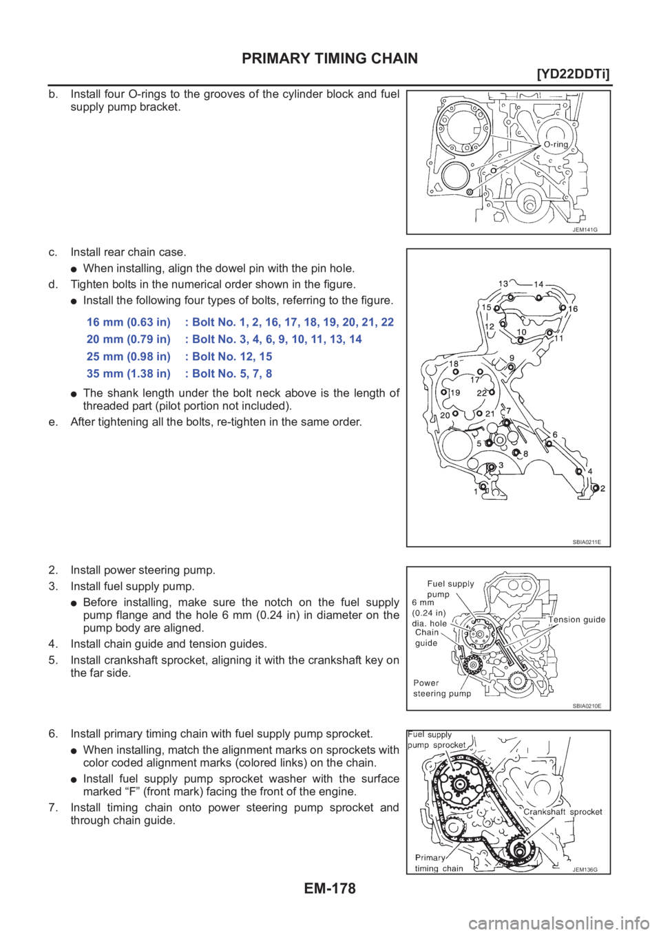
b. Install four O-rings to the grooves of the cylinder block and fuel
supply pump bracket.
c. Install rear chain case.
●When installing, align the dowel pin with the pin hole.
d. Tighten bolts in the numerical order shown in the figure.
●Install the following four types of bolts, referring to the figure.
●The shank length under the bolt neck above is the length of
threaded part (pilot portion not included).
e. After tightening all the bolts, re-tighten in the same order.
2. Install power steering pump.
3. Install fuel supply pump.
●Before installing, make sure the notch on the fuel supply
pump flange and the hole 6 mm (0.24 in) in diameter on the
pump body are aligned.
4. Install chain guide and tension guides.
5. Install crankshaft sprocket, aligning it with the crankshaft key on
the far side.
6. Install primary timing chain with fuel supply pump sprocket.
●When installing, match the alignment marks on sprockets with
color coded alignment marks (colored links) on the chain.
●Install fuel supply pump sprocket washer with the surface
marked “F” (front mark) facing the front of the engine.
7. Install timing chain onto power steering pump sprocket and
through chain guide.
JEM141G
16 mm (0.63 in) : Bolt No. 1, 2, 16, 17, 18, 19, 20, 21, 22
20 mm (0.79 in) : Bolt No. 3, 4, 6, 9, 10, 11, 13, 14
25 mm (0.98 in) : Bolt No. 12, 15
35 mm (1.38 in) : Bolt No. 5, 7, 8
SBIA0211E
SBIA0210E
JEM136G
Page 229 of 3833
PRIMARY TIMING CHAIN
EM-179
[YD22DDTi]
C
D
E
F
G
H
I
J
K
L
MA
EM
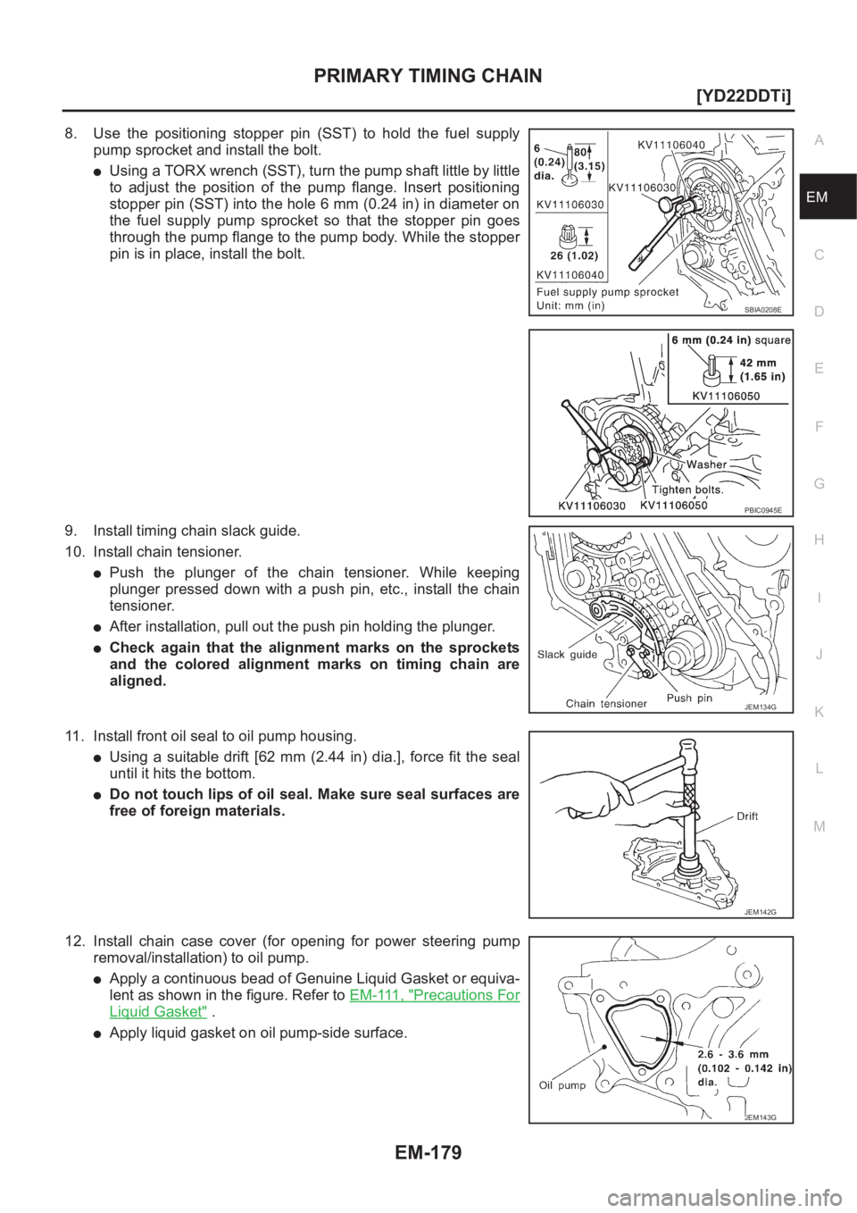
8. Use the positioning stopper pin (SST) to hold the fuel supply
pump sprocket and install the bolt.
●Using a TORX wrench (SST), turn the pump shaft little by little
to adjust the position of the pump flange. Insert positioning
stopper pin (SST) into the hole 6 mm (0.24 in) in diameter on
the fuel supply pump sprocket so that the stopper pin goes
through the pump flange to the pump body. While the stopper
pin is in place, install the bolt.
9. Install timing chain slack guide.
10. Install chain tensioner.
●Push the plunger of the chain tensioner. While keeping
plunger pressed down with a push pin, etc., install the chain
tensioner.
●After installation, pull out the push pin holding the plunger.
●Check again that the alignment marks on the sprockets
and the colored alignment marks on timing chain are
aligned.
11. Install front oil seal to oil pump housing.
●Using a suitable drift [62 mm (2.44 in) dia.], force fit the seal
until it hits the bottom.
●Do not touch lips of oil seal. Make sure seal surfaces are
free of foreign materials.
12. Install chain case cover (for opening for power steering pump
removal/installation) to oil pump.
●Apply a continuous bead of Genuine Liquid Gasket or equiva-
lent as shown in the figure. Refer to EM-111, "
Precautions For
Liquid Gasket" .
●Apply liquid gasket on oil pump-side surface.
SBIA0208E
PBIC0945E
JEM134G
JEM142G
JEM143G
Page 230 of 3833
EM-180
[YD22DDTi]
PRIMARY TIMING CHAIN
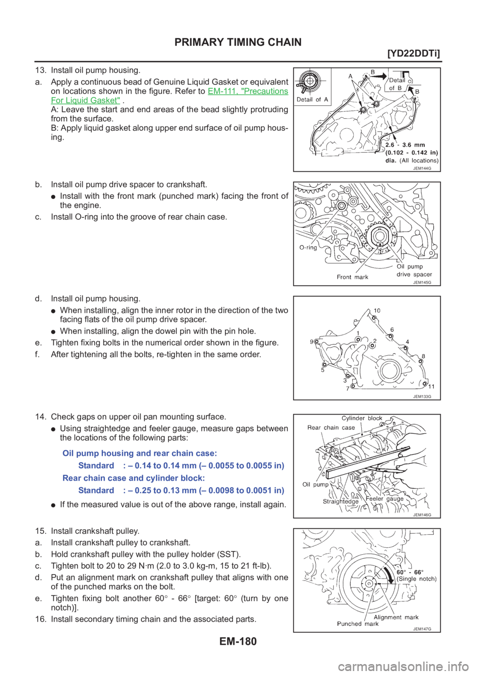
13. Install oil pump housing.
a. Apply a continuous bead of Genuine Liquid Gasket or equivalent
on locations shown in the figure. Refer to EM-111, "
Precautions
For Liquid Gasket" .
A: Leave the start and end areas of the bead slightly protruding
from the surface.
B: Apply liquid gasket along upper end surface of oil pump hous-
ing.
b. Install oil pump drive spacer to crankshaft.
●Install with the front mark (punched mark) facing the front of
the engine.
c. Install O-ring into the groove of rear chain case.
d. Install oil pump housing.
●When installing, align the inner rotor in the direction of the two
facing flats of the oil pump drive spacer.
●When installing, align the dowel pin with the pin hole.
e. Tighten fixing bolts in the numerical order shown in the figure.
f. After tightening all the bolts, re-tighten in the same order.
14. Check gaps on upper oil pan mounting surface.
●Using straightedge and feeler gauge, measure gaps between
the locations of the following parts:
●If the measured value is out of the above range, install again.
15. Install crankshaft pulley.
a. Install crankshaft pulley to crankshaft.
b. Hold crankshaft pulley with the pulley holder (SST).
c. Tighten bolt to 20 to 29 N·m (2.0 to 3.0 kg-m, 15 to 21 ft-lb).
d. Put an alignment mark on crankshaft pulley that aligns with one
of the punched marks on the bolt.
e. Tighten fixing bolt another 60° - 66° [target: 60° (turn by one
notch)].
16. Install secondary timing chain and the associated parts.
JEM144G
JEM145G
JEM133G
Oil pump housing and rear chain case:
Standard : – 0.14 to 0.14 mm (– 0.0055 to 0.0055 in)
Rear chain case and cylinder block:
Standard : – 0.25 to 0.13 mm (– 0.0098 to 0.0051 in)
JEM146G
JEM147G
Page 233 of 3833
CYLINDER HEAD
EM-183
[YD22DDTi]
C
D
E
F
G
H
I
J
K
L
MA
EM
a. Turn the ignition switch to “OFF”.
b. Disconnect battery negative terminal.
c. Install glow plug and install all the parts removed in step 4.
d. Install fuel supply pump fuse [ENG CONT (20A)].
e. Connect battery negative terminal.
f. Using CONSULT-II make sure no error code is indicated for items of self-diagnosis.
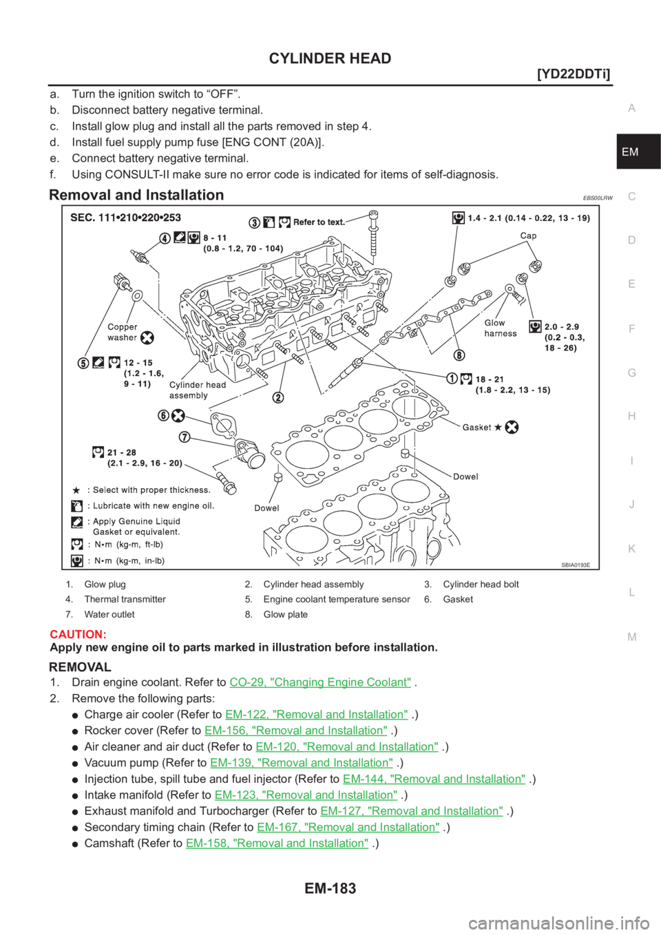
Removal and InstallationEBS00LRW
CAUTION:
Apply new engine oil to parts marked in illustration before installation.
REMOVAL
1. Drain engine coolant. Refer to CO-29, "Changing Engine Coolant" .
2. Remove the following parts:
●Charge air cooler (Refer to EM-122, "Removal and Installation" .)
●Rocker cover (Refer to EM-156, "Removal and Installation" .)
●Air cleaner and air duct (Refer to EM-120, "Removal and Installation" .)
●Vacuum pump (Refer to EM-139, "Removal and Installation" .)
●Injection tube, spill tube and fuel injector (Refer to EM-144, "Removal and Installation" .)
●Intake manifold (Refer to EM-123, "Removal and Installation" .)
●Exhaust manifold and Turbocharger (Refer to EM-127, "Removal and Installation" .)
●Secondary timing chain (Refer to EM-167, "Removal and Installation" .)
●Camshaft (Refer to EM-158, "Removal and Installation" .)
SBIA0193E
1. Glow plug 2. Cylinder head assembly 3. Cylinder head bolt
4. Thermal transmitter 5. Engine coolant temperature sensor 6. Gasket
7. Water outlet 8. Glow plate
Page 235 of 3833
CYLINDER HEAD
EM-185
[YD22DDTi]
C
D
E
F
G
H
I
J
K
L
MA
EM
INSTALLATION
Before installation, remove old liquid gasket from mating surface of all liquid gasket applied parts.
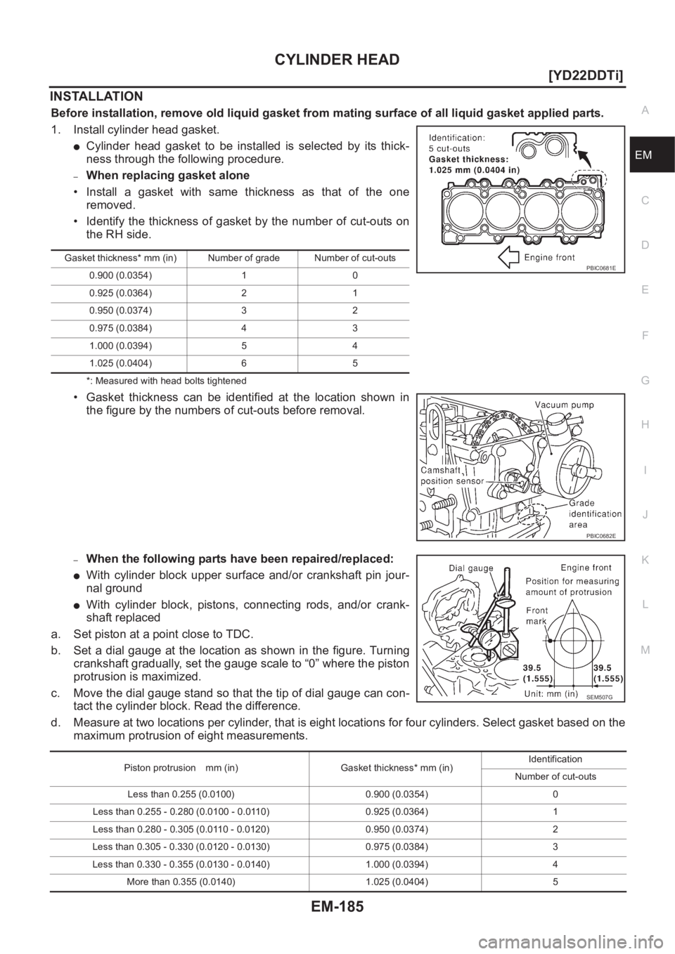
1. Install cylinder head gasket.
●Cylinder head gasket to be installed is selected by its thick-
ness through the following procedure.
–When replacing gasket alone
• Install a gasket with same thickness as that of the one
removed.
• Identify the thickness of gasket by the number of cut-outs on
the RH side.
*: Measured with head bolts tightened
• Gasket thickness can be identified at the location shown in
the figure by the numbers of cut-outs before removal.
–When the following parts have been repaired/replaced:
●With cylinder block upper surface and/or crankshaft pin jour-
nal ground
●With cylinder block, pistons, connecting rods, and/or crank-
shaft replaced
a. Set piston at a point close to TDC.
b. Set a dial gauge at the location as shown in the figure. Turning
crankshaft gradually, set the gauge scale to “0” where the piston
protrusion is maximized.
c. Move the dial gauge stand so that the tip of dial gauge can con-
tact the cylinder block. Read the difference.
d. Measure at two locations per cylinder, that is eight locations for four cylinders. Select gasket based on the
maximum protrusion of eight measurements.
Gasket thickness* mm (in) Number of grade Number of cut-outs
0.900 (0.0354) 1 0
0.925 (0.0364) 2 1
0.950 (0.0374) 3 2
0.975 (0.0384) 4 3
1.000 (0.0394) 5 4
1.025 (0.0404) 6 5PBIC0681E
PBIC0682E
SEM507G
Piston protrusion mm (in) Gasket thickness* mm (in)Identification
Number of cut-outs
Less than 0.255 (0.0100) 0.900 (0.0354) 0
Less than 0.255 - 0.280 (0.0100 - 0.0110) 0.925 (0.0364) 1
Less than 0.280 - 0.305 (0.0110 - 0.0120) 0.950 (0.0374) 2
Less than 0.305 - 0.330 (0.0120 - 0.0130) 0.975 (0.0384) 3
Less than 0.330 - 0.355 (0.0130 - 0.0140) 1.000 (0.0394) 4
More than 0.355 (0.0140) 1.025 (0.0404) 5
Page 237 of 3833
CYLINDER HEAD
EM-187
[YD22DDTi]
C
D
E
F
G
H
I
J
K
L
MA
EM
Disassembly and AssemblyEBS00LRX
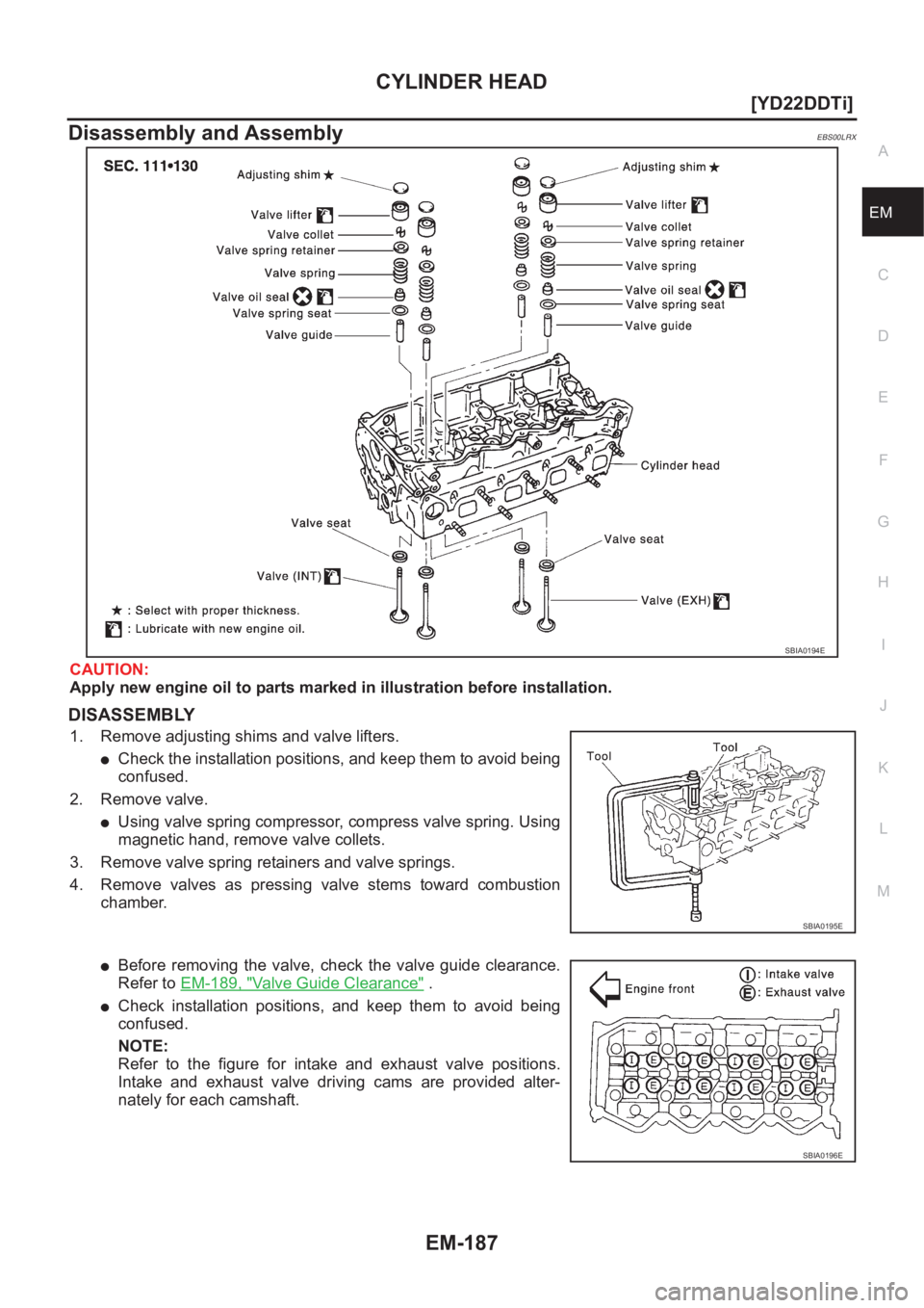
CAUTION:
Apply new engine oil to parts marked in illustration before installation.
DISASSEMBLY
1. Remove adjusting shims and valve lifters.
●Check the installation positions, and keep them to avoid being
confused.
2. Remove valve.
●Using valve spring compressor, compress valve spring. Using
magnetic hand, remove valve collets.
3. Remove valve spring retainers and valve springs.
4. Remove valves as pressing valve stems toward combustion
chamber.
●Before removing the valve, check the valve guide clearance.
Refer to EM-189, "
Valve Guide Clearance" .
●Check installation positions, and keep them to avoid being
confused.
NOTE:
Refer to the figure for intake and exhaust valve positions.
Intake and exhaust valve driving cams are provided alter-
nately for each camshaft.
SBIA0194E
SBIA0195E
SBIA0196E
Page 240 of 3833
EM-190
[YD22DDTi]
CYLINDER HEAD
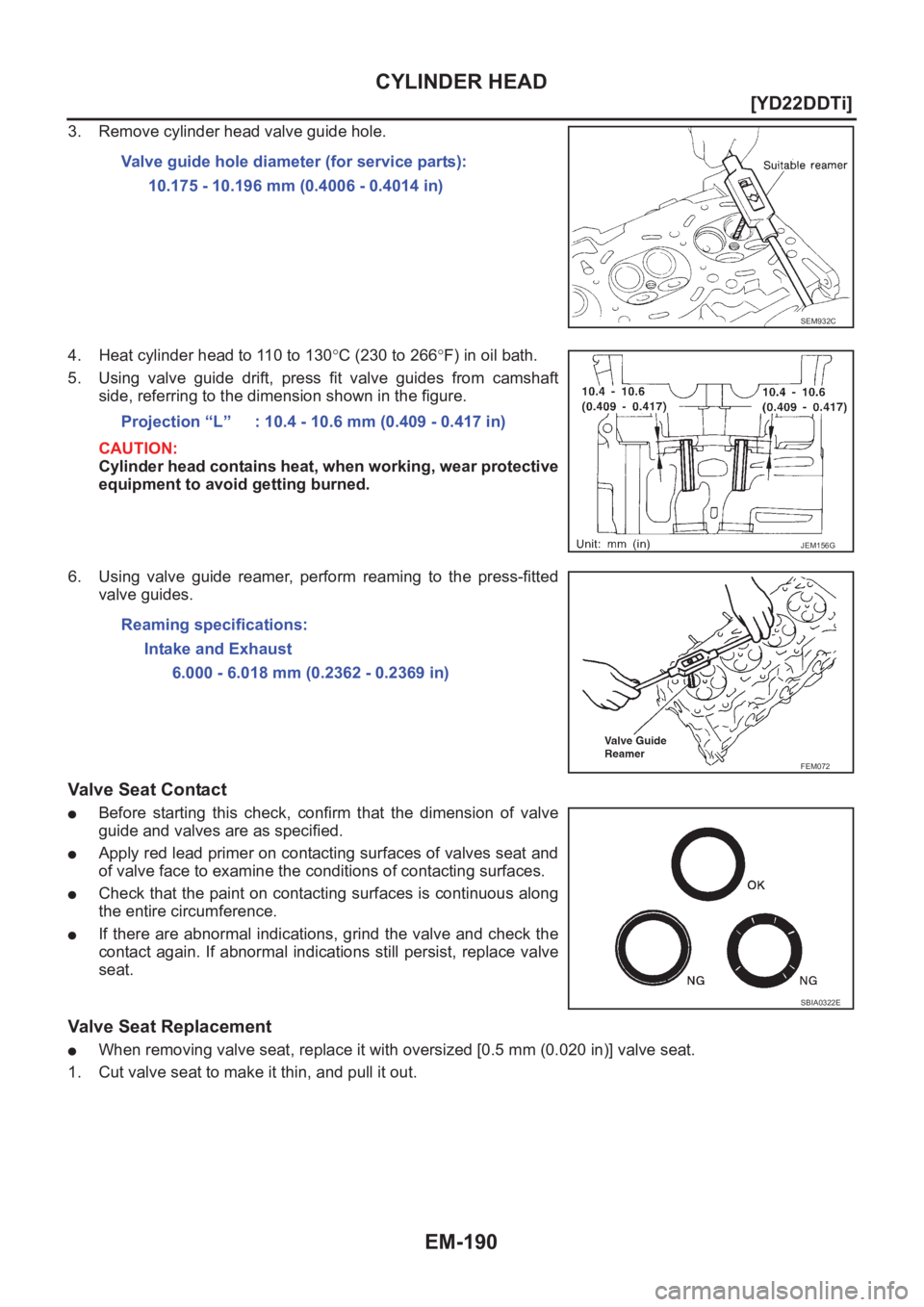
3. Remove cylinder head valve guide hole.
4. Heat cylinder head to 110 to 130°C (230 to 266°F) in oil bath.
5. Using valve guide drift, press fit valve guides from camshaft
side, referring to the dimension shown in the figure.
CAUTION:
Cylinder head contains heat, when working, wear protective
equipment to avoid getting burned.
6. Using valve guide reamer, perform reaming to the press-fitted
valve guides.
Valve Seat Contact
●Before starting this check, confirm that the dimension of valve
guide and valves are as specified.
●Apply red lead primer on contacting surfaces of valves seat and
of valve face to examine the conditions of contacting surfaces.
●Check that the paint on contacting surfaces is continuous along
the entire circumference.
●If there are abnormal indications, grind the valve and check the
contact again. If abnormal indications still persist, replace valve
seat.
Valve Seat Replacement
●When removing valve seat, replace it with oversized [0.5 mm (0.020 in)] valve seat.
1. Cut valve seat to make it thin, and pull it out.Valve guide hole diameter (for service parts):
10.175 - 10.196 mm (0.4006 - 0.4014 in)
SEM932C
Projection “L” : 10.4 - 10.6 mm (0.409 - 0.417 in)
JEM156G
Reaming specifications:
Intake and Exhaust
6.000 - 6.018 mm (0.2362 - 0.2369 in)
FEM072
SBIA0322E
Page 244 of 3833
EM-194
[YD22DDTi]
ENGINE ASSEMBLY
REMOVAL
Description of work
Remove engine, transaxle and transfer assembly with front suspension member from vehicle down ward.
Separate suspension member, and then separate engine and transaxle.
Preparation
1. Remove engine hood.
2. Drain engine coolant from radiator drain plug.
3. Remove the following parts.
●LH/RH undercovers
●LH/RH front wheels
●Battery
●Drive belts; Refer to EM-119, "Removal and Installation" .
●Air duct and air cleaner case assembly; Refer to EM-120, "Removal and Installation" .
●Alternator
●Radiator and radiator fan assembly; Refer to CO-32, "Removal and Installation" .
●Charge air cooler
4. Disconnect engine room harness from the engine side and set it aside for easier work.
5. Disconnect all the body-side vacuum hoses and air hoses at engine side.
Engine room LH
6. Disconnect fuel feed and return hoses, and plug it to prevent fuel from draining.
7. Disconnect heater hose, and install plug it to prevent engine coolant from draining.
8. Remove clutch operating cylinder from transaxle, and move it aside.
9. Disconnect shift cable from transaxle.
Engine room RH
10. Remove engine coolant reservoir tank.
11. Remove air conditioner compressor with piping connected from engine. Temporarily secure it on body
with a rope to avoid putting load on it.
Vehicle underbody
12. Remove exhaust front tube.
13. Remove propeller shaft.
14. Remove steering shaft from steering gear.
15. Disconnect power steering fluid cooler piping at a point between body and engine.
16. Remove ABS sensor from brake caliper.
17. Remove brake caliper with piping connected from steering knuckle. Temporarily secure it on body with a
rope to avoid load on it.
18. Remove LH/RH suspensions from steering knuckle under strut.
Removal
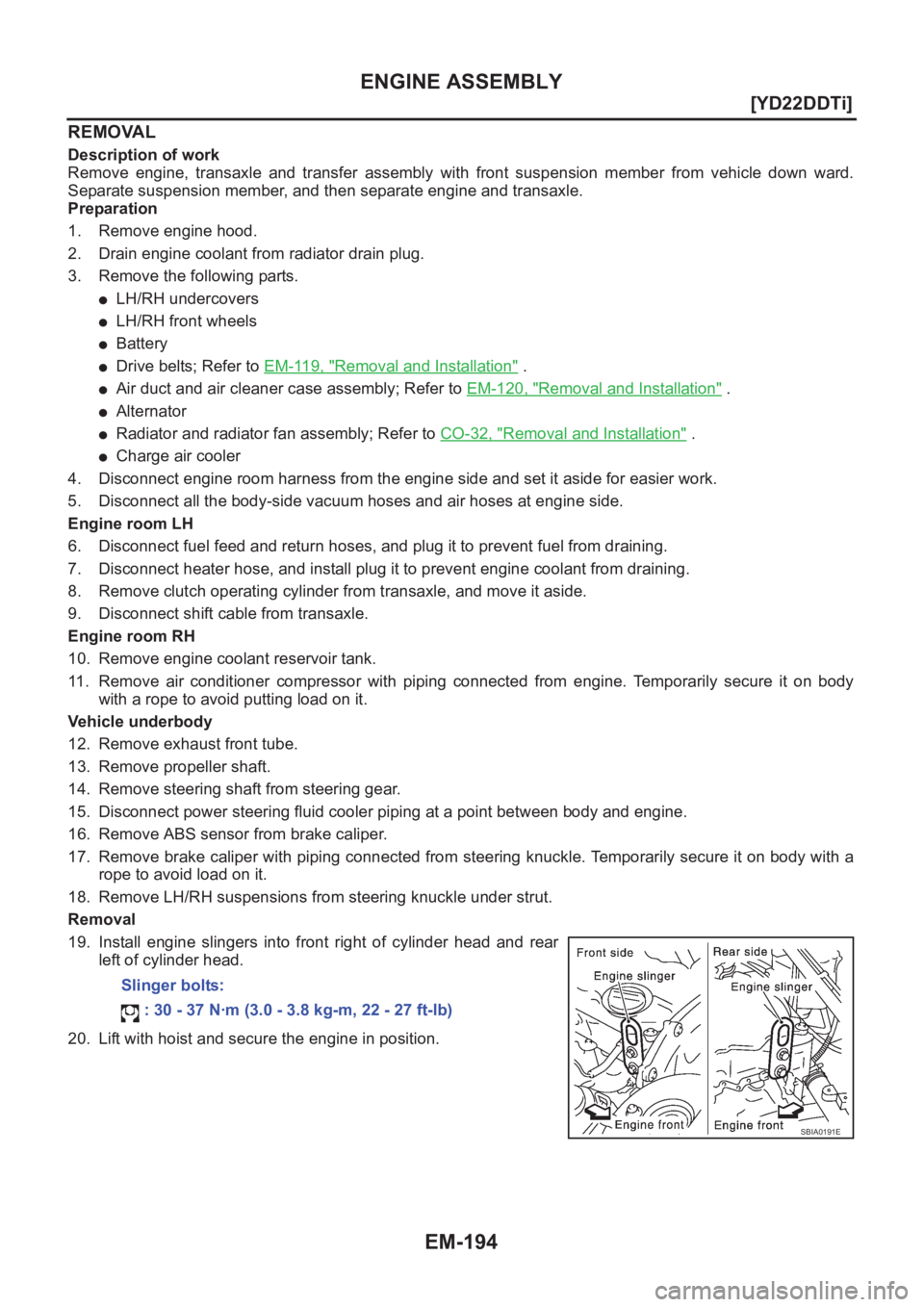
19. Install engine slingers into front right of cylinder head and rear
left of cylinder head.
20. Lift with hoist and secure the engine in position.Slinger bolts:
: 30 - 37 N·m (3.0 - 3.8 kg-m, 22 - 27 ft-lb)
SBIA0191E