Shaft NISSAN X-TRAIL 2001 Service Manual Online
[x] Cancel search | Manufacturer: NISSAN, Model Year: 2001, Model line: X-TRAIL, Model: NISSAN X-TRAIL 2001Pages: 3833, PDF Size: 39.49 MB
Page 212 of 3833
EM-162
[YD22DDTi]
CAMSHAFT
INSTALLATION
1. Install the valve lifter and adjusting shim.
●Make sure that these are installed in the same position as before the removal process.
2. Install the camshaft.
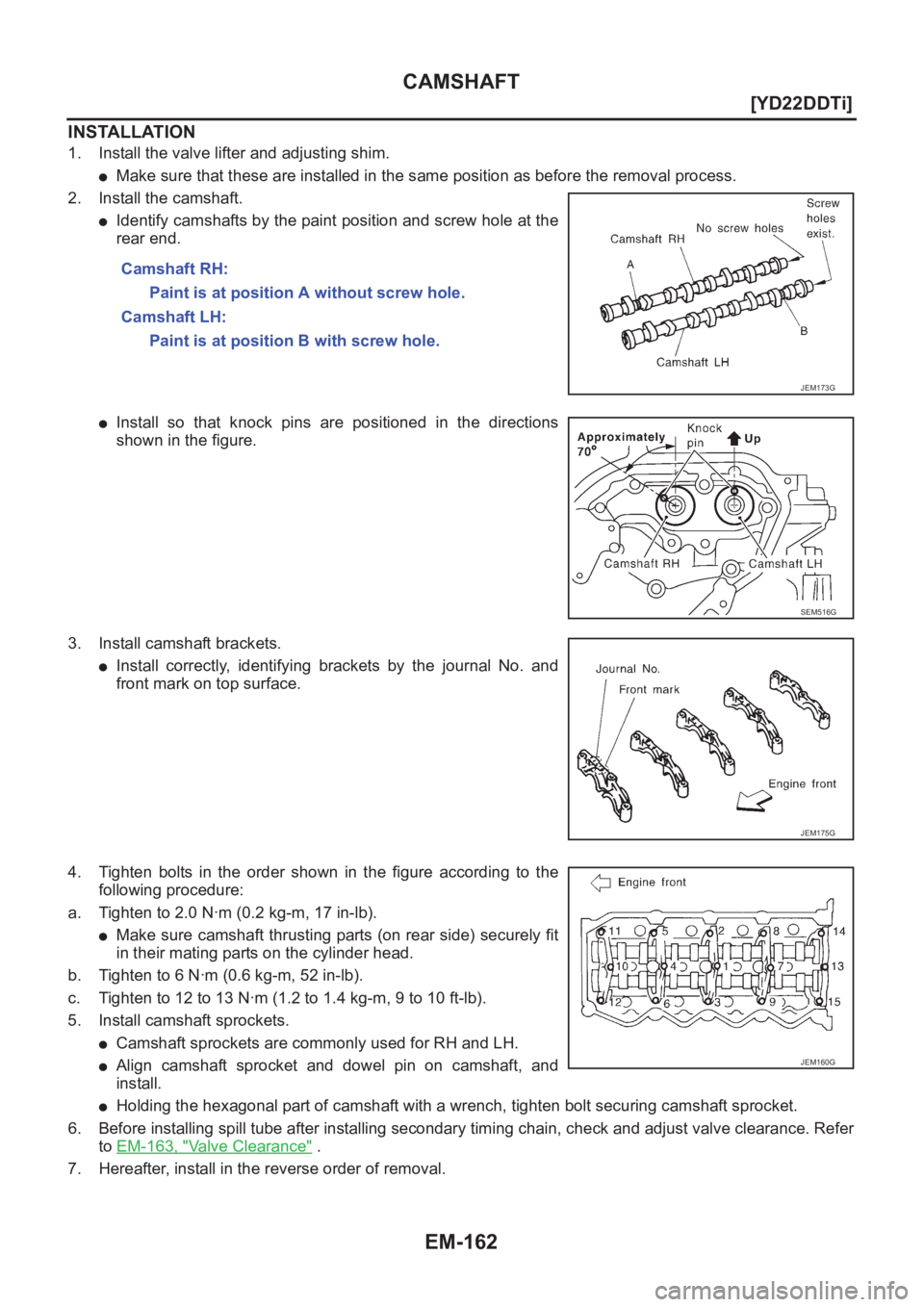
●Identify camshafts by the paint position and screw hole at the
rear end.
●Install so that knock pins are positioned in the directions
shown in the figure.
3. Install camshaft brackets.
●Install correctly, identifying brackets by the journal No. and
front mark on top surface.
4. Tighten bolts in the order shown in the figure according to the
following procedure:
a. Tighten to 2.0 N·m (0.2 kg-m, 17 in-lb).
●Make sure camshaft thrusting parts (on rear side) securely fit
in their mating parts on the cylinder head.
b. Tighten to 6 N·m (0.6 kg-m, 52 in-lb).
c. Tighten to 12 to 13 N·m (1.2 to 1.4 kg-m, 9 to 10 ft-lb).
5. Install camshaft sprockets.
●Camshaft sprockets are commonly used for RH and LH.
●Align camshaft sprocket and dowel pin on camshaft, and
install.
●Holding the hexagonal part of camshaft with a wrench, tighten bolt securing camshaft sprocket.
6. Before installing spill tube after installing secondary timing chain, check and adjust valve clearance. Refer
to EM-163, "
Valve Clearance" .
7. Hereafter, install in the reverse order of removal.Camshaft RH:
Paint is at position A without screw hole.
Camshaft LH:
Paint is at position B with screw hole.
JEM173G
SEM516G
JEM175G
JEM160G
Page 213 of 3833
CAMSHAFT
EM-163
[YD22DDTi]
C
D
E
F
G
H
I
J
K
L
MA
EM
Va l v e C l e a r a n c eEBS00LRS
INSPECTION
●When the camshaft or parts in connection with valves are
removed or replaced, and a malfunction has occurred (poor
starting, idling, or other malfunction) due to the misadjustment of
the valve clearance, inspect as follows.
●Inspect and adjust when the engine is cool (at normal tempera-
ture).
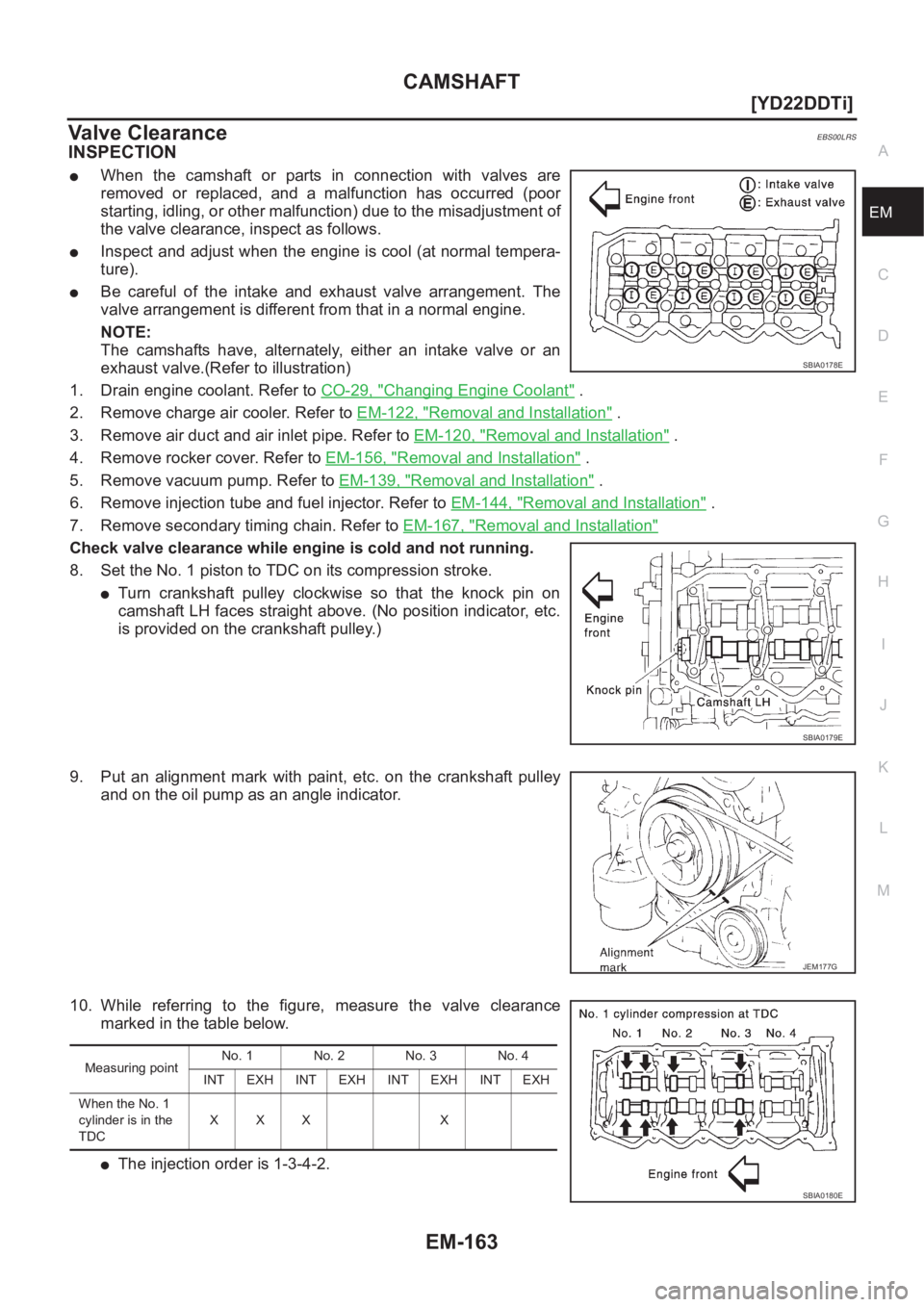
●Be careful of the intake and exhaust valve arrangement. The
valve arrangement is different from that in a normal engine.
NOTE:
The camshafts have, alternately, either an intake valve or an
exhaust valve.(Refer to illustration)
1. Drain engine coolant. Refer to CO-29, "
Changing Engine Coolant" .
2. Remove charge air cooler. Refer to EM-122, "
Removal and Installation" .
3. Remove air duct and air inlet pipe. Refer to EM-120, "
Removal and Installation" .
4. Remove rocker cover. Refer to EM-156, "
Removal and Installation" .
5. Remove vacuum pump. Refer to EM-139, "
Removal and Installation" .
6. Remove injection tube and fuel injector. Refer to EM-144, "
Removal and Installation" .
7. Remove secondary timing chain. Refer to EM-167, "
Removal and Installation"
Check valve clearance while engine is cold and not running.
8. Set the No. 1 piston to TDC on its compression stroke.
●Turn crankshaft pulley clockwise so that the knock pin on
camshaft LH faces straight above. (No position indicator, etc.
is provided on the crankshaft pulley.)
9. Put an alignment mark with paint, etc. on the crankshaft pulley
and on the oil pump as an angle indicator.
10. While referring to the figure, measure the valve clearance
marked in the table below.
●The injection order is 1-3-4-2.
SBIA0178E
SBIA0179E
JEM177G
Measuring pointNo. 1 No. 2 No. 3 No. 4
INT EXH INT EXH INT EXH INT EXH
When the No. 1
cylinder is in the
TDCXXX X
SBIA0180E
Page 214 of 3833
EM-164
[YD22DDTi]
CAMSHAFT
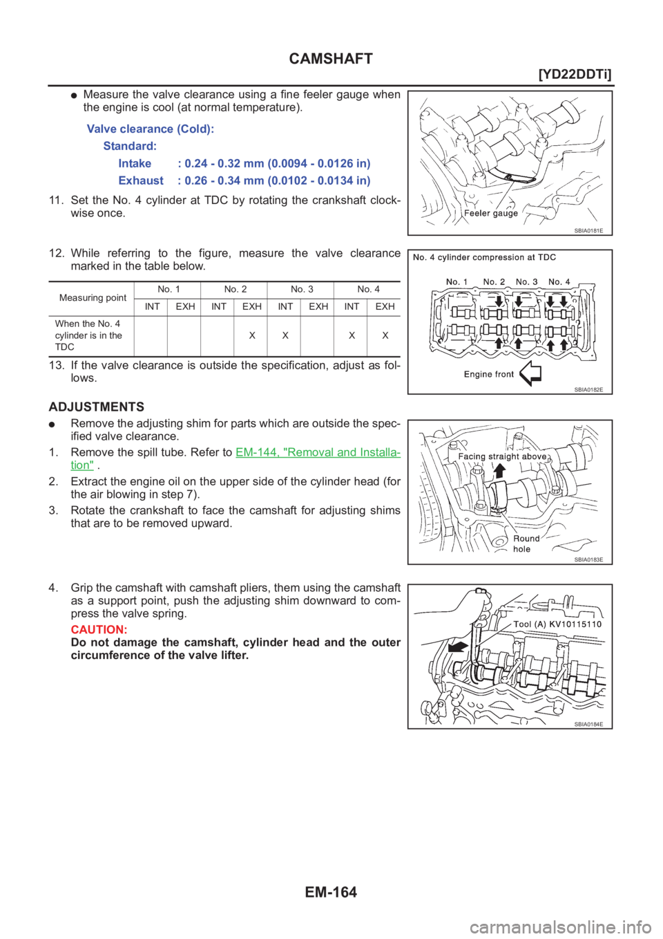
●Measure the valve clearance using a fine feeler gauge when
the engine is cool (at normal temperature).
11. Set the No. 4 cylinder at TDC by rotating the crankshaft clock-
wise once.
12. While referring to the figure, measure the valve clearance
marked in the table below.
13. If the valve clearance is outside the specification, adjust as fol-
lows.
ADJUSTMENTS
●Remove the adjusting shim for parts which are outside the spec-
ified valve clearance.
1. Remove the spill tube. Refer to EM-144, "
Removal and Installa-
tion" .
2. Extract the engine oil on the upper side of the cylinder head (for
the air blowing in step 7).
3. Rotate the crankshaft to face the camshaft for adjusting shims
that are to be removed upward.
4. Grip the camshaft with camshaft pliers, them using the camshaft
as a support point, push the adjusting shim downward to com-
press the valve spring.
CAUTION:
Do not damage the camshaft, cylinder head and the outer
circumference of the valve lifter.Valve clearance (Cold):
Standard:
Intake : 0.24 - 0.32 mm (0.0094 - 0.0126 in)
Exhaust : 0.26 - 0.34 mm (0.0102 - 0.0134 in)
SBIA0181E
Measuring pointNo. 1 No. 2 No. 3 No. 4
INT EXH INT EXH INT EXH INT EXH
When the No. 4
cylinder is in the
TDCXX XX
SBIA0182E
SBIA0183E
SBIA0184E
Page 215 of 3833
CAMSHAFT
EM-165
[YD22DDTi]
C
D
E
F
G
H
I
J
K
L
MA
EM
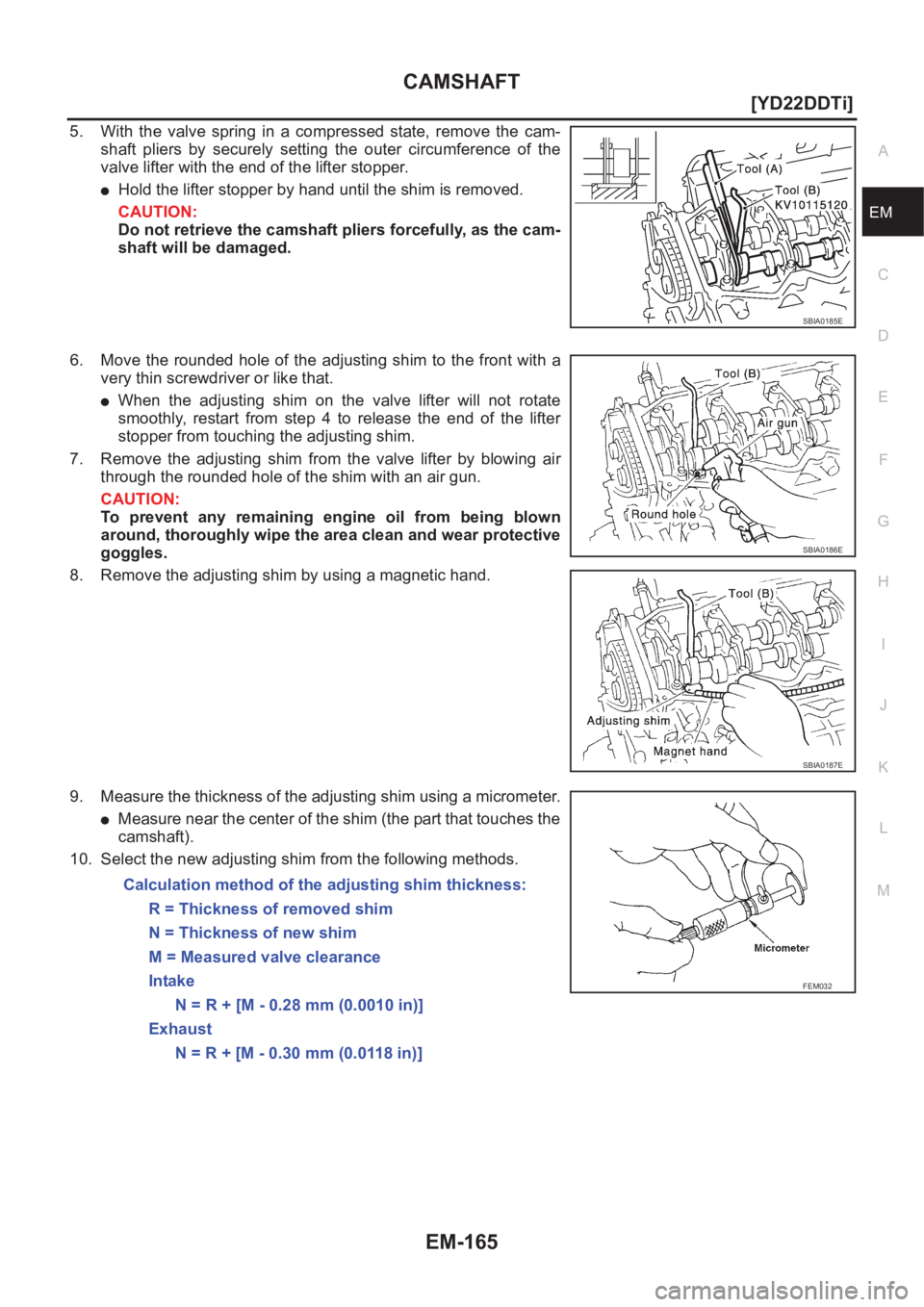
5. With the valve spring in a compressed state, remove the cam-
shaft pliers by securely setting the outer circumference of the
valve lifter with the end of the lifter stopper.
●Hold the lifter stopper by hand until the shim is removed.
CAUTION:
Do not retrieve the camshaft pliers forcefully, as the cam-
shaft will be damaged.
6. Move the rounded hole of the adjusting shim to the front with a
very thin screwdriver or like that.
●When the adjusting shim on the valve lifter will not rotate
smoothly, restart from step 4 to release the end of the lifter
stopper from touching the adjusting shim.
7. Remove the adjusting shim from the valve lifter by blowing air
through the rounded hole of the shim with an air gun.
CAUTION:
To prevent any remaining engine oil from being blown
around, thoroughly wipe the area clean and wear protective
goggles.
8. Remove the adjusting shim by using a magnetic hand.
9. Measure the thickness of the adjusting shim using a micrometer.
●Measure near the center of the shim (the part that touches the
camshaft).
10. Select the new adjusting shim from the following methods.
SBIA0185E
SBIA0186E
SBIA0187E
Calculation method of the adjusting shim thickness:
R = Thickness of removed shim
N = Thickness of new shim
M = Measured valve clearance
Intake
N = R + [M - 0.28 mm (0.0010 in)]
Exhaust
N = R + [M - 0.30 mm (0.0118 in)]
FEM032
Page 216 of 3833
EM-166
[YD22DDTi]
CAMSHAFT
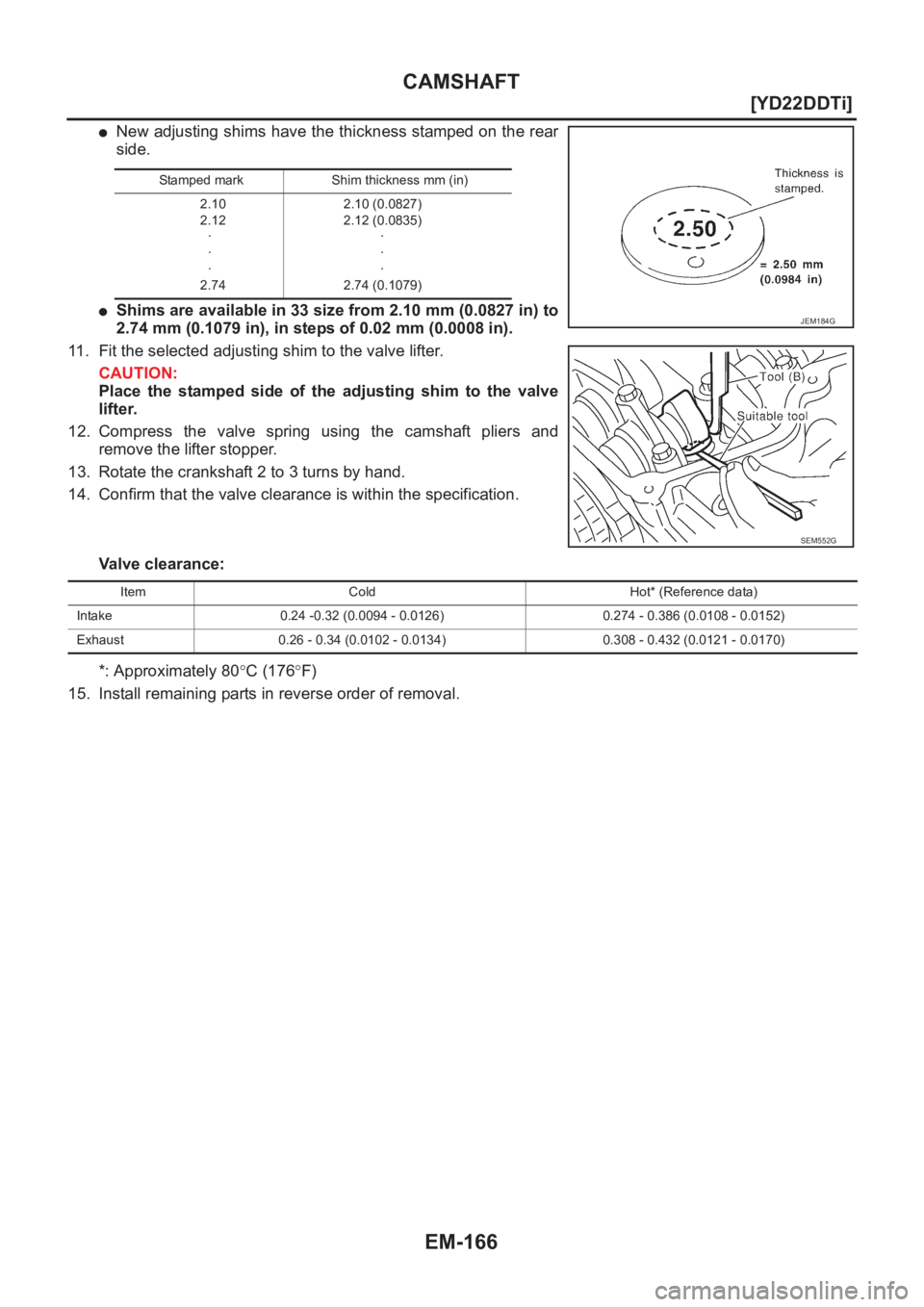
●New adjusting shims have the thickness stamped on the rear
side.
●Shims are available in 33 size from 2.10 mm (0.0827 in) to
2.74 mm (0.1079 in), in steps of 0.02 mm (0.0008 in).
11. Fit the selected adjusting shim to the valve lifter.
CAUTION:
Place the stamped side of the adjusting shim to the valve
lifter.
12. Compress the valve spring using the camshaft pliers and
remove the lifter stopper.
13. Rotate the crankshaft 2 to 3 turns by hand.
14. Confirm that the valve clearance is within the specification.
Valve clearance:
*: Approximately 80°C (176°F)
15. Install remaining parts in reverse order of removal.
Stamped mark Shim thickness mm (in)
2.10
2.12
·
·
·
2.74 2.10 (0.0827)
2.12 (0.0835)
·
·
·
2.74 (0.1079)
JEM184G
SEM552G
Item Cold Hot* (Reference data)
Intake 0.24 -0.32 (0.0094 - 0.0126) 0.274 - 0.386 (0.0108 - 0.0152)
Exhaust 0.26 - 0.34 (0.0102 - 0.0134) 0.308 - 0.432 (0.0121 - 0.0170)
Page 217 of 3833
SECONDARY TIMING CHAIN
EM-167
[YD22DDTi]
C
D
E
F
G
H
I
J
K
L
MA
EM
SECONDARY TIMING CHAINPFP:13028
Removal and InstallationEBS00LRT
CAUTION:
●After removing timing chain, do not turn crankshaft and camshaft separately, or valves will strike
piston heads.
●When installing camshafts, chain tensioners, oil seals or other sliding parts, lubricate contacting
surfaces with new engine oil.
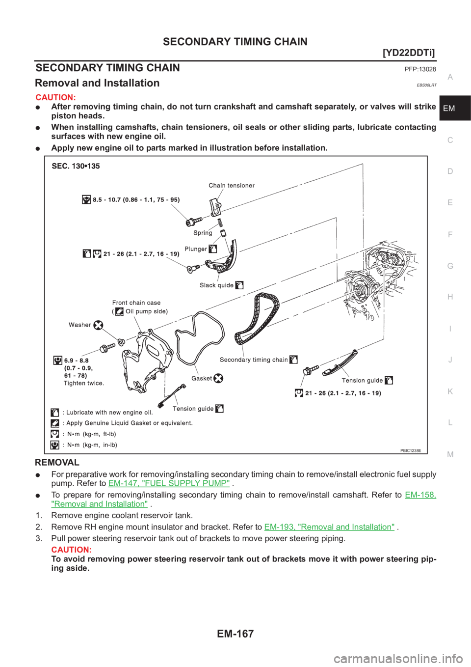
●Apply new engine oil to parts marked in illustration before installation.
REMOVAL
●For preparative work for removing/installing secondary timing chain to remove/install electronic fuel supply
pump. Refer to EM-147, "
FUEL SUPPLY PUMP" .
●To prepare for removing/installing secondary timing chain to remove/install camshaft. Refer to EM-158,
"Removal and Installation" .
1. Remove engine coolant reservoir tank.
2. Remove RH engine mount insulator and bracket. Refer to EM-193, "
Removal and Installation" .
3. Pull power steering reservoir tank out of brackets to move power steering piping.
CAUTION:
To avoid removing power steering reservoir tank out of brackets move it with power steering pip-
ing aside.
PBIC1238E
Page 218 of 3833
EM-168
[YD22DDTi]
SECONDARY TIMING CHAIN
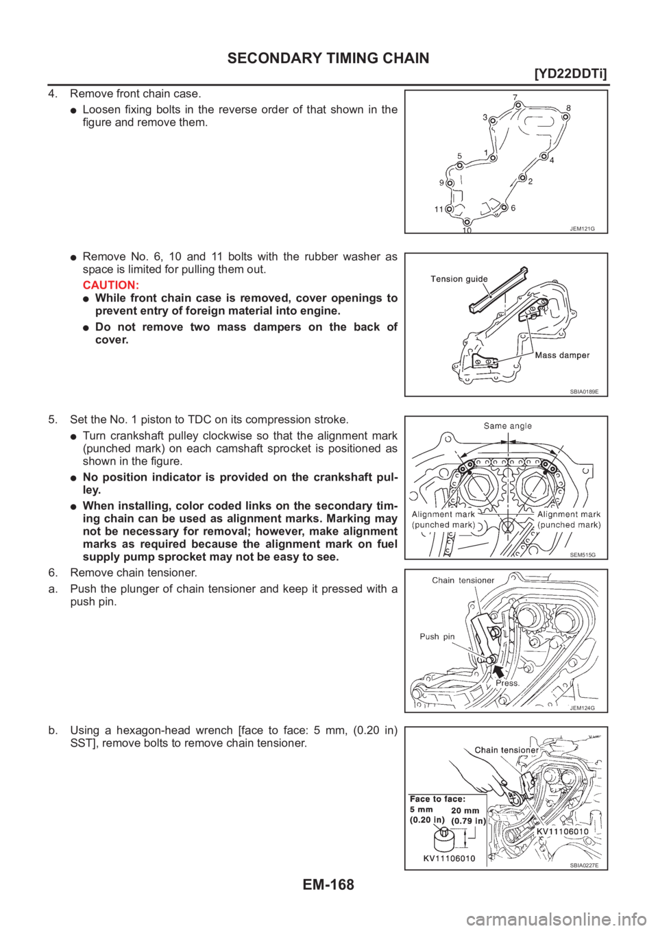
4. Remove front chain case.
●Loosen fixing bolts in the reverse order of that shown in the
figure and remove them.
●Remove No. 6, 10 and 11 bolts with the rubber washer as
space is limited for pulling them out.
CAUTION:
●While front chain case is removed, cover openings to
prevent entry of foreign material into engine.
●Do not remove two mass dampers on the back of
cover.
5. Set the No. 1 piston to TDC on its compression stroke.
●Turn crankshaft pulley clockwise so that the alignment mark
(punched mark) on each camshaft sprocket is positioned as
shown in the figure.
●No position indicator is provided on the crankshaft pul-
ley.
●When installing, color coded links on the secondary tim-
ing chain can be used as alignment marks. Marking may
not be necessary for removal; however, make alignment
marks as required because the alignment mark on fuel
supply pump sprocket may not be easy to see.
6. Remove chain tensioner.
a. Push the plunger of chain tensioner and keep it pressed with a
push pin.
b. Using a hexagon-head wrench [face to face: 5 mm, (0.20 in)
SST], remove bolts to remove chain tensioner.
JEM121G
SBIA0189E
SEM515G
JEM124G
SBIA0227E
Page 222 of 3833
EM-172
[YD22DDTi]
PRIMARY TIMING CHAIN
PRIMARY TIMING CHAIN
PFP:13028
Removal and InstallationEBS00LRU
CAUTION:
●After removing timing chain, do not turn crankshaft and camshaft separately, or valves will strike
piston heads.
●When installing camshafts, chain tensioners, oil seals or other sliding parts, lubricate contacting
surfaces with new engine oil.
●Apply new engine oil to parts marked in illustration before installation.
Page 223 of 3833
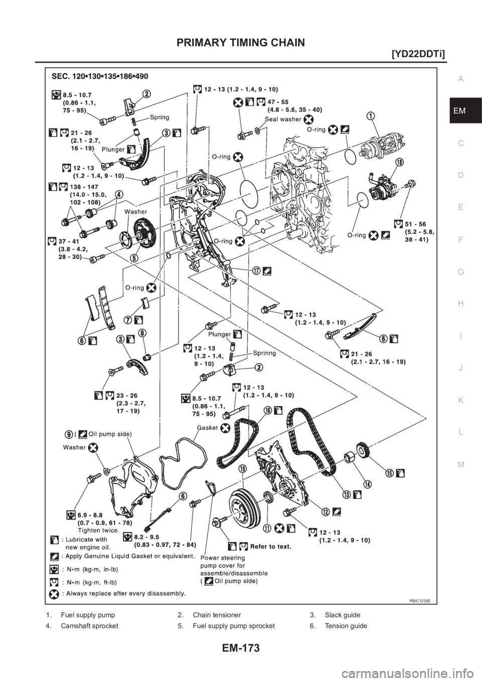
PRIMARY TIMING CHAIN
EM-173
[YD22DDTi]
C
D
E
F
G
H
I
J
K
L
MA
EM
PBIC1230E
1. Fuel supply pump 2. Chain tensioner 3. Slack guide
4. Camshaft sprocket 5. Fuel supply pump sprocket 6. Tension guide
Page 224 of 3833
EM-174
[YD22DDTi]
PRIMARY TIMING CHAIN
REMOVAL
1. Remove engine coolant reservoir tank.
2. Remove charge air cooler and bracket. Refer to EM-122, "
Removal and Installation" .
3. Remove air cleaner and air duct. Refer to EM-120, "
Removal and Installation" .
4. Remove rocker cover. Refer to EM-156, "
Removal and Installation" .
5. Remove RH engine mount insulator and bracket. Refer to EM-193, "
Removal and Installation" .
6. Pull power steering reservoir tank out of brackets to move power steering piping.
CAUTION:
To avoid removing power steering reservoir tank out of brackets move it with power steering pip-
ing aside.
7. Remove oil pan. Refer to EM-133, "
Removal and Installation" .
8. Remove oil filter bracket. Refer to LU-22, "
OIL FILTER BRACKET" .
9. Remove injection tube and fuel injector. Refer to EM-144, "
Removal and Installation" .
10. Remove secondary timing chain and associated parts. Refer to EM-167, "
Removal and Installation" .
11. When removing rear chain case, remove camshaft sprockets. Refer to EM-158, "
Removal and Installa-
tion" .
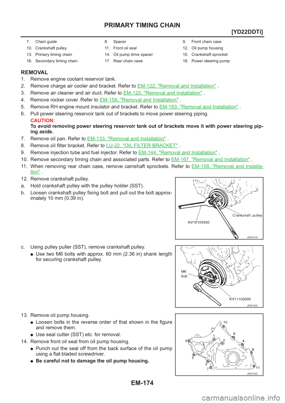
12. Remove crankshaft pulley.
a. Hold crankshaft pulley with the pulley holder (SST).
b. Loosen crankshaft pulley fixing bolt and pull out the bolt approx-
imately 10 mm (0.39 in).
c. Using pulley puller (SST), remove crankshaft pulley.
●Use two M6 bolts with approx. 60 mm (2.36 in) shank length
for securing crankshaft pulley.
13. Remove oil pump housing.
●Loosen bolts in the reverse order of that shown in the figure
and remove them.
●Use seal cutter (SST) etc. for removal.
14. Remove front oil seal from oil pump housing.
●Punch out the seal off from the back surface of the oil pump
using a flat-bladed screwdriver.
●Be careful not to damage the oil pump housing.
7. Chain guide 8. Spacer 9. Front chain case
10. Crankshaft pulley 11. Front oil seal 12. Oil pump housing
13. Primary timing chain 14. Oil pump drive spacer 15. Crankshaft sprocket
16. Secondary timing chain 17. Rear chain case 18. Power steering pump
JEM131G
JEM132G
JEM133G