ECO mode NISSAN X-TRAIL 2001 Service User Guide
[x] Cancel search | Manufacturer: NISSAN, Model Year: 2001, Model line: X-TRAIL, Model: NISSAN X-TRAIL 2001Pages: 3833, PDF Size: 39.49 MB
Page 391 of 3833
BASIC SERVICE PROCEDURE
EC-41
[QR25(WITH EURO-OBD)]
C
D
E
F
G
H
I
J
K
L
MA
EC
Without CONSULT-II
NOTE:
●It is better to count the time accurately with a clock.
●It is impossible to switch the diagnostic mode when an accelerator pedal position sensor circuit
has a malfunction.
1. Perform EC-39, "
Accelerator Pedal Released Position Learning" .
2. Perform EC-39, "
Throttle Valve Closed Position Learning" .
3. Start engine and warm it up to normal operating temperature.
4. Check that all items listed under the topic “PREPARATION” (previously mentioned) are in good order.
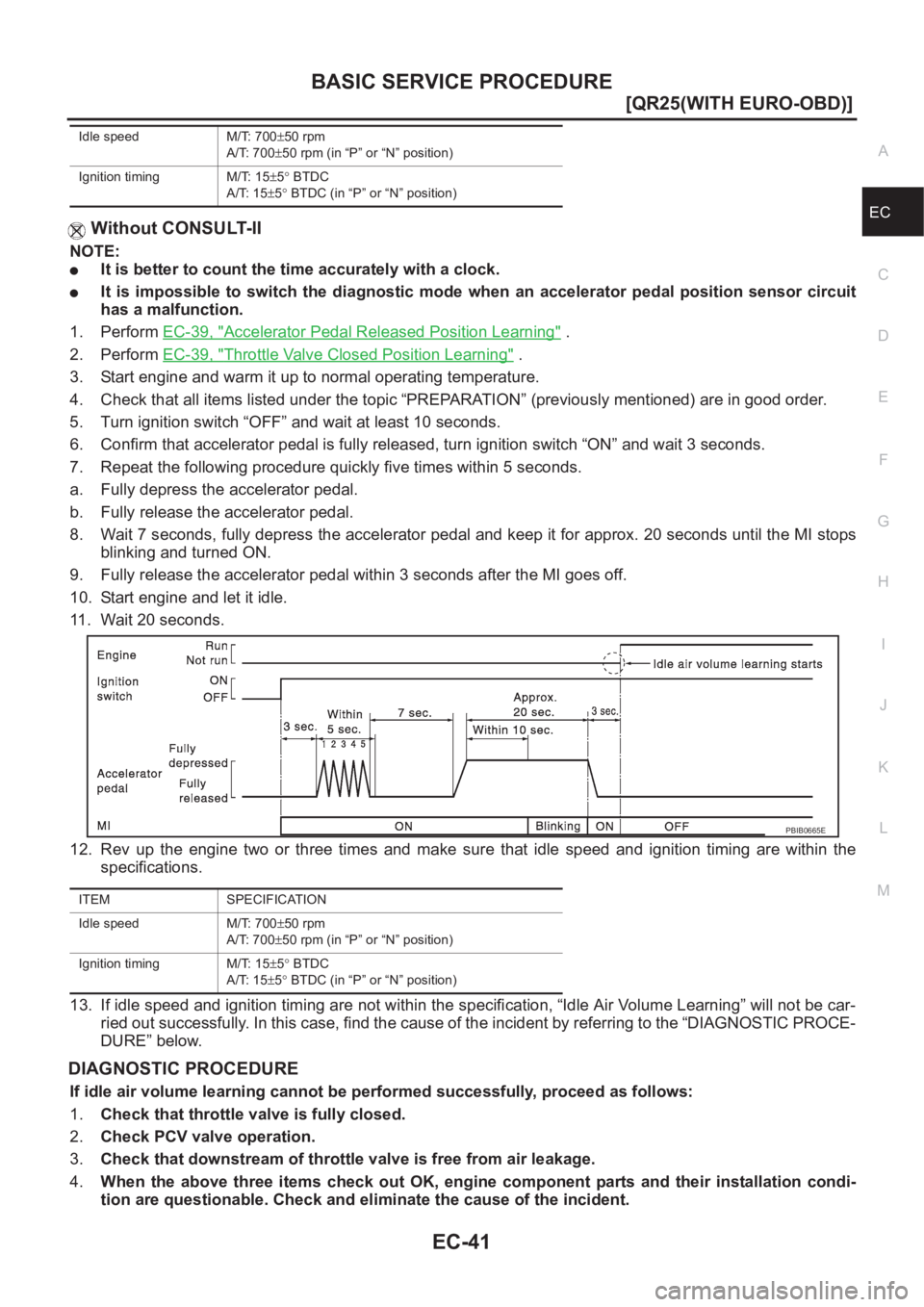
5. Turn ignition switch “OFF” and wait at least 10 seconds.
6. Confirm that accelerator pedal is fully released, turn ignition switch “ON” and wait 3 seconds.
7. Repeat the following procedure quickly five times within 5 seconds.
a. Fully depress the accelerator pedal.
b. Fully release the accelerator pedal.
8. Wait 7 seconds, fully depress the accelerator pedal and keep it for approx. 20 seconds until the MI stops
blinking and turned ON.
9. Fully release the accelerator pedal within 3 seconds after the MI goes off.
10. Start engine and let it idle.
11. Wait 20 seconds.
12. Rev up the engine two or three times and make sure that idle speed and ignition timing are within the
specifications.
13. If idle speed and ignition timing are not within the specification, “Idle Air Volume Learning” will not be car-
ried out successfully. In this case, find the cause of the incident by referring to the “DIAGNOSTIC PROCE-
DURE” below.
DIAGNOSTIC PROCEDURE
If idle air volume learning cannot be performed successfully, proceed as follows:
1.Check that throttle valve is fully closed.
2.Check PCV valve operation.
3.Check that downstream of throttle valve is free from air leakage.
4.When the above three items check out OK, engine component parts and their installation condi-
tion are questionable. Check and eliminate the cause of the incident.
Idle speed M/T: 700±50 rpm
A/T: 700±50 rpm (in “P” or “N” position)
Ignition timing M/T: 15±5° BTDC
A/T: 15±5° BTDC (in “P” or “N” position)
ITEM SPECIFICATION
Idle speed M/T: 700±50 rpm
A/T: 700±50 rpm (in “P” or “N” position)
Ignition timing M/T: 15±5° BTDC
A/T: 15±5° BTDC (in “P” or “N” position)
PBIB0665E
Page 394 of 3833
EC-44
[QR25(WITH EURO-OBD)]
ON BOARD DIAGNOSTIC (OBD) SYSTEM
ON BOARD DIAGNOSTIC (OBD) SYSTEM
PFP:00028
IntroductionEBS00M0M
The ECM has an on board diagnostic system, which detects malfunctions related to engine sensors or actua-
tors. The ECM also records various emission-related diagnostic information including:
The above information can be checked using procedures listed in the table below.
×: Applicable —: Not applicable
*1: 1st trip DTCs for self-diagnoses concerning SRT items cannot be shown on the GST display.
*2: When DTC and 1st trip DTC simultaneously appear on the display, they cannot be clearly distinguished from each other.
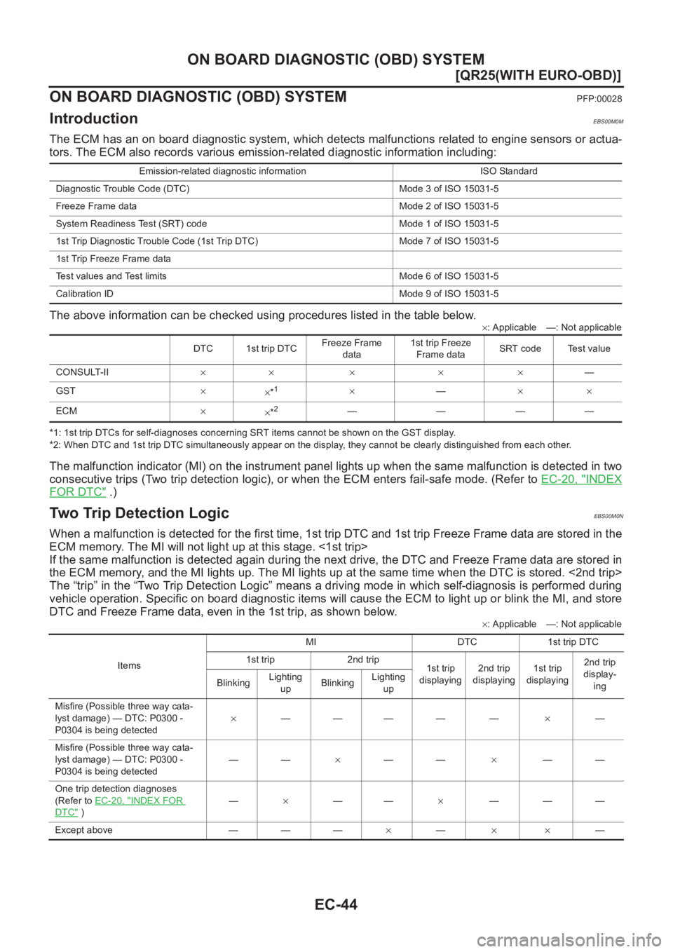
The malfunction indicator (MI) on the instrument panel lights up when the same malfunction is detected in two
consecutive trips (Two trip detection logic), or when the ECM enters fail-safe mode. (Refer to EC-20, "
INDEX
FOR DTC" .)
Two Trip Detection LogicEBS00M0N
When a malfunction is detected for the first time, 1st trip DTC and 1st trip Freeze Frame data are stored in the
ECM memory. The MI will not light up at this stage. <1st trip>
If the same malfunction is detected again during the next drive, the DTC and Freeze Frame data are stored in
the ECM memory, and the MI lights up. The MI lights up at the same time when the DTC is stored. <2nd trip>
The “trip” in the “Two Trip Detection Logic” means a driving mode in which self-diagnosis is performed during
vehicle operation. Specific on board diagnostic items will cause the ECM to light up or blink the MI, and store
DTC and Freeze Frame data, even in the 1st trip, as shown below.
×: Applicable —: Not applicable Emission-related diagnostic information ISO Standard
Diagnostic Trouble Code (DTC) Mode 3 of ISO 15031-5
Freeze Frame data Mode 2 of ISO 15031-5
System Readiness Test (SRT) code Mode 1 of ISO 15031-5
1st Trip Diagnostic Trouble Code (1st Trip DTC) Mode 7 of ISO 15031-5
1st Trip Freeze Frame data
Test values and Test limits Mode 6 of ISO 15031-5
Calibration ID Mode 9 of ISO 15031-5
DTC 1st trip DTCFreeze Frame
data1st trip Freeze
Frame dataSRT code Test value
CONSULT-II×× × × ×—
GST×
×*
1×—××
ECM×
×*
2————
ItemsMI DTC 1st trip DTC
1st trip 2nd trip
1st trip
displaying2nd trip
displaying1st trip
displaying2nd trip
display-
ing BlinkingLighting
upBlinkingLighting
up
Misfire (Possible three way cata-
lyst damage) — DTC: P0300 -
P0304 is being detected×———— —×—
Misfire (Possible three way cata-
lyst damage) — DTC: P0300 -
P0304 is being detected——×——×——
One trip detection diagnoses
(Refer to EC-20, "
INDEX FOR
DTC" )—×——×———
Except above — — —×—××—
Page 397 of 3833
ON BOARD DIAGNOSTIC (OBD) SYSTEM
EC-47
[QR25(WITH EURO-OBD)]
C
D
E
F
G
H
I
J
K
L
MA
EC
*2: These numbers are prescribed by ISO 15031-5.
*3: In Diagnostic Test Mode II (Self-diagnostic results), these numbers are controlled by NISSAN.
*4: These are not displayed with GST.
*5: For A/T models.
*6: The trouble shooting for this DTC needs CONSULT-II.
*7: When the fail-safe operations for both self-diagnoses occur at the same time, the MI illuminates.
DTC AND 1ST TRIP DTC
The 1st trip DTC (whose number is the same as the DTC number) is displayed for the latest self-diagnostic
result obtained. If the ECM memory was cleared previously, and the 1st trip DTC did not reoccur, the 1st trip
DTC will not be displayed.
If a malfunction is detected during the 1st trip, the 1st trip DTC is stored in the ECM memory. The MI will not
light up (two trip detection logic). If the same malfunction is not detected in the 2nd trip (meeting the required
driving pattern), the 1st trip DTC is cleared from the ECM memory. If the same malfunction is detected in the
2nd trip, both the 1st trip DTC and DTC are stored in the ECM memory and the MI lights up. In other words,
the DTC is stored in the ECM memory and the MI lights up when the same malfunction occurs in two consec-
utive trips. If a 1st trip DTC is stored and a non-diagnostic operation is performed between the 1st and 2nd
trips, only the 1st trip DTC will continue to be stored. For malfunctions that blink or light up the MI during the
1st trip, the DTC and 1st trip DTC are stored in the ECM memory.
Procedures for clearing the DTC and the 1st trip DTC from the ECM memory are described in EC-56, "
HOW
TO ERASE EMISSION-RELATED DIAGNOSTIC INFORMATION" .
For malfunctions in which 1st trip DTCs are displayed, refer to EC-45
. These items are required by legal reg-
ulations to continuously monitor the system/component. In addition, the items monitored non-continuously are
also displayed on CONSULT-II.
1st trip DTC is specified in Mode 7 of ISO 15031-5. 1st trip DTC detection occurs without lighting up the MI
and therefore does not warn the driver of a an incident. However, 1st trip DTC detection will not prevent the
vehicle from being tested, for example during Inspection/Maintenance (I/M) tests.
When a 1st trip DTC is detected, check, print out or write down and erase (1st trip) DTC and Freeze Frame
data as specified in “Work Flow” procedure Step II, refer to EC-68
. Then perform “DTC Confirmation Proce-
dure” or “Overall Function Check” to try to duplicate the malfunction. If the malfunction is duplicated, the item
requires repair.
How to Read DTC and 1st Trip DTC
DTC and 1st trip DTC can be read by the following methods.
With CONSULT-II
With GST
CONSULT-II or GST (Generic Scan Tool) Examples: P0340, P0705, P0750, etc.
These DTCs are prescribed by ISO 15031-5.
(CONSULT-II also displays the malfunctioning component or system.)
No Tools
The number of blinks of the MI in the Diagnostic Test Mode II (Self-Diagnostic Results) indicates the DTC.
Example: 0102, 0340 etc.
These DTCs are controlled by NISSAN.
●1st trip DTC No. is the same as DTC No.
●Output of a DTC indicates a malfunction. However, GST or the Diagnostic Test Mode II do not indi-
cate whether the malfunction is still occurring or has occurred in the past and has returned to nor-
mal. CONSULT-II can identify malfunction status as shown below. Therefore, using CONSULT-II (if
available) is recommended.
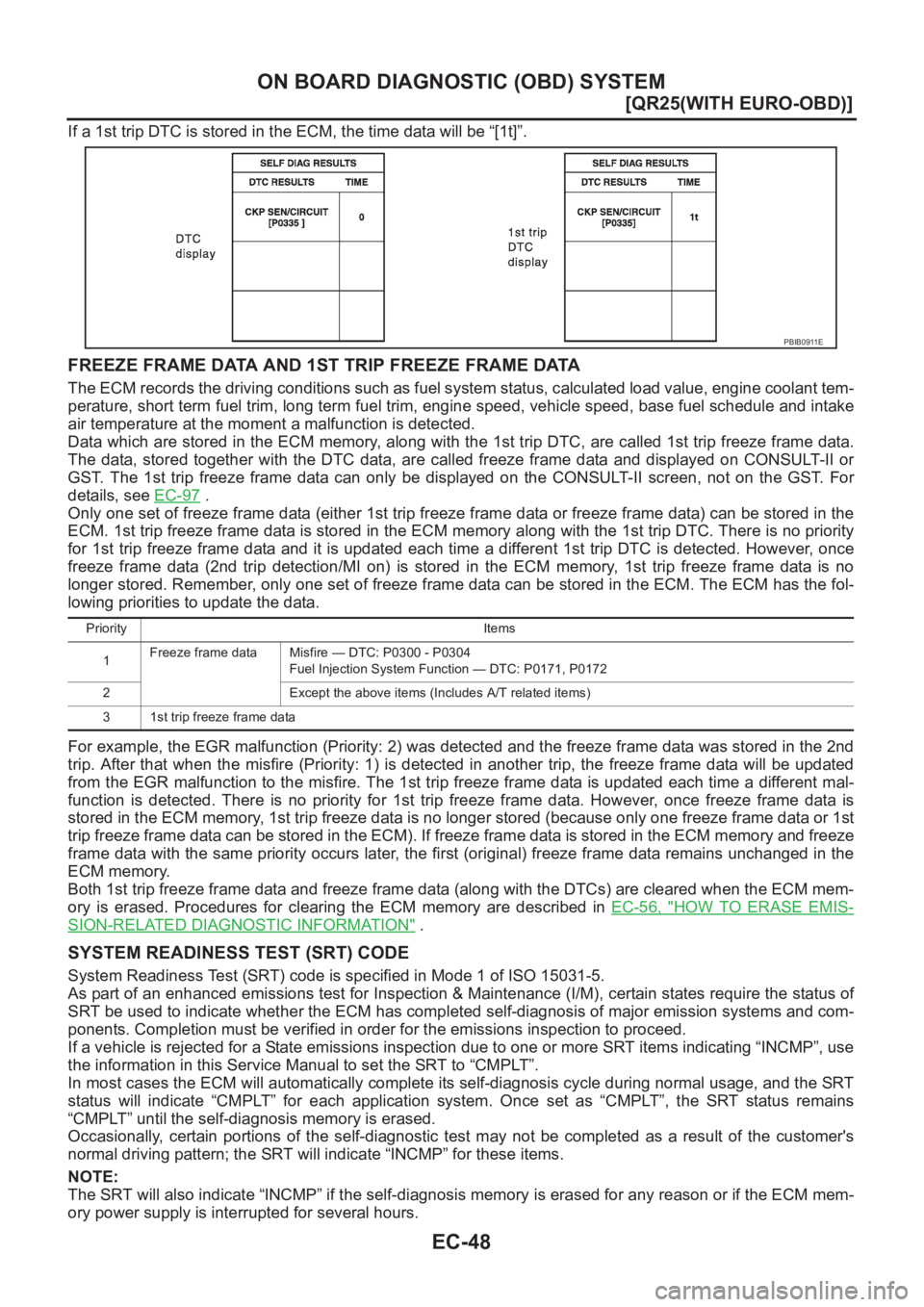
A sample of CONSULT-II display for DTC and 1st trip DTC is shown below. DTC or 1st trip DTC of a malfunc-
tion is displayed in SELF-DIAGNOSTIC RESULTS mode of CONSULT-II. Time data indicates how many times
the vehicle was driven after the last detection of a DTC.
If the DTC is being detected currently, the time data will be “0”.
Page 398 of 3833
EC-48
[QR25(WITH EURO-OBD)]
ON BOARD DIAGNOSTIC (OBD) SYSTEM
If a 1st trip DTC is stored in the ECM, the time data will be “[1t]”.
FREEZE FRAME DATA AND 1ST TRIP FREEZE FRAME DATA
The ECM records the driving conditions such as fuel system status, calculated load value, engine coolant tem-
perature, short term fuel trim, long term fuel trim, engine speed, vehicle speed, base fuel schedule and intake
air temperature at the moment a malfunction is detected.
Data which are stored in the ECM memory, along with the 1st trip DTC, are called 1st trip freeze frame data.
The data, stored together with the DTC data, are called freeze frame data and displayed on CONSULT-II or
GST. The 1st trip freeze frame data can only be displayed on the CONSULT-II screen, not on the GST. For
details, see EC-97
.
Only one set of freeze frame data (either 1st trip freeze frame data or freeze frame data) can be stored in the
ECM. 1st trip freeze frame data is stored in the ECM memory along with the 1st trip DTC. There is no priority
for 1st trip freeze frame data and it is updated each time a different 1st trip DTC is detected. However, once
freeze frame data (2nd trip detection/MI on) is stored in the ECM memory, 1st trip freeze frame data is no
longer stored. Remember, only one set of freeze frame data can be stored in the ECM. The ECM has the fol-
lowing priorities to update the data.
For example, the EGR malfunction (Priority: 2) was detected and the freeze frame data was stored in the 2nd
trip. After that when the misfire (Priority: 1) is detected in another trip, the freeze frame data will be updated
from the EGR malfunction to the misfire. The 1st trip freeze frame data is updated each time a different mal-
function is detected. There is no priority for 1st trip freeze frame data. However, once freeze frame data is
stored in the ECM memory, 1st trip freeze data is no longer stored (because only one freeze frame data or 1st
trip freeze frame data can be stored in the ECM). If freeze frame data is stored in the ECM memory and freeze
frame data with the same priority occurs later, the first (original) freeze frame data remains unchanged in the
ECM memory.
Both 1st trip freeze frame data and freeze frame data (along with the DTCs) are cleared when the ECM mem-
ory is erased. Procedures for clearing the ECM memory are described in EC-56, "
HOW TO ERASE EMIS-
SION-RELATED DIAGNOSTIC INFORMATION" .
SYSTEM READINESS TEST (SRT) CODE
System Readiness Test (SRT) code is specified in Mode 1 of ISO 15031-5.
As part of an enhanced emissions test for Inspection & Maintenance (I/M), certain states require the status of
SRT be used to indicate whether the ECM has completed self-diagnosis of major emission systems and com-
ponents. Completion must be verified in order for the emissions inspection to proceed.
If a vehicle is rejected for a State emissions inspection due to one or more SRT items indicating “INCMP”, use
the information in this Service Manual to set the SRT to “CMPLT”.
In most cases the ECM will automatically complete its self-diagnosis cycle during normal usage, and the SRT
status will indicate “CMPLT” for each application system. Once set as “CMPLT”, the SRT status remains
“CMPLT” until the self-diagnosis memory is erased.
Occasionally, certain portions of the self-diagnostic test may not be completed as a result of the customer's
normal driving pattern; the SRT will indicate “INCMP” for these items.
NOTE:
The SRT will also indicate “INCMP” if the self-diagnosis memory is erased for any reason or if the ECM mem-
ory power supply is interrupted for several hours.
PBIB0911E
Priority Items
1Freeze frame data Misfire — DTC: P0300 - P0304
Fuel Injection System Function — DTC: P0171, P0172
2 Except the above items (Includes A/T related items)
3 1st trip freeze frame data
Page 405 of 3833
ON BOARD DIAGNOSTIC (OBD) SYSTEM
EC-55
[QR25(WITH EURO-OBD)]
C
D
E
F
G
H
I
J
K
L
MA
EC
●The time required for each diagnosis varies with road surface conditions, weather, altitude, individual driv-
ing habits, etc.
Zone A refers to the range where the time, required for the diagnosis under normal conditions*, is the
shortest.
Zone B refers to the range where the diagnosis can still be performed if the diagnosis is not completed
within zone A.
*: Normal conditions refer to the following:
●Sea level
●Flat road
●Ambient air temperature: 20 - 30°C (68 - 86°F)
●Diagnosis is performed as quickly as possible under normal conditions.
Under different conditions [For example: ambient air temperature other than 20 - 30°C (68 - 86°F)], diag-
nosis may also be performed.
Pattern 1:
●The engine is started at the engine coolant temperature of −10 to 35°C (14 to 95°F)
(where the voltage between the ECM terminal 93 and ground is 3.0 - 4.3V).
●The engine must be operated at idle speed until the engine coolant temperature is greater than
70°C (158°F) (where the voltage between the ECM terminal 93 and ground is lower than 1.4V).
Pattern 2:
●When steady-state driving is performed again even after it is interrupted, each diagnosis can be con-
ducted. In this case, the time required for diagnosis may be extended.
Pattern 3:
●The driving pattern outlined in *2 must be repeated at least 3 times.
Pattern 4:
●Tests are performed after the engine has been operated for at least 17 minutes.
●The accelerator pedal must be held very steady during steady-state driving.
●If the accelerator pedal is moved, the test must be conducted all over again.
*1: Depress the accelerator pedal until vehicle speed is 90 km/h (56 MPH), then release the accelerator pedal
and keep it released for more than 10 seconds. Depress the accelerator pedal until vehicle speed is 90 km/h
(56 MPH) again.
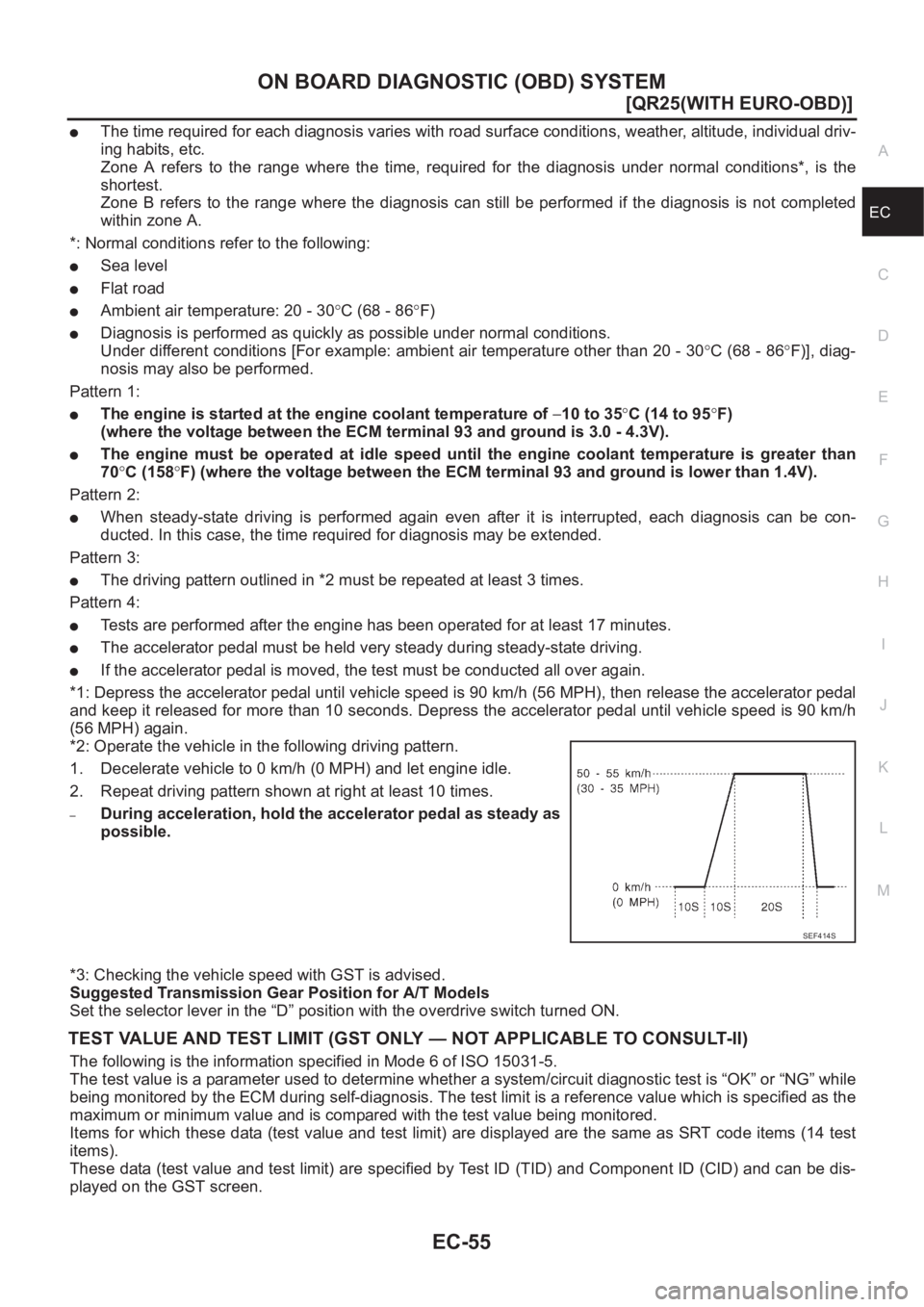
*2: Operate the vehicle in the following driving pattern.
1. Decelerate vehicle to 0 km/h (0 MPH) and let engine idle.
2. Repeat driving pattern shown at right at least 10 times.
–During acceleration, hold the accelerator pedal as steady as
possible.
*3: Checking the vehicle speed with GST is advised.
Suggested Transmission Gear Position for A/T Models
Set the selector lever in the “D” position with the overdrive switch turned ON.
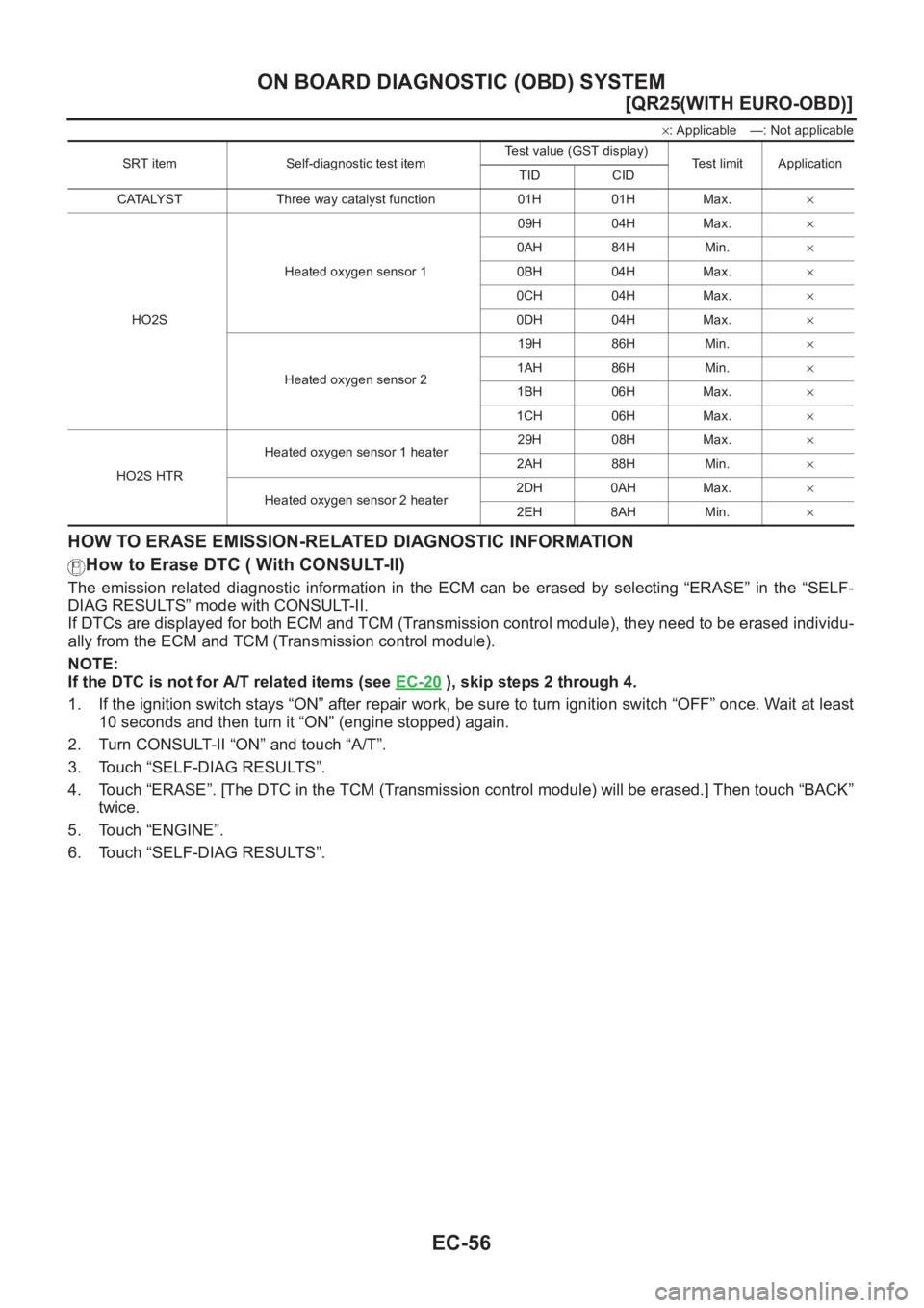
TEST VALUE AND TEST LIMIT (GST ONLY — NOT APPLICABLE TO CONSULT-II)
The following is the information specified in Mode 6 of ISO 15031-5.
The test value is a parameter used to determine whether a system/circuit diagnostic test is “OK” or “NG” while
being monitored by the ECM during self-diagnosis. The test limit is a reference value which is specified as the
maximum or minimum value and is compared with the test value being monitored.
Items for which these data (test value and test limit) are displayed are the same as SRT code items (14 test
items).
These data (test value and test limit) are specified by Test ID (TID) and Component ID (CID) and can be dis-
played on the GST screen.
SEF414S
Page 406 of 3833
EC-56
[QR25(WITH EURO-OBD)]
ON BOARD DIAGNOSTIC (OBD) SYSTEM
×: Applicable —: Not applicable
HOW TO ERASE EMISSION-RELATED DIAGNOSTIC INFORMATION
How to Erase DTC ( With CONSULT-II)
The emission related diagnostic information in the ECM can be erased by selecting “ERASE” in the “SELF-
DIAG RESULTS” mode with CONSULT-II.
If DTCs are displayed for both ECM and TCM (Transmission control module), they need to be erased individu-
ally from the ECM and TCM (Transmission control module).
NOTE:
If the DTC is not for A/T related items (see EC-20
), skip steps 2 through 4.
1. If the ignition switch stays “ON” after repair work, be sure to turn ignition switch “OFF” once. Wait at least
10 seconds and then turn it “ON” (engine stopped) again.
2. Turn CONSULT-II “ON” and touch “A/T”.
3. Touch “SELF-DIAG RESULTS”.
4. Touch “ERASE”. [The DTC in the TCM (Transmission control module) will be erased.] Then touch “BACK”
twice.
5. Touch “ENGINE”.
6. Touch “SELF-DIAG RESULTS”.
SRT item Self-diagnostic test itemTest value (GST display)
Test limit Application
TID CID
CATALYST Three way catalyst function 01H 01H Max.×
HO2SHeated oxygen sensor 109H 04H Max.×
0AH 84H Min.×
0BH 04H Max.×
0CH 04H Max.×
0DH 04H Max.×
Heated oxygen sensor 219H 86H Min.×
1AH 86H Min.×
1BH 06H Max.×
1CH 06H Max.×
HO2S HTRHeated oxygen sensor 1 heater29H 08H Max.×
2AH 88H Min.×
Heated oxygen sensor 2 heater2DH 0AH Max.×
2EH 8AH Min.×
Page 407 of 3833

ON BOARD DIAGNOSTIC (OBD) SYSTEM
EC-57
[QR25(WITH EURO-OBD)]
C
D
E
F
G
H
I
J
K
L
MA
EC
7. Touch “ERASE”. (The DTC in the ECM will be erased.)
How to Erase DTC ( With GST)
The emission related diagnostic information in the ECM can be erased by selecting Mode 4 with GST.
NOTE:
If the DTC is not for A/T related items (see EC-20
), skip step 2.
1. If the ignition switch stays “ON” after repair work, be sure to turn ignition switch “OFF” once. Wait at least
10 seconds and then turn it “ON” (engine stopped) again.
2. Perform “SELF-DIAGNOSTIC PROCEDURE (Without CONSULT-II)” in AT section titled “TROUBLE
DIAGNOSIS”, “Self-diagnosis”. (The engine warm-up step can be skipped when performing the diagnosis
only to erase the DTC.)
3. Select Mode 4 with GST (Generic Scan Tool).
How to Erase DTC ( No Tools)
1. If the ignition switch stays “ON” after repair work, be sure to turn ignition switch “OFF” once.
2. Wait at least 10 seconds and then turn it “ON” (engine stopped) again.
3. Change the diagnostic test mode from Mode II to Mode I by depressing the accelerator pedal. Refer to
EC-59, "
HOW TO SWITCH DIAGNOSTIC TEST MODE" .
●If the battery is disconnected, the emission-related diagnostic information will be lost after
approx. 24 hours.
●The following data are cleared when the ECM memory is erased.
1. Diagnostic trouble codes
2. 1st trip diagnostic trouble codes
3. Freeze frame data
4. 1st trip freeze frame data
SEF966X
Page 409 of 3833
ON BOARD DIAGNOSTIC (OBD) SYSTEM
EC-59
[QR25(WITH EURO-OBD)]
C
D
E
F
G
H
I
J
K
L
MA
EC
MI Flashing without DTC
If the ECM is in Diagnostic Test Mode II, MI may flash when engine is running. In this case, check ECM diag-
nostic test mode. EC-59, "
HOW TO SWITCH DIAGNOSTIC TEST MODE" .
How to switch the diagnostic test (function) modes, and details of the above functions are described later, EC-
59 .
The following emission-related diagnostic information is cleared when the ECM memory is erased.
1. Diagnostic trouble codes
2. 1st trip diagnostic trouble codes
3. Freeze frame data
4. 1st trip freeze frame data
5. System readiness test (SRT) codes
6. Test values
7. Others
HOW TO SWITCH DIAGNOSTIC TEST MODE
NOTE:
●It is better to count the time accurately with a clock.
●It is impossible to switch the diagnostic mode when an accelerator pedal position sensor circuit
has a malfunction.
●Always ECM returns to Diagnostic Test Mode I after ignition switch is turned “OFF”.
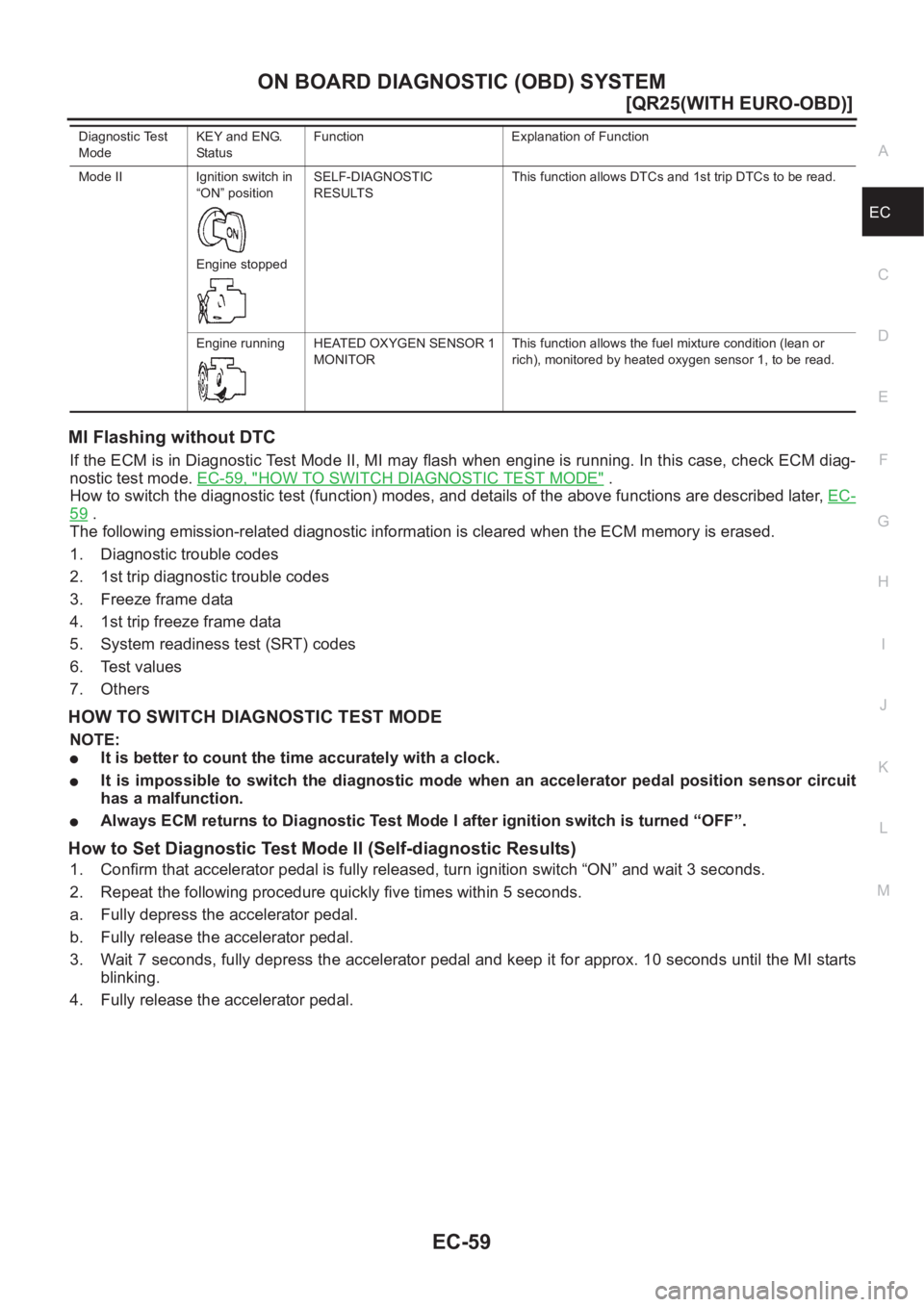
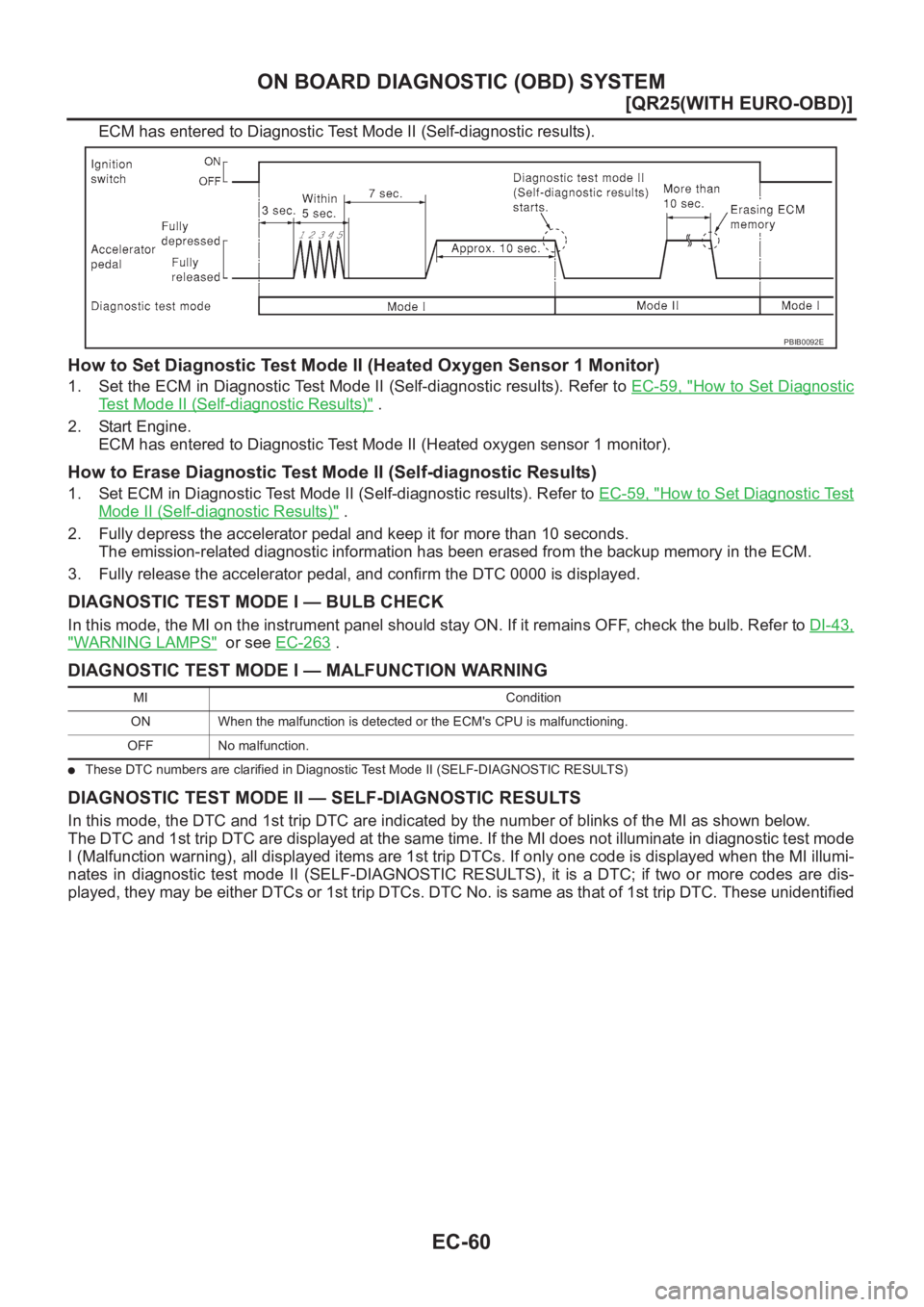
How to Set Diagnostic Test Mode II (Self-diagnostic Results)
1. Confirm that accelerator pedal is fully released, turn ignition switch “ON” and wait 3 seconds.
2. Repeat the following procedure quickly five times within 5 seconds.
a. Fully depress the accelerator pedal.
b. Fully release the accelerator pedal.
3. Wait 7 seconds, fully depress the accelerator pedal and keep it for approx. 10 seconds until the MI starts
blinking.
4. Fully release the accelerator pedal.
Mode II Ignition switch in
“ON” position
Engine stoppedSELF-DIAGNOSTIC
RESULTSThis function allows DTCs and 1st trip DTCs to be read.
Engine running HEATED OXYGEN SENSOR 1
MONITORThis function allows the fuel mixture condition (lean or
rich), monitored by heated oxygen sensor 1, to be read. Diagnostic Test
ModeKEY and ENG.
StatusFunction Explanation of Function
Page 410 of 3833
EC-60
[QR25(WITH EURO-OBD)]
ON BOARD DIAGNOSTIC (OBD) SYSTEM
ECM has entered to Diagnostic Test Mode II (Self-diagnostic results).
How to Set Diagnostic Test Mode II (Heated Oxygen Sensor 1 Monitor)
1. Set the ECM in Diagnostic Test Mode II (Self-diagnostic results). Refer to EC-59, "How to Set Diagnostic
Test Mode II (Self-diagnostic Results)" .
2. Start Engine.
ECM has entered to Diagnostic Test Mode II (Heated oxygen sensor 1 monitor).
How to Erase Diagnostic Test Mode II (Self-diagnostic Results)
1. Set ECM in Diagnostic Test Mode II (Self-diagnostic results). Refer to EC-59, "How to Set Diagnostic Test
Mode II (Self-diagnostic Results)" .
2. Fully depress the accelerator pedal and keep it for more than 10 seconds.
The emission-related diagnostic information has been erased from the backup memory in the ECM.
3. Fully release the accelerator pedal, and confirm the DTC 0000 is displayed.
DIAGNOSTIC TEST MODE I — BULB CHECK
In this mode, the MI on the instrument panel should stay ON. If it remains OFF, check the bulb. Refer to DI-43,
"WARNING LAMPS" or see EC-263 .
DIAGNOSTIC TEST MODE I — MALFUNCTION WARNING
●These DTC numbers are clarified in Diagnostic Test Mode II (SELF-DIAGNOSTIC RESULTS)
DIAGNOSTIC TEST MODE II — SELF-DIAGNOSTIC RESULTS
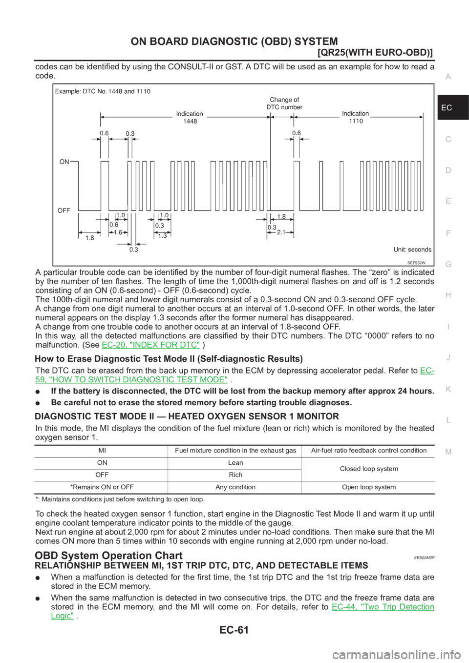
In this mode, the DTC and 1st trip DTC are indicated by the number of blinks of the MI as shown below.
The DTC and 1st trip DTC are displayed at the same time. If the MI does not illuminate in diagnostic test mode
I (Malfunction warning), all displayed items are 1st trip DTCs. If only one code is displayed when the MI illumi-
nates in diagnostic test mode II (SELF-DIAGNOSTIC RESULTS), it is a DTC; if two or more codes are dis-
played, they may be either DTCs or 1st trip DTCs. DTC No. is same as that of 1st trip DTC. These unidentified
PBIB0092E
MI Condition
ON When the malfunction is detected or the ECM's CPU is malfunctioning.
OFF No malfunction.
Page 411 of 3833
ON BOARD DIAGNOSTIC (OBD) SYSTEM
EC-61
[QR25(WITH EURO-OBD)]
C
D
E
F
G
H
I
J
K
L
MA
EC
codes can be identified by using the CONSULT-II or GST. A DTC will be used as an example for how to read a
code.
A particular trouble code can be identified by the number of four-digit numeral flashes. The “zero” is indicated
by the number of ten flashes. The length of time the 1,000th-digit numeral flashes on and off is 1.2 seconds
consisting of an ON (0.6-second) - OFF (0.6-second) cycle.
The 100th-digit numeral and lower digit numerals consist of a 0.3-second ON and 0.3-second OFF cycle.
A change from one digit numeral to another occurs at an interval of 1.0-second OFF. In other words, the later
numeral appears on the display 1.3 seconds after the former numeral has disappeared.
A change from one trouble code to another occurs at an interval of 1.8-second OFF.
In this way, all the detected malfunctions are classified by their DTC numbers. The DTC “0000” refers to no
malfunction. (See EC-20, "
INDEX FOR DTC" )
How to Erase Diagnostic Test Mode II (Self-diagnostic Results)
The DTC can be erased from the back up memory in the ECM by depressing accelerator pedal. Refer to EC-
59, "HOW TO SWITCH DIAGNOSTIC TEST MODE" .
●If the battery is disconnected, the DTC will be lost from the backup memory after approx 24 hours.
●Be careful not to erase the stored memory before starting trouble diagnoses.
DIAGNOSTIC TEST MODE II — HEATED OXYGEN SENSOR 1 MONITOR
In this mode, the MI displays the condition of the fuel mixture (lean or rich) which is monitored by the heated
oxygen sensor 1.
*: Maintains conditions just before switching to open loop.
To check the heated oxygen sensor 1 function, start engine in the Diagnostic Test Mode II and warm it up until
engine coolant temperature indicator points to the middle of the gauge.
Next run engine at about 2,000 rpm for about 2 minutes under no-load conditions. Then make sure that the MI
comes ON more than 5 times within 10 seconds with engine running at 2,000 rpm under no-load.
OBD System Operation ChartEBS00M0R
RELATIONSHIP BETWEEN MI, 1ST TRIP DTC, DTC, AND DETECTABLE ITEMS
●When a malfunction is detected for the first time, the 1st trip DTC and the 1st trip freeze frame data are
stored in the ECM memory.
●When the same malfunction is detected in two consecutive trips, the DTC and the freeze frame data are
stored in the ECM memory, and the MI will come on. For details, refer to EC-44, "
Two Trip Detection
Logic" .
SEF952W
MI Fuel mixture condition in the exhaust gas Air-fuel ratio feedback control condition
ON Lean
Closed loop system
OFF Rich
*Remains ON or OFF Any condition Open loop system