ECO mode NISSAN X-TRAIL 2001 Service Owner's Manual
[x] Cancel search | Manufacturer: NISSAN, Model Year: 2001, Model line: X-TRAIL, Model: NISSAN X-TRAIL 2001Pages: 3833, PDF Size: 39.49 MB
Page 412 of 3833
EC-62
[QR25(WITH EURO-OBD)]
ON BOARD DIAGNOSTIC (OBD) SYSTEM
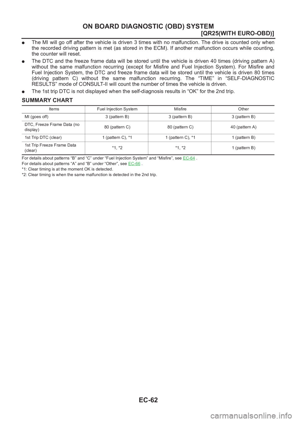
●The MI will go off after the vehicle is driven 3 times with no malfunction. The drive is counted only when
the recorded driving pattern is met (as stored in the ECM). If another malfunction occurs while counting,
the counter will reset.
●The DTC and the freeze frame data will be stored until the vehicle is driven 40 times (driving pattern A)
without the same malfunction recurring (except for Misfire and Fuel Injection System). For Misfire and
Fuel Injection System, the DTC and freeze frame data will be stored until the vehicle is driven 80 times
(driving pattern C) without the same malfunction recurring. The “TIME” in “SELF-DIAGNOSTIC
RESULTS” mode of CONSULT-II will count the number of times the vehicle is driven.
●The 1st trip DTC is not displayed when the self-diagnosis results in “OK” for the 2nd trip.
SUMMARY CHART
For details about patterns “B” and “C” under “Fuel Injection System” and “Misfire”, see EC-64 .
For details about patterns “A” and “B” under “Other”, see EC-66
.
*1: Clear timing is at the moment OK is detected.
*2: Clear timing is when the same malfunction is detected in the 2nd trip. Items Fuel Injection System Misfire Other
MI (goes off) 3 (pattern B) 3 (pattern B) 3 (pattern B)
DTC, Freeze Frame Data (no
display)80 (pattern C) 80 (pattern C) 40 (pattern A)
1st Trip DTC (clear) 1 (pattern C), *1 1 (pattern C), *1 1 (pattern B)
1st Trip Freeze Frame Data
(clear)*1, *2 *1, *2 1 (pattern B)
Page 448 of 3833
EC-98
[QR25(WITH EURO-OBD)]
TROUBLE DIAGNOSIS
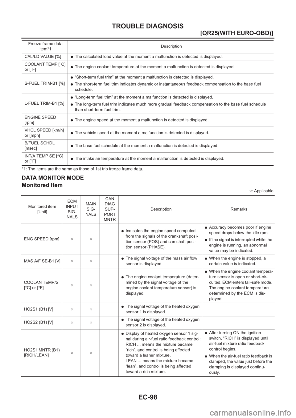
*1: The items are the same as those of 1st trip freeze frame data.
DATA MONITOR MODE
Monitored Item
×: Applicable CAL/LD VALUE [%]
●The calculated load value at the moment a malfunction is detected is displayed.
COOLANT TEMP [°C]
or [°F]
●The engine coolant temperature at the moment a malfunction is detected is displayed.
S-FUEL TRIM-B1 [%]
●“Short-term fuel trim” at the moment a malfunction is detected is displayed.
●The short-term fuel trim indicates dynamic or instantaneous feedback compensation to the base fuel
schedule.
L-FUEL TRIM-B1 [%]
●“Long-term fuel trim” at the moment a malfunction is detected is displayed.
●The long-term fuel trim indicates much more gradual feedback compensation to the base fuel schedule
than short-term fuel trim.
ENGINE SPEED
[rpm]
●The engine speed at the moment a malfunction is detected is displayed.
VHCL SPEED [km/h]
or [mph]
●The vehicle speed at the moment a malfunction is detected is displayed.
B/FUEL SCHDL
[msec]
●The base fuel schedule at the moment a malfunction is detected is displayed.
INT/A TEMP SE [°C]
or [°F]
●The intake air temperature at the moment a malfunction is detected is displayed. Freeze frame data
item*1Description
Monitored item
[Unit]ECM
INPUT
SIG-
NALSMAIN
SIG-
NALSCAN
DIAG
SUP-
PORT
MNTRDescription Remarks
ENG SPEED [rpm]××
●Indicates the engine speed computed
from the signals of the crankshaft posi-
tion sensor (POS) and camshaft posi-
tion sensor (PHASE).●Accuracy becomes poor if engine
speed drops below the idle rpm.
●If the signal is interrupted while the
engine is running, an abnormal
value may be indicated.
MAS A/F SE-B1 [V]××
●The signal voltage of the mass air flow
sensor is displayed.●When the engine is stopped, a
certain value is indicated.
COOLAN TEMP/S
[°C] or [°F]××
●The engine coolant temperature (deter-
mined by the signal voltage of the
engine coolant temperature sensor) is
displayed.
●When the engine coolant tempera-
ture sensor is open or short-cir-
cuited, ECM enters fail-safe mode.
The engine coolant temperature
determined by the ECM is dis-
played.
HO2S1 (B1) [V]××
●The signal voltage of the heated oxygen
sensor 1 is displayed.
HO2S2 (B1) [V]××
●The signal voltage of the heated oxygen
sensor 2 is displayed.
HO2S1 MNTR (B1)
[RICH/LEAN]××
●Display of heated oxygen sensor 1 sig-
nal during air-fuel ratio feedback control:
RICH ... means the mixture became
“rich”, and control is being affected
toward a leaner mixture.
LEAN ... means the mixture became
“lean”, and control is being affected
toward a rich mixture.●After turning ON the ignition
switch, “RICH” is displayed until
air-fuel mixture ratio feedback
control begins.
●When the air-fuel ratio feedback is
clamped, the value just before the
clamping is displayed continu-
ously.
Page 453 of 3833
TROUBLE DIAGNOSIS
EC-103
[QR25(WITH EURO-OBD)]
C
D
E
F
G
H
I
J
K
L
MA
EC
DTC & SRT CONFIRMATION MODE
SRT STATUS Mode
For details, refer to EC-48, "SYSTEM READINESS TEST (SRT) CODE" .
SRT Work Support Mode
This mode enables a technician to drive a vehicle to set the SRT while monitoring the SRT status.
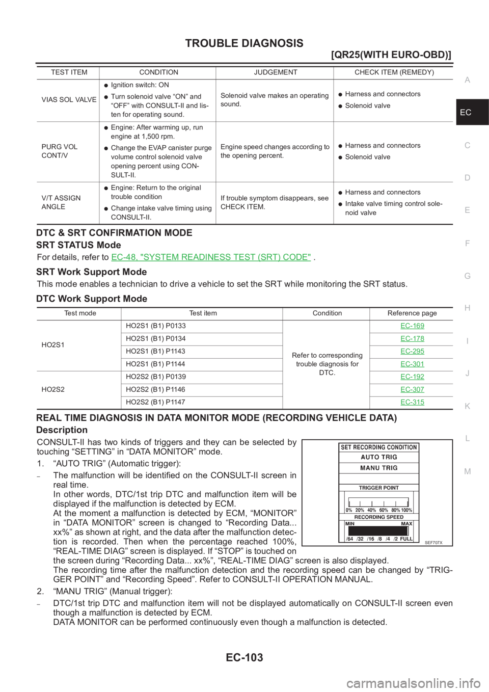
DTC Work Support Mode
REAL TIME DIAGNOSIS IN DATA MONITOR MODE (RECORDING VEHICLE DATA)
Description
CONSULT-II has two kinds of triggers and they can be selected by
touching “SETTING” in “DATA MONITOR” mode.
1. “AUTO TRIG” (Automatic trigger):
–The malfunction will be identified on the CONSULT-II screen in
real time.
In other words, DTC/1st trip DTC and malfunction item will be
displayed if the malfunction is detected by ECM.
At the moment a malfunction is detected by ECM, “MONITOR”
in “DATA MONITOR” screen is changed to “Recording Data...
xx%” as shown at right, and the data after the malfunction detec-
tion is recorded. Then when the percentage reached 100%,
“REAL-TIME DIAG” screen is displayed. If “STOP” is touched on
the screen during “Recording Data... xx%”, “REAL-TIME DIAG” screen is also displayed.
The recording time after the malfunction detection and the recording speed can be changed by “TRIG-
GER POINT” and “Recording Speed”. Refer to CONSULT-II OPERATION MANUAL.
2. “MANU TRIG” (Manual trigger):
–DTC/1st trip DTC and malfunction item will not be displayed automatically on CONSULT-II screen even
though a malfunction is detected by ECM.
DATA MONITOR can be performed continuously even though a malfunction is detected.
VIAS SOL VALVE
●Ignition switch: ON
●Turn solenoid valve “ON” and
“OFF” with CONSULT-II and lis-
ten for operating sound.Solenoid valve makes an operating
sound.●Harness and connectors
●Solenoid valve
PURG VOL
CONT/V
●Engine: After warming up, run
engine at 1,500 rpm.
●Change the EVAP canister purge
volume control solenoid valve
opening percent using CON-
SULT-II.Engine speed changes according to
the opening percent.●Harness and connectors
●Solenoid valve
V/T ASSIGN
ANGLE
●Engine: Return to the original
trouble condition
●Change intake valve timing using
CONSULT-II.If trouble symptom disappears, see
CHECK ITEM.
●Harness and connectors
●Intake valve timing control sole-
noid valve TEST ITEM CONDITION JUDGEMENT CHECK ITEM (REMEDY)
Test mode Test item Condition Reference page
HO2S1HO2S1 (B1) P0133
Refer to corresponding
trouble diagnosis for
DTC.EC-169
HO2S1 (B1) P0134EC-178
HO2S1 (B1) P1143EC-295
HO2S1 (B1) P1144EC-301
HO2S2HO2S2 (B1) P0139EC-192HO2S2 (B1) P1146EC-307
HO2S2 (B1) P1147EC-315
SEF706XSEF707X
Page 456 of 3833
EC-106
[QR25(WITH EURO-OBD)]
TROUBLE DIAGNOSIS
5. Perform each diagnostic mode according to each service proce-
dure.
For further information, see the GST Operation Manual of the
tool maker.
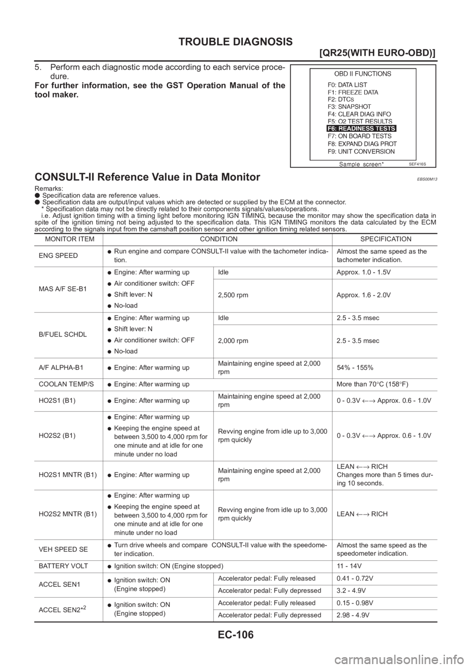
CONSULT-II Reference Value in Data MonitorEBS00M13
Remarks:
● Specification data are reference values.
● Specification data are output/input values which are detected or supplied by the ECM at the connector.
* Specification data may not be directly related to their components signals/values/operations.
i.e. Adjust ignition timing with a timing light before monitoring IGN TIMING, because the monitor may show the specification data in
spite of the ignition timing not being adjusted to the specification data. This IGN TIMING monitors the data calculated by the ECM
according to the signals input from the camshaft position sensor and other ignition timing related sensors.
SEF416S
MONITOR ITEM CONDITION SPECIFICATION
ENG SPEED
●Run engine and compare CONSULT-II value with the tachometer indica-
tion.Almost the same speed as the
tachometer indication.
MAS A/F SE-B1
●Engine: After warming up
●Air conditioner switch: OFF
●Shift lever: N
●No-loadIdle Approx. 1.0 - 1.5V
2,500 rpm Approx. 1.6 - 2.0V
B/FUEL SCHDL
●Engine: After warming up
●Shift lever: N
●Air conditioner switch: OFF
●No-loadIdle 2.5 - 3.5 msec
2,000 rpm 2.5 - 3.5 msec
A/F ALPHA-B1
●Engine: After warming upMaintaining engine speed at 2,000
rpm54% - 155%
COOLAN TEMP/S
●Engine: After warming up More than 70°C (158°F)
HO2S1 (B1)
●Engine: After warming upMaintaining engine speed at 2,000
rpm0 - 0.3V ←→ Approx. 0.6 - 1.0V
HO2S2 (B1)
●Engine: After warming up
●Keeping the engine speed at
between 3,500 to 4,000 rpm for
one minute and at idle for one
minute under no loadRevving engine from idle up to 3,000
rpm quickly0 - 0.3V ←→ Approx. 0.6 - 1.0V
HO2S1 MNTR (B1)
●Engine: After warming upMaintaining engine speed at 2,000
rpmLEAN ←→ RICH
Changes more than 5 times dur-
ing 10 seconds.
HO2S2 MNTR (B1)
●Engine: After warming up
●Keeping the engine speed at
between 3,500 to 4,000 rpm for
one minute and at idle for one
minute under no loadRevving engine from idle up to 3,000
rpm quicklyLEAN ←→ RICH
VEH SPEED SE
●Turn drive wheels and compare CONSULT-II value with the speedome-
ter indication.Almost the same speed as the
speedometer indication.
BATTERY VOLT
●Ignition switch: ON (Engine stopped) 11 - 14V
ACCEL SEN1
●Ignition switch: ON
(Engine stopped)Accelerator pedal: Fully released 0.41 - 0.72V
Accelerator pedal: Fully depressed 3.2 - 4.9V
ACCEL SEN2*
2●Ignition switch: ON
(Engine stopped)Accelerator pedal: Fully released 0.15 - 0.98V
Accelerator pedal: Fully depressed 2.98 - 4.9V
Page 458 of 3833
EC-108
[QR25(WITH EURO-OBD)]
TROUBLE DIAGNOSIS
*1: These items are not applied for M/T models.
*2: Accelerator pedal position sensor 2 signal and throttle position sensor 2 signal are converted by ECM internally. Thus, they differ
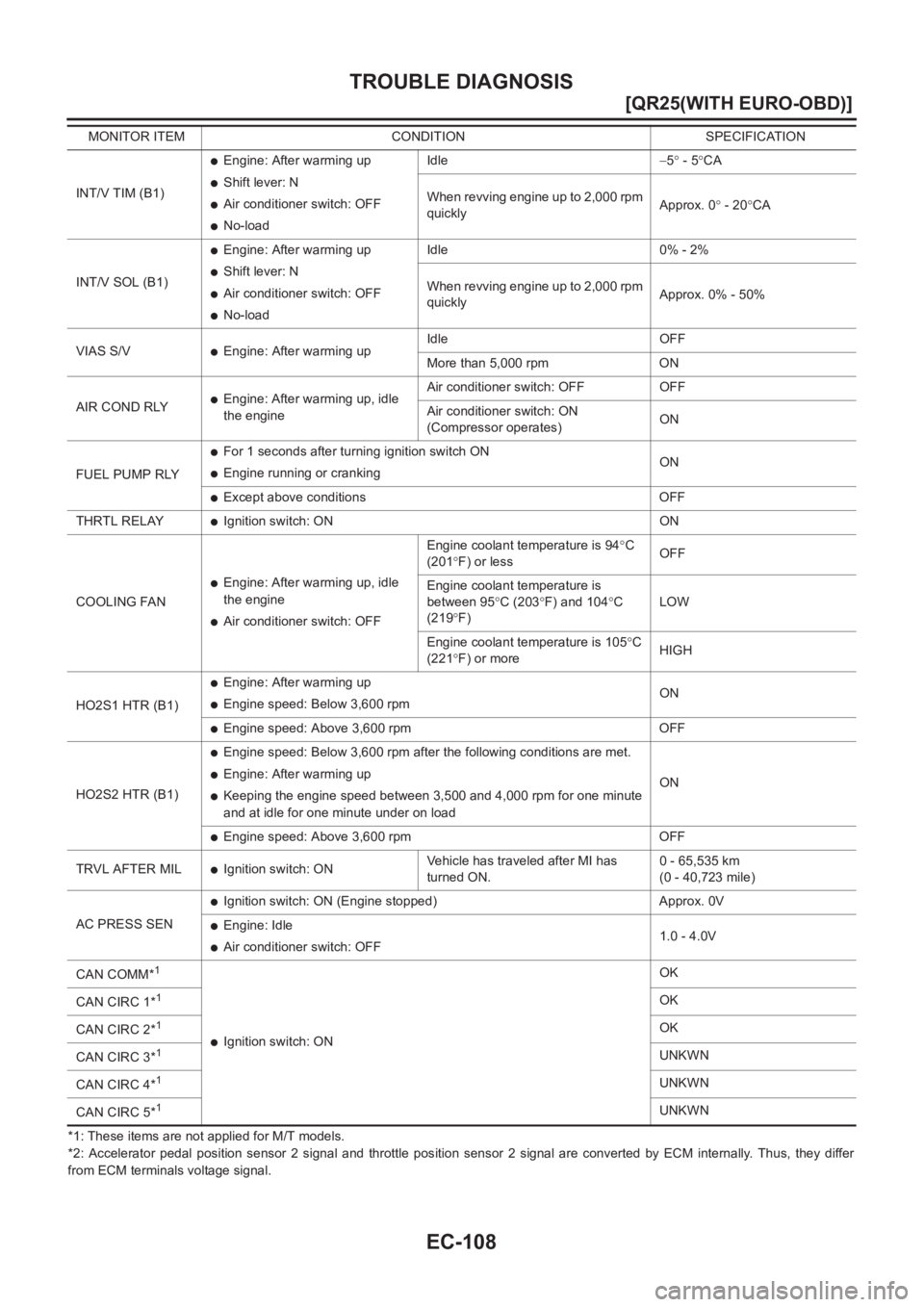
from ECM terminals voltage signal.INT/V TIM (B1)
●Engine: After warming up
●Shift lever: N
●Air conditioner switch: OFF
●No-loadIdle−5° - 5°CA
When revving engine up to 2,000 rpm
quicklyApprox. 0° - 20°CA
INT/V SOL (B1)
●Engine: After warming up
●Shift lever: N
●Air conditioner switch: OFF
●No-loadIdle 0% - 2%
When revving engine up to 2,000 rpm
quicklyApprox. 0% - 50%
VIAS S/V
●Engine: After warming upIdle OFF
More than 5,000 rpm ON
AIR COND RLY
●Engine: After warming up, idle
the engineAir conditioner switch: OFF OFF
Air conditioner switch: ON
(Compressor operates)ON
FUEL PUMP RLY
●For 1 seconds after turning ignition switch ON
●Engine running or crankingON
●Except above conditions OFF
THRTL RELAY
●Ignition switch: ON ON
COOLING FAN
●Engine: After warming up, idle
the engine
●Air conditioner switch: OFFEngine coolant temperature is 94°C
(201°F) or lessOFF
Engine coolant temperature is
between 95°C (203°F) and 104°C
(219°F)LOW
Engine coolant temperature is 105°C
(221°F) or moreHIGH
HO2S1 HTR (B1)
●Engine: After warming up
●Engine speed: Below 3,600 rpmON
●Engine speed: Above 3,600 rpm OFF
HO2S2 HTR (B1)
●Engine speed: Below 3,600 rpm after the following conditions are met.
●Engine: After warming up
●Keeping the engine speed between 3,500 and 4,000 rpm for one minute
and at idle for one minute under on loadON
●Engine speed: Above 3,600 rpm OFF
TRVL AFTER MIL
●Ignition switch: ONVehicle has traveled after MI has
turned ON.0 - 65,535 km
(0 - 40,723 mile)
AC PRESS SEN
●Ignition switch: ON (Engine stopped) Approx. 0V
●Engine: Idle
●Air conditioner switch: OFF1.0 - 4.0V
CAN COMM*
1
●Ignition switch: ONOK
CAN CIRC 1*
1OK
CAN CIRC 2*
1OK
CAN CIRC 3*
1UNKWN
CAN CIRC 4*
1UNKWN
CAN CIRC 5*
1UNKWN MONITOR ITEM CONDITION SPECIFICATION
Page 472 of 3833
EC-122
[QR25(WITH EURO-OBD)]
DTC U1000 CAN COMMUNICATION LINE
DTC U1000 CAN COMMUNICATION LINE
PFP:23710
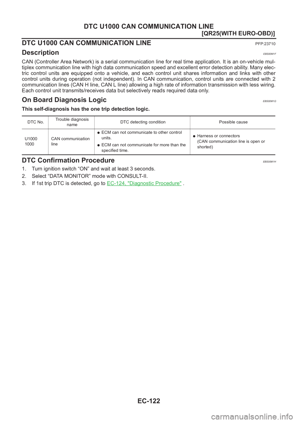
DescriptionEBS00M1F
CAN (Controller Area Network) is a serial communication line for real time application. It is an on-vehicle mul-
tiplex communication line with high data communication speed and excellent error detection ability. Many elec-
tric control units are equipped onto a vehicle, and each control unit shares information and links with other
control units during operation (not independent). In CAN communication, control units are connected with 2
communication lines (CAN H line, CAN L line) allowing a high rate of information transmission with less wiring.
Each control unit transmits/receives data but selectively reads required data only.
On Board Diagnosis LogicEBS00M1G
This self-diagnosis has the one trip detection logic.
DTC Confirmation ProcedureEBS00M1H
1. Turn ignition switch “ON” and wait at least 3 seconds.
2. Select “DATA MONITOR” mode with CONSULT-II.
3. If 1st trip DTC is detected, go to EC-124, "
Diagnostic Procedure" .
DTC No.Trouble diagnosis
nameDTC detecting condition Possible cause
U1000
1000CAN communication
line
●ECM can not communicate to other control
units.
●ECM can not communicate for more than the
specified time.
●Harness or connectors
(CAN communication line is open or
shorted)
Page 476 of 3833
EC-126
[QR25(WITH EURO-OBD)]
DTC P0011 IVT CONTROL
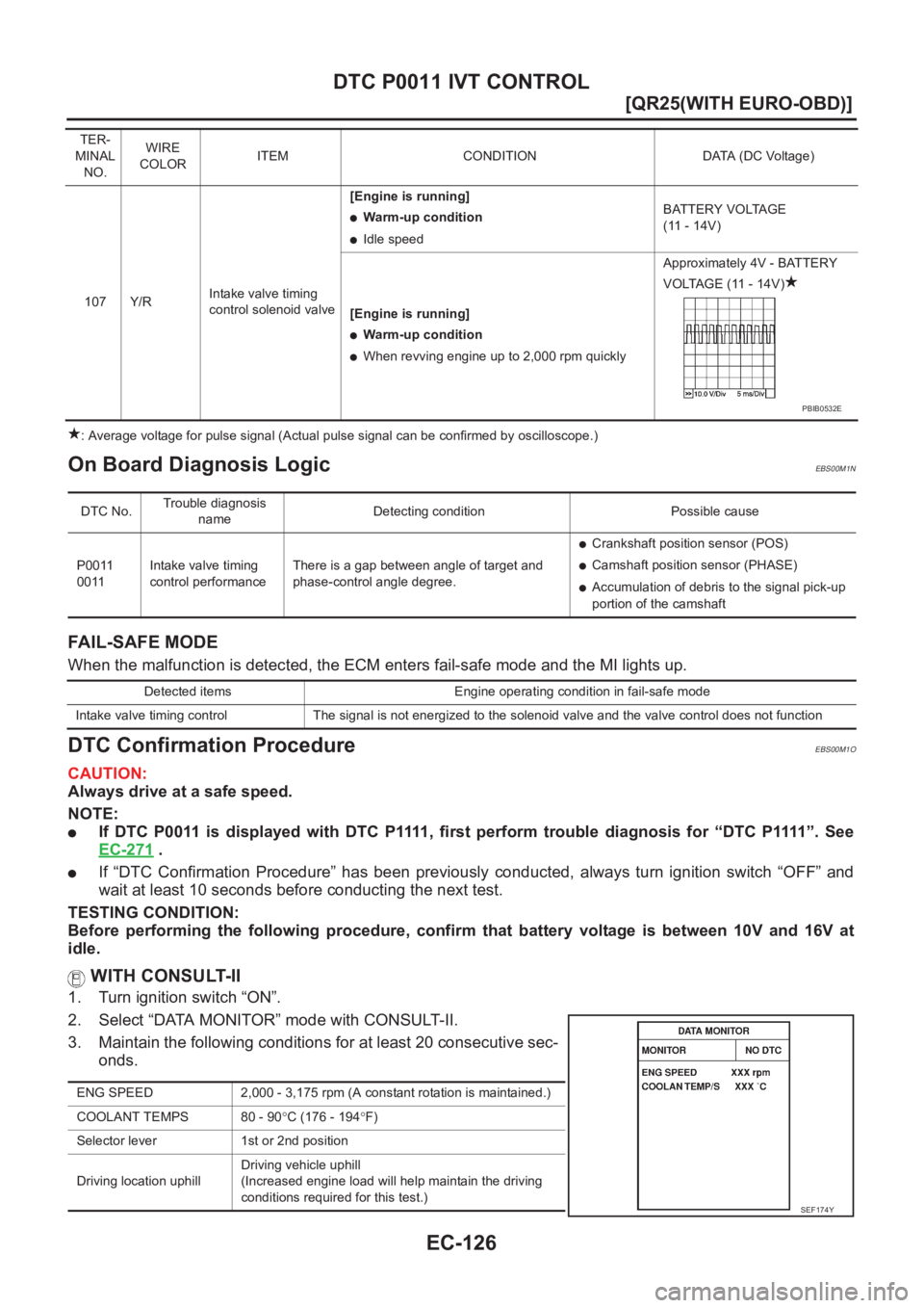
: Average voltage for pulse signal (Actual pulse signal can be confirmed by oscilloscope.)
On Board Diagnosis LogicEBS00M1N
FAIL-SAFE MODE
When the malfunction is detected, the ECM enters fail-safe mode and the MI lights up.
DTC Confirmation ProcedureEBS00M1O
CAUTION:
Always drive at a safe speed.
NOTE:
●If DTC P0011 is displayed with DTC P1111, first perform trouble diagnosis for “DTC P1111”. See
EC-271
.
●If “DTC Confirmation Procedure” has been previously conducted, always turn ignition switch “OFF” and
wait at least 10 seconds before conducting the next test.
TESTING CONDITION:
Before performing the following procedure, confirm that battery voltage is between 10V and 16V at
idle.
WITH CONSULT-II
1. Turn ignition switch “ON”.
2. Select “DATA MONITOR” mode with CONSULT-II.
3. Maintain the following conditions for at least 20 consecutive sec-
onds.
TER-
MINAL
NO.WIRE
COLORITEM CONDITION DATA (DC Voltage)
107 Y/RIntake valve timing
control solenoid valve[Engine is running]
●Warm-up condition
●Idle speedBATTERY VOLTAGE
(11 - 14V)
[Engine is running]
●Warm-up condition
●When revving engine up to 2,000 rpm quicklyApproximately 4V - BATTERY
VOLTAGE (11 - 14V)
PBIB0532E
DTC No.Trouble diagnosis
nameDetecting condition Possible cause
P0011
0011Intake valve timing
control performanceThere is a gap between angle of target and
phase-control angle degree.
●Crankshaft position sensor (POS)
●Camshaft position sensor (PHASE)
●Accumulation of debris to the signal pick-up
portion of the camshaft
Detected items Engine operating condition in fail-safe mode
Intake valve timing control The signal is not energized to the solenoid valve and the valve control does not function
ENG SPEED 2,000 - 3,175 rpm (A constant rotation is maintained.)
COOLANT TEMPS 80 - 90°C (176 - 194°F)
Selector lever 1st or 2nd position
Driving location uphillDriving vehicle uphill
(Increased engine load will help maintain the driving
conditions required for this test.)
SEF174Y
Page 479 of 3833
DTC P0031, P0032 HO2S1 HEATER
EC-129
[QR25(WITH EURO-OBD)]
C
D
E
F
G
H
I
J
K
L
MA
EC
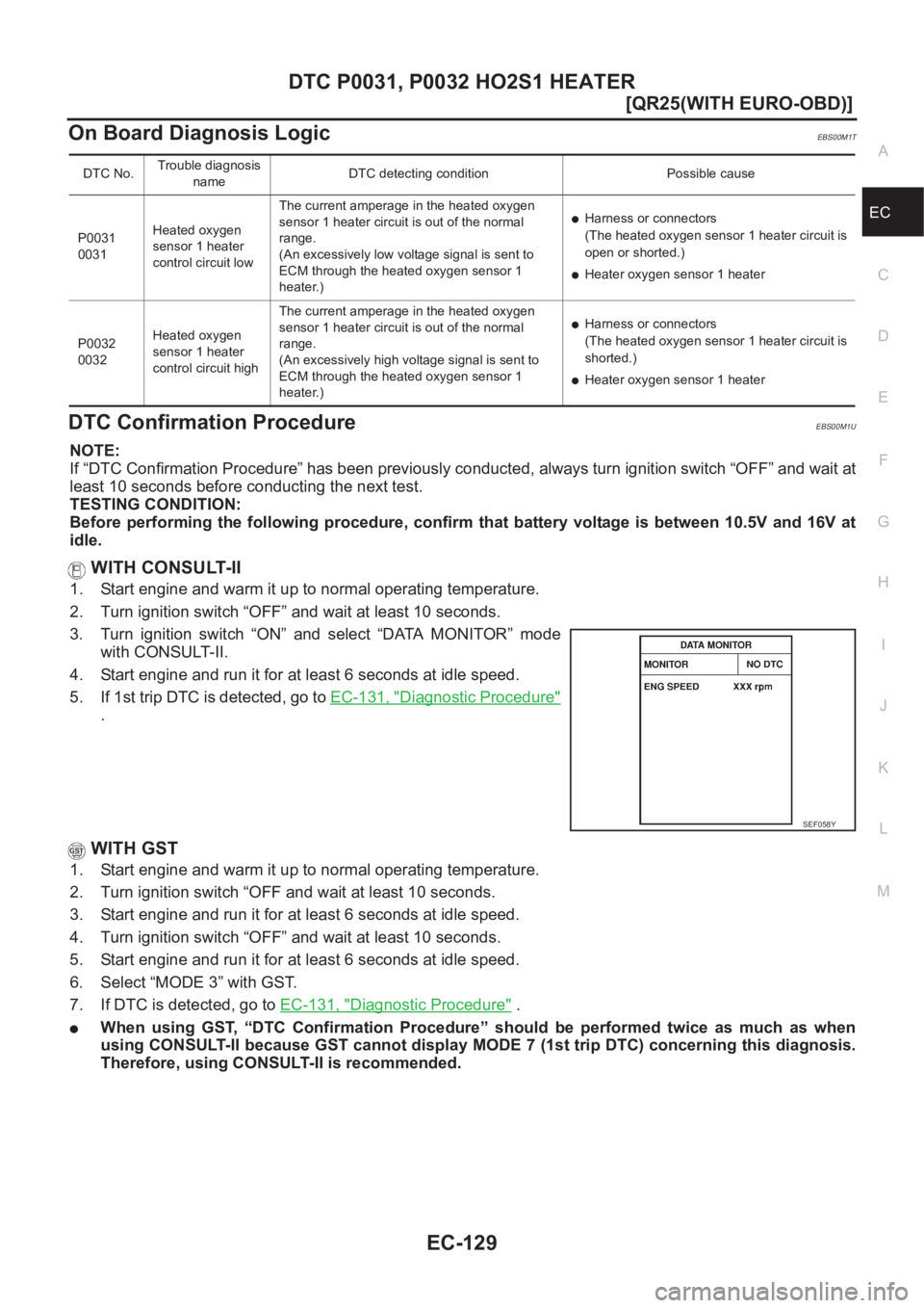
On Board Diagnosis LogicEBS00M1T
DTC Confirmation ProcedureEBS00M1U
NOTE:
If “DTC Confirmation Procedure” has been previously conducted, always turn ignition switch “OFF” and wait at
least 10 seconds before conducting the next test.
TESTING CONDITION:
Before performing the following procedure, confirm that battery voltage is between 10.5V and 16V at
idle.
WITH CONSULT-II
1. Start engine and warm it up to normal operating temperature.
2. Turn ignition switch “OFF” and wait at least 10 seconds.
3. Turn ignition switch “ON” and select “DATA MONITOR” mode
with CONSULT-II.
4. Start engine and run it for at least 6 seconds at idle speed.
5. If 1st trip DTC is detected, go to EC-131, "
Diagnostic Procedure"
.
WITH GST
1. Start engine and warm it up to normal operating temperature.
2. Turn ignition switch “OFF and wait at least 10 seconds.
3. Start engine and run it for at least 6 seconds at idle speed.
4. Turn ignition switch “OFF” and wait at least 10 seconds.
5. Start engine and run it for at least 6 seconds at idle speed.
6. Select “MODE 3” with GST.
7. If DTC is detected, go to EC-131, "
Diagnostic Procedure" .
●When using GST, “DTC Confirmation Procedure” should be performed twice as much as when
using CONSULT-II because GST cannot display MODE 7 (1st trip DTC) concerning this diagnosis.
Therefore, using CONSULT-II is recommended.
DTC No.Trouble diagnosis
nameDTC detecting condition Possible cause
P0031
0031Heated oxygen
sensor 1 heater
control circuit lowThe current amperage in the heated oxygen
sensor 1 heater circuit is out of the normal
range.
(An excessively low voltage signal is sent to
ECM through the heated oxygen sensor 1
heater.)
●Harness or connectors
(The heated oxygen sensor 1 heater circuit is
open or shorted.)
●Heater oxygen sensor 1 heater
P0032
0032Heated oxygen
sensor 1 heater
control circuit highThe current amperage in the heated oxygen
sensor 1 heater circuit is out of the normal
range.
(An excessively high voltage signal is sent to
ECM through the heated oxygen sensor 1
heater.)
●Harness or connectors
(The heated oxygen sensor 1 heater circuit is
shorted.)
●Heater oxygen sensor 1 heater
SEF058Y
Page 484 of 3833
EC-134
[QR25(WITH EURO-OBD)]
DTC P0037, P0038 HO2S2 HEATER
On Board Diagnosis Logic
EBS00M22
DTC Confirmation ProcedureEBS00M23
NOTE:
If “DTC Confirmation Procedure” has been previously conducted, always turn ignition switch “OFF” and wait at
least 10 seconds before conducting the next test.
TESTING CONDITION:
Before performing the following procedure, confirm that battery voltage is between 10.5V and 16V at
idle.
WITH CONSULT-II
1. Turn ignition switch “ON” and select “DATA MONITOR” mode with CONSULT-II.
2. Start engine and warm it up to the normal operating temperature.
3. Turn ignition switch ″OFF″ and wait at least 10 seconds.
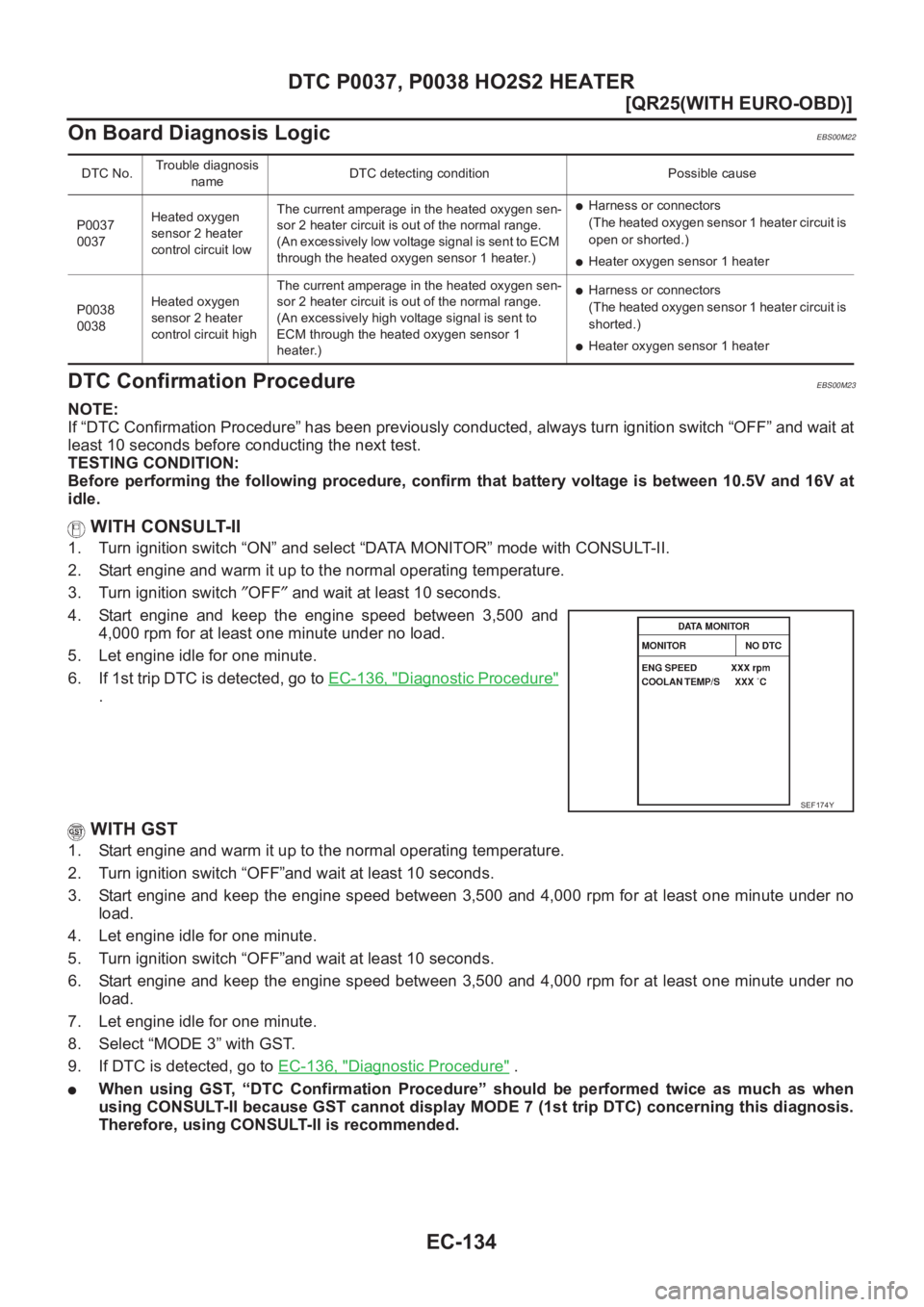
4. Start engine and keep the engine speed between 3,500 and
4,000 rpm for at least one minute under no load.
5. Let engine idle for one minute.
6. If 1st trip DTC is detected, go to EC-136, "
Diagnostic Procedure"
.
WITH GST
1. Start engine and warm it up to the normal operating temperature.
2. Turn ignition switch “OFF”and wait at least 10 seconds.
3. Start engine and keep the engine speed between 3,500 and 4,000 rpm for at least one minute under no
load.
4. Let engine idle for one minute.
5. Turn ignition switch “OFF”and wait at least 10 seconds.
6. Start engine and keep the engine speed between 3,500 and 4,000 rpm for at least one minute under no
load.
7. Let engine idle for one minute.
8. Select “MODE 3” with GST.
9. If DTC is detected, go to EC-136, "
Diagnostic Procedure" .
●When using GST, “DTC Confirmation Procedure” should be performed twice as much as when
using CONSULT-II because GST cannot display MODE 7 (1st trip DTC) concerning this diagnosis.
Therefore, using CONSULT-II is recommended.
DTC No.Trouble diagnosis
nameDTC detecting condition Possible cause
P0037
0037Heated oxygen
sensor 2 heater
control circuit lowThe current amperage in the heated oxygen sen-
sor 2 heater circuit is out of the normal range.
(An excessively low voltage signal is sent to ECM
through the heated oxygen sensor 1 heater.)
●Harness or connectors
(The heated oxygen sensor 1 heater circuit is
open or shorted.)
●Heater oxygen sensor 1 heater
P0038
0038Heated oxygen
sensor 2 heater
control circuit highThe current amperage in the heated oxygen sen-
sor 2 heater circuit is out of the normal range.
(An excessively high voltage signal is sent to
ECM through the heated oxygen sensor 1
heater.)
●Harness or connectors
(The heated oxygen sensor 1 heater circuit is
shorted.)
●Heater oxygen sensor 1 heater
SEF174Y
Page 489 of 3833
DTC P0102, P0103 MAF SENSOR
EC-139
[QR25(WITH EURO-OBD)]
C
D
E
F
G
H
I
J
K
L
MA
EC
FAIL-SAFE MODE
When the malfunction is detected, the ECM enters fail-safe mode and the MI lights up.
DTC Confirmation ProcedureEBS00M2C
NOTE:
If “DTC Confirmation Procedure” has been previously conducted, always turn ignition switch “OFF” and wait at
least 10 seconds before conducting the next test.
PROCEDURE FOR DTC P0102
With CONSULT-II
1. Turn ignition switch “ON”.
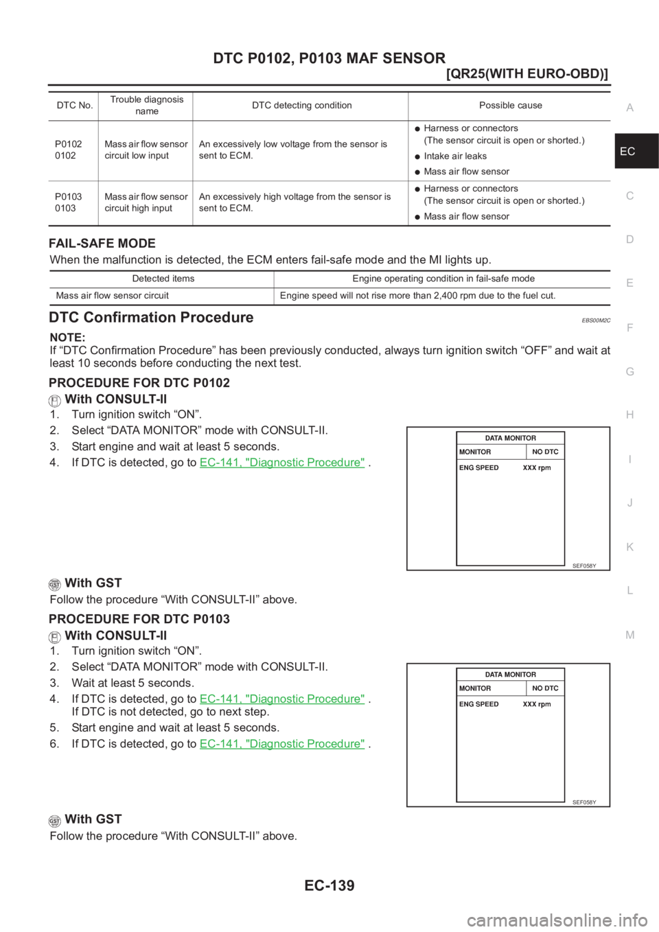
2. Select “DATA MONITOR” mode with CONSULT-II.
3. Start engine and wait at least 5 seconds.
4. If DTC is detected, go to EC-141, "
Diagnostic Procedure" .
With GST
Follow the procedure “With CONSULT-II” above.
PROCEDURE FOR DTC P0103
With CONSULT-II
1. Turn ignition switch “ON”.
2. Select “DATA MONITOR” mode with CONSULT-II.
3. Wait at least 5 seconds.
4. If DTC is detected, go to EC-141, "
Diagnostic Procedure" .
If DTC is not detected, go to next step.
5. Start engine and wait at least 5 seconds.
6. If DTC is detected, go to EC-141, "
Diagnostic Procedure" .
With GST
Follow the procedure “With CONSULT-II” above.
DTC No.Trouble diagnosis
nameDTC detecting condition Possible cause
P0102
0102Mass air flow sensor
circuit low inputAn excessively low voltage from the sensor is
sent to ECM.
●Harness or connectors
(The sensor circuit is open or shorted.)
●Intake air leaks
●Mass air flow sensor
P0103
0103Mass air flow sensor
circuit high inputAn excessively high voltage from the sensor is
sent to ECM.
●Harness or connectors
(The sensor circuit is open or shorted.)
●Mass air flow sensor
Detected items Engine operating condition in fail-safe mode
Mass air flow sensor circuit Engine speed will not rise more than 2,400 rpm due to the fuel cut.
SEF058Y
SEF058Y