fuel pressure NISSAN X-TRAIL 2001 Service User Guide
[x] Cancel search | Manufacturer: NISSAN, Model Year: 2001, Model line: X-TRAIL, Model: NISSAN X-TRAIL 2001Pages: 3833, PDF Size: 39.49 MB
Page 109 of 3833
![NISSAN X-TRAIL 2001 Service User Guide CYLINDER HEAD
EM-59
[QR]
C
D
E
F
G
H
I
J
K
L
MA
EM
CYLINDER HEADPFP:11041
On-Vehicle ServiceEBS00KNP
CHECKING COMPRESSION PRESSURE
1. Warm up engine thoroughly. Then, stop it.
2. Release fuel pressure](/img/5/57405/w960_57405-108.png "NISSAN X-TRAIL 2001 Service User Guide CYLINDER HEAD
EM-59
[QR]
C
D
E
F
G
H
I
J
K
L
MA
EM
CYLINDER HEADPFP:11041
On-Vehicle ServiceEBS00KNP
CHECKING COMPRESSION PRESSURE
1. Warm up engine thoroughly. Then, stop it.
2. Release fuel pressure")
CYLINDER HEAD
EM-59
[QR]
C
D
E
F
G
H
I
J
K
L
MA
EM
CYLINDER HEADPFP:11041
On-Vehicle ServiceEBS00KNP
CHECKING COMPRESSION PRESSURE
1. Warm up engine thoroughly. Then, stop it.
2. Release fuel pressure. Refer to EC-775, "
FUEL PRESSURE RELEASE" [QR20DE (WITH EURO-OBD)],
EC-1139, "
FUEL PRESSURE RELEASE" [QR20DE (WITHOUT EURO-OBD)], EC-42, "FUEL PRES-
SURE RELEASE" [QR25DE (WITH EURO-OBD)] or EC-452, "FUEL PRESSURE RELEASE" [QR25DE
(WITHOUT EURO-OBD)].
3. Remove ignition coil and spark plug from each cylinder. Refer to EM-29, "
IGNITION COIL" and EM-30,
"SPARK PLUG" .
4. Connect engine tachometer (not required in use of CONSULT-II).
5. Disconnect fuel injector sub-harness to avoid fuel injection dur-
ing measurement.
6. Install compression tester with adapter onto spark plug hole.
●Use compression gauge whose picking up end inserted to
spark plug hole is smaller than 20 mm (0.79 in) in diameter.
Otherwise, it may be caught by cylinder head during removal.
7. With accelerator pedal fully depressed, turn ignition switch to
“START” for cranking. When the gauge pointer stabilizes, read
the compression pressure and engine rpm. Perform these steps
to check each cylinder.
Compression pressure
Unit: kPa (bar, kg/cm2 , psi) /rpm
CAUTION:
Always use a fully changed battery to obtain specified engine speed.
KBIA0269E
KBIA0130E
SEM387C
Engine type Standard Minimum Deference limit between cylinders
QR20DE 1,190 (11.9, 12.1, 173) / 250 990 (9.9, 10.1, 144) / 250
100 (1.0, 1.0, 14) / 250
QR25DE 1,250 (12.5, 12.8, 181.3) / 250 1,060 (10.6, 10.8, 153.7) / 250
Page 110 of 3833
![NISSAN X-TRAIL 2001 Service User Guide EM-60
[QR]
CYLINDER HEAD
●If the engine speed is out of specified range, check battery liquid for proper gravity. Check engine
speed again with normal battery gravity.
●If compression](/img/5/57405/w960_57405-109.png "NISSAN X-TRAIL 2001 Service User Guide EM-60
[QR]
CYLINDER HEAD
●If the engine speed is out of specified range, check battery liquid for proper gravity. Check engine
speed again with normal battery gravity.
●If compression")
EM-60
[QR]
CYLINDER HEAD
●If the engine speed is out of specified range, check battery liquid for proper gravity. Check engine
speed again with normal battery gravity.
●If compression pressure is below minimum value, check valve clearances and parts associated with
combustion chamber (Valve, valve seat, piston, piston ring, cylinder bore, cylinder head, cylinder head
gasket). After the checking, measure compression pressure again.
●If some cylinders have low compression pressure, pour small amount of engine oil into the spark plug
hole of the cylinder to re-check it for compression.
–If the added engine oil improves the compression, the piston rings may be worn out or damaged. Check
the piston rings and replace if necessary.
–If the compression pressure remains at low level despite the addition of engine oil, the valves may be
malfunctioning. Check the valves for damage. Replace the valve or valve seat accordingly.
●If two adjacent cylinders have respectively low compression pressure and their compression remains
low even after the addition of engine oil, the gaskets are leaking. In such a case, replace the cylinder
head gaskets.
8. Install spark plug, ignition coil and harness connectors.
Removal and InstallationEBS00KNQ
REMOVAL
1. Release fuel pressure. Refer to EC-775, "FUEL PRESSURE RELEASE" [QR20DE (WITH EURO-OBD)],
EC-1139, "
FUEL PRESSURE RELEASE" [QR20DE (WITHOUT EURO-OBD)], EC-42, "FUEL PRES-
SURE RELEASE" [QR25DE (WITH EURO-OBD)] or EC-452, "FUEL PRESSURE RELEASE" [QR25DE
(WITHOUT EURO-OBD)].
2. Drain engine coolant and engine oil.
3. Remove the following components and related parts.
●Engine hood and engine undercover.
●Air cleaner case and air duct assembly; Refer to EM-14, "AIR CLEANER AND AIR DUCT" .
●Ignition coils; Refer to EM-29, "IGNITION COIL" .
●Rocker cover; Refer to EM-35, "ROCKER COVER" .
●Engine coolant reservoir tank
●Drive belt; Refer to EM-12, "REMOVAL" .
●Alternator
●Drive belt auto-tensioner; Refer to EM-13, "REMOVAL" .
●Exhaust front tube; Refer to EX-2, "Removal and Installation" .
●Exhaust manifold; Refer to EM-24, "EXHAUST MANIFOLD AND THREE WAY CATALYST" .
KBIA0250E
1. Cylinder head assembly 2. Cylinder head gasket 3. Cylinder head bolt
Page 120 of 3833
![NISSAN X-TRAIL 2001 Service User Guide EM-70
[QR]
ENGINE ASSEMBLY
1. Release fuel pressure. Refer to EC-775, "FUEL PRESSURE RELEASE" [QR20DE (WITH EURO-OBD)],
EC-1139, "
FUEL PRESSURE RELEASE" [QR20DE (WITHOUT EURO](/img/5/57405/w960_57405-119.png "NISSAN X-TRAIL 2001 Service User Guide EM-70
[QR]
ENGINE ASSEMBLY
1. Release fuel pressure. Refer to EC-775, \"FUEL PRESSURE RELEASE\" [QR20DE (WITH EURO-OBD)],
EC-1139, \"
FUEL PRESSURE RELEASE\" [QR20DE (WITHOUT EURO")
EM-70
[QR]
ENGINE ASSEMBLY
1. Release fuel pressure. Refer to EC-775, "FUEL PRESSURE RELEASE" [QR20DE (WITH EURO-OBD)],
EC-1139, "
FUEL PRESSURE RELEASE" [QR20DE (WITHOUT EURO-OBD)], EC-42, "FUEL PRES-
SURE RELEASE" [QR25DE (WITH EURO-OBD)] or EC-452, "FUEL PRESSURE RELEASE" [QR25DE
(WITHOUT EURO-OBD)].
2. Remove engine hood.
3. Drain engine coolant from radiator drain plug. Refer to CO-9, "
DRAINING ENGINE COOLANT" .
4. Remove the following parts.
●LH/RH undercovers
●LH/RH front wheels
●Battery
●Drive belts; Refer to EM-12, "REMOVAL" .
●Air duct and air cleaner case assembly; Refer to EM-14, "REMOVAL" .
●Alternator
●Radiator and radiator fan assembly; Refer to CO-11, "RADIATOR" .
5. Disconnect engine room harness from the engine side and set it aside for easier work.
6. Disconnect all the body-side vacuum hoses and air hoses at engine side.
Engine room LH
7. Disconnect fuel hose, and plug it to prevent fuel from draining. Refer to EM-16, "
INTAKE MANIFOLD"
8. Disconnect heater hose, and install plug it to prevent engine coolant from draining.
9. Disconnect select cable from transaxle (A/T models).
10. Remove clutch operating cylinder from transaxle, and move it aside (M/T models).
11. Disconnect shift cable from transaxle (M/T models).
Engine room RH
12. Remove engine coolant reservoir tank.
13. Remove air conditioner compressor with piping connected from engine. Temporarily secure it on body
with a rope to avoid putting load on it.
Vehicle underbody
14. Remove exhaust front tube.
15. Remove propeller shaft.
16. Remove steering shaft from steering gear.
17. Disconnect power steering fluid cooler piping at a point between body and engine.
18. Remove ABS sensor from brake caliper.
19. Remove brake caliper with piping connected from steering knuckle. Temporarily secure it on body with a
rope to avoid load on it.
20. Remove LH/RH suspensions from steering knuckle under strut.
Removal
21. Install engine slingers into front left of cylinder head and rear right of cylinder head.
●Use alternator bracket mounting bolt holes for the front side.
22. Lift with hoist and secure the engine in position.Slinger bolts:
Front
: 51.0 - 64.7 N·m (5.2 - 6.6 kg-m, 38 - 47 ft-lb)
Rear
: 24.5 - 31.4 N·m (2.5 - 3.2 kg-m, 18 - 23 ft-lb)
SBIA0271E
Page 125 of 3833
![NISSAN X-TRAIL 2001 Service User Guide CYLINDER BLOCK
EM-75
[QR]
C
D
E
F
G
H
I
J
K
L
MA
EM
●A commercial engine stand can be used.
NOTE:
This example is an engine stand for holding at transaxle
mounting side with the flywheel or](/img/5/57405/w960_57405-124.png "NISSAN X-TRAIL 2001 Service User Guide CYLINDER BLOCK
EM-75
[QR]
C
D
E
F
G
H
I
J
K
L
MA
EM
●A commercial engine stand can be used.
NOTE:
This example is an engine stand for holding at transaxle
mounting side with the flywheel or")
CYLINDER BLOCK
EM-75
[QR]
C
D
E
F
G
H
I
J
K
L
MA
EM
●A commercial engine stand can be used.
NOTE:
This example is an engine stand for holding at transaxle
mounting side with the flywheel or drive plate removed.
3. Drain engine oil and engine coolant from inside of engine.
4. Remove the following components and associated parts.
●Exhaust manifold and three way catalyst assembly; Refer to
EM-24, "
EXHAUST MANIFOLD AND THREE WAY CATA-
LYST" .
●Intake manifold collector; Refer to EM-16, "INTAKE MANI-
FOLD" .
●Intake manifold and fuel tube assembly; Refer to EM-16, "INTAKE MANIFOLD" .
●Ignition coil; Refer to EM-29, "IGNITION COIL" .
●Rocker cover; Refer to EM-35, "ROCKER COVER" .
●Oil pan and oil strainer; Refer to EM-26, "OIL PAN AND OIL STRAINER" .
●Front cover, timing chain and balancer unit; Refer to EM-37, "TIMING CHAIN" .
●Camshaft; Refer to EM-46, "CAMSHAFT" .
●Cylinder head; Refer to EM-59, "CYLINDER HEAD" .
5. Remove knock sensor.
CAUTION:
Carefully handle the sensor avoiding shocks.
6. Remove crankshaft position sensor (POS).
CAUTION:
●Avoid impacts such as a dropping.
●Do not disassemble.
●Keep it away from metal particles.
●Do not place sensor close to magnetic materials.
7. Remove flywheel (M/T model) or drive plate (A/T model). Fix crankshaft with a stopper plate, and remove
mounting bolts.
Torx bit (size T55): Flywheel (M/T model)
Torx socket (size T55): Drive plate (A/T model)
CAUTION:
Be careful not to damage contact surface for the clutch disc
of the flywheel.
NOTE:
The flywheels, two block construction, allows movement in
response to transmission side pressure, or when twisted in its
rotational direction. Therefore, some amount of noise is normal.
PBIC0085E
SBIA0273E
KBIA0062E
Page 160 of 3833
![NISSAN X-TRAIL 2001 Service User Guide EM-110
[YD22DDTi]
PRECAUTIONS
[YD22DDTi]PRECAUTIONSPFP:00001
Precautions for Drain Engine CoolantEBS00LQZ
Drain engine coolant when engine is cooled.
Precautions for Disconnecting Fuel PipingEBS00LR0](/img/5/57405/w960_57405-159.png "NISSAN X-TRAIL 2001 Service User Guide EM-110
[YD22DDTi]
PRECAUTIONS
[YD22DDTi]PRECAUTIONSPFP:00001
Precautions for Drain Engine CoolantEBS00LQZ
Drain engine coolant when engine is cooled.
Precautions for Disconnecting Fuel PipingEBS00LR0")
EM-110
[YD22DDTi]
PRECAUTIONS
[YD22DDTi]PRECAUTIONSPFP:00001
Precautions for Drain Engine CoolantEBS00LQZ
Drain engine coolant when engine is cooled.
Precautions for Disconnecting Fuel PipingEBS00LR0
●Before starting work, make sure no fire or spark producing items are in the work area.
●Release fuel pressure before disassembly.
●After disconnecting pipes, plug openings to stop fuel leakage.
Precautions for Removal and DisassemblyEBS00LR1
●When instructed to use special service tools, use the specified tools. Always be careful to work safely,
avoid forceful or uninstructed operations.
●Exercise maximum care to avoid damage to mating or sliding surfaces.
●Cover openings of engine system with tape or the equivalent, if necessary, to seal out foreign materials.
●Mark and arrange disassembly parts in an organized way for easy troubleshooting and re-assembly.
●When loosening nuts and bolts, as a basic rule, start with the one furthest outside, then the one diagonally
opposite, and so on. If the order of loosening is specified, do exactly as specified.
Precautions for Inspection, Repair and ReplacementEBS00LR2
Before repairing or replacing, thoroughly inspect parts. Inspect new replacement parts in the same way, and
replace if necessary.
Precautions for Assembly and InstallationEBS00LR3
●Use torque wrench to tighten bolts or nuts to specification.
●When tightening nuts and bolts, as a basic rule, equally tighten in several different steps starting with the
ones in center, then ones on inside and outside diagonally in this order. If the order of tightening is speci-
fied, do exactly as specified.
●Replace with new liquid gasket, packing, oil seal or O-ring.
●Thoroughly wash, clean, and air-blow each part. Carefully check engine oil or engine coolant passages for
any restriction and blockage.
●Avoid damaging sliding or mating surfaces. Completely remove foreign materials such as cloth lint or dust.
Before assembly, engine oil sliding surfaces well.
●Release air within route when refilling after draining coolant.
●After repairing, start engine and increase engine speed to check engine coolant, fuel, engine oil, and
exhaust systems for leakage.
Parts Requiring Angular TighteningEBS00LR4
●Use an angle wrench for the final tightening of the following engine parts:
–Cylinder head bolts
–Main bearing cap bolts
–Connecting rod cap nuts
–Crankshaft pulley bolt (No angle wrench is required as the bolt flange is provided with notches for angular
tightening)
●Do not use a torque value for final tightening.
●The torque value for these parts are for a preliminary step.
●Ensure thread and seat surfaces are clean and coated with engine oil.
Page 196 of 3833
![NISSAN X-TRAIL 2001 Service User Guide EM-146
[YD22DDTi]
INJECTION TUBE AND FUEL INJECTOR
2. Connect spill tube.
●Tighten fixing bolts and nut in the numerical order shown in
the figure.
NOTE:
Connection of spill tube gaske](/img/5/57405/w960_57405-195.png "NISSAN X-TRAIL 2001 Service User Guide EM-146
[YD22DDTi]
INJECTION TUBE AND FUEL INJECTOR
2. Connect spill tube.
●Tighten fixing bolts and nut in the numerical order shown in
the figure.
NOTE:
Connection of spill tube gaske")
EM-146
[YD22DDTi]
INJECTION TUBE AND FUEL INJECTOR
2. Connect spill tube.
●Tighten fixing bolts and nut in the numerical order shown in
the figure.
NOTE:
Connection of spill tube gasket may be broken, even if it is
tighten to specified torque. It does not affect performance.
3. Carry out air tightness test for spill tube.
●Connect a vacuum handy pump to spill connector. Check that
vacuum is retained while applying following vacuum.
●If outside of standard, reconnect spill tube. (Replace gasket in
this case.)
4. Install rocker cover. Refer to EM-156, "
Removal and Installation"
.
5. Install nozzle oil seal.
●Insert it straight until its flange fully contacts rocker cover.
CAUTION:
●Check gutter spring in nozzle oil seal on fuel injector for missing.
6. Connect injection tubes individually to each cylinder in order of
3-4-1-2.
7. Connect spill hose.
8. Install remaining parts in reverse order of removal.
INSPECTION AFTER INSTALLATION
CONSULT-ll service support has a force rail pressure increase function and can increase rail pressure to any
given pressure. Check for fuel leaks visually by increasing internal pressure using this function.
SBIA0205E
Standard:
− 53.3 to − 66.7 kPa (− 533 to − 667 mbar, − 400 to −
500 mmHg, −15.75 to − 19.69 inHg)
JEF250Z
SBIA0203E
Page 232 of 3833
![NISSAN X-TRAIL 2001 Service User Guide EM-182
[YD22DDTi]
CYLINDER HEAD
CYLINDER HEAD
PFP:11041
On-Vehicle ServiceEBS00LRV
CHECKING COMPRESSION PRESSURE
1. Warm up engine thoroughly. Then, stop it.
2. Using CONSULT-II, make sure no err](/img/5/57405/w960_57405-231.png "NISSAN X-TRAIL 2001 Service User Guide EM-182
[YD22DDTi]
CYLINDER HEAD
CYLINDER HEAD
PFP:11041
On-Vehicle ServiceEBS00LRV
CHECKING COMPRESSION PRESSURE
1. Warm up engine thoroughly. Then, stop it.
2. Using CONSULT-II, make sure no err")
EM-182
[YD22DDTi]
CYLINDER HEAD
CYLINDER HEAD
PFP:11041
On-Vehicle ServiceEBS00LRV
CHECKING COMPRESSION PRESSURE
1. Warm up engine thoroughly. Then, stop it.
2. Using CONSULT-II, make sure no error codes are indicated for self-diagnosis items. Refer to EC-1412,
"Basic Inspection" .
●Do not disconnect CONSULT-II until the end of this operation; it will be used to check engine rpm and
for error detection at the end of this operation.
3. Disconnect the negative battery terminal.
4. Remove charge air cooler. Refer to EM-122, "
Removal and Installation"
5. To prevent fuel from being injected during inspection, remove
fuel supply pump fuse [ENG CONT (20A)] from fuse box on the
left side of engine compartment.
●Among marks on fuse box, [ENG CONT 2 (20A)] is for fuel
supply pump fuse.
6. Remove glow plugs from all the cylinders. Refer to EM-138,
"Removal and Installation" .
CAUTION:
●Before removal, clean the surrounding area to prevent
entry of any foreign materials into the engine.
●Carefully remove glow plugs to prevent any damage or
breakage.
●Handle with care to avoid applying any shock to glow plugs.
7. Install adapter to installation holes of glow plugs and connect
compression gauge for diesel engine.
8. Connect battery negative terminal.
9. Set the ignition switch to “START” and crank. When gauge
pointer stabilizes, read compression pressure and engine rpm.
Repeat the above steps for each cylinder.
●Always use a fully-charged battery to obtain specified engine
speed.
Compression pressure
Unit: kPa (bar, kg/cm2 , psi)/rpm
●When engine rpm is out of the specified range, check the specific gravity of battery liquid. Measure
again under corrected conditions.
●If engine rpm exceeds the limit, check valve clearance and combustion chamber components (valves,
valve seats, cylinder head gaskets, piston rings, pistons, cylinder bores, cylinder block upper and lower
surfaces) and measure again.
●If compression pressure is low in some cylinders, apply engine oil from glow plug installation hole. Then
check pressure again.
–If compression pressure becomes normal after applying engine oil, piston ring may be worn or dam-
aged. Check piston ring for malfunction. If any, replace piston ring.
–If compression pressure is still low after applying engine oil, valve may be malfunctioning. Check valve
for malfunction. If contact malfunction is found, replace valve or valve seat.
●If compression pressure in adjacent two cylinders is low after applying engine oil, pressure may be
leaking from gasket. In this case, replace cylinder head gasket.
10. Complete this operation as follows:
PBIC0680E
: 18 - 21 N·m (1.8 - 2.2 kg-m, 13 - 15 ft-lb)
SEM112G
Standard Minimum Difference limit between cylinders
2,893 (28.9, 29.5, 419)/200 2,452 (24.52, 25.0, 356)/200 490 (4.90, 5.0, 71)/200
Page 280 of 3833
![NISSAN X-TRAIL 2001 Service User Guide EM-230
[YD22DDTi]
SERVICE DATA AND SPECIFICATIONS (SDS)
Common rail51.0 - 64.0 (5.2 - 6.5, 38 - 47)
Fuel supply pump51.0 - 56.0 (5.2 - 5.7, 38 - 41)
Fuel supply pump sprocket 37.0 - 41.0 (3.8 - 4.2, 2](/img/5/57405/w960_57405-279.png "NISSAN X-TRAIL 2001 Service User Guide EM-230
[YD22DDTi]
SERVICE DATA AND SPECIFICATIONS (SDS)
Common rail51.0 - 64.0 (5.2 - 6.5, 38 - 47)
Fuel supply pump51.0 - 56.0 (5.2 - 5.7, 38 - 41)
Fuel supply pump sprocket 37.0 - 41.0 (3.8 - 4.2, 2")
EM-230
[YD22DDTi]
SERVICE DATA AND SPECIFICATIONS (SDS)
Common rail51.0 - 64.0 (5.2 - 6.5, 38 - 47)
Fuel supply pump51.0 - 56.0 (5.2 - 5.7, 38 - 41)
Fuel supply pump sprocket 37.0 - 41.0 (3.8 - 4.2, 28 - 30)
Fuel supply pump rear bracket 27.0 - 37.0 (2.8 - 3.8, 20 - 27)
Front chain case
6.9 - 8.8 (0.7 - 0.9, 61 - 78)*
2
Chain tensioner
8.5 - 10.7 (0.86 - 1.1, 75 - 95)*2
Tension guide21.0 - 26.0 (2.1 - 2.7, 16 - 19)
Slack guide21.0 - 26.0 (2.1 - 2.7, 16 - 19)
Camshaft sprocket 138 - 147 (14.0 - 15.0, 102 - 108)
Fuel supply pump sprocket 38.0 - 41.0 (3.8 - 4.2, 28 - 30)
Oil pump12.0 - 13.0 (1.3 - 1.4, 9 - 10)
Power steering pump51.0 - 56.0 (5.2 - 5.8, 38 - 41)
Rear chain case12.0 - 13.0 (1.2 - 1.4, 19 - 10)
Engine coolant temperature sensor 12.0 - 15.0 (1.2 - 1.6, 9 - 11)
*1 Cylinder head 1) 29 - 38 (2.9 - 3.9, 21 - 28)
2) 180° to 185°
3) 0 (0, 0)
4) 35 to 44 (3.5 - 4.5, 26 - 32)
5) 90° to 95°(angle tightening)
6) 90° to 95° (angle tightening)
Water outlet21 - 28 (2.1 - 2.9, 16 - 20)
Glow plug18.0 - 21.0 (1.8 - 2.2, 13 - 15)
*1 Flywheel103 - 112 (10.5 - 11.5, 76 - 83)
Oil pressure switch13.0 - 17.0 (1.25 - 1.75, 9 - 12)
Oil jet6.1 - 10.7(0.62 - 1.1, 54 - 95)
Oil jet relief valve40 - 58 (4.0 - 6.0, 29 - 43)
Rear oil seal retainer12.0 - 13.0 (1.2 - 1.4, 9 - 10)
Page 351 of 3833
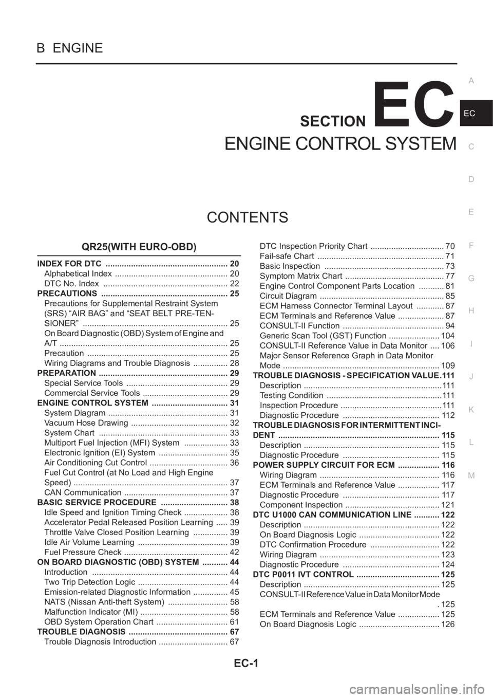
EC-1
ENGINE CONTROL SYSTEM
B ENGINE
CONTENTS
C
D
E
F
G
H
I
J
K
L
M
SECTION
A
EC
ENGINE CONTROL SYSTEM
QR25(WITH EURO-OBD)
INDEX FOR DTC ...................................................... 20
Alphabetical Index .................................................. 20
DTC No. Index ....................................................... 22
PRECAUTIONS ........................................................ 25
Precautions for Supplemental Restraint System
(SRS) “AIR BAG” and “SEAT BELT PRE-TEN-
SIONER” ................................................................ 25
On Board Diagnostic (OBD) System of Engine and
A/T .......................................................................... 25
Precaution .............................................................. 25
Wiring Diagrams and Trouble Diagnosis ................ 28
PREPARATION ......................................................... 29
Special Service Tools ............................................. 29
Commercial Service Tools ...................................... 29
ENGINE CONTROL SYSTEM .................................. 31
System Diagram ..................................................... 31
Vacuum Hose Drawing ........................................... 32
System Chart ......................................................... 33
Multiport Fuel Injection (MFI) System .................... 33
Electronic Ignition (EI) System ............................... 35
Air Conditioning Cut Control ................................... 36
Fuel Cut Control (at No Load and High Engine
Speed) .................................................................... 37
CAN Communication .............................................. 37
BASIC SERVICE PROCEDURE .............................. 38
Idle Speed and Ignition Timing Check .................... 38
Accelerator Pedal Released Position Learning ...... 39
Throttle Valve Closed Position Learning ................ 39
Idle Air Volume Learning ........................................ 39
Fuel Pressure Check .............................................. 42
ON BOARD DIAGNOSTIC (OBD) SYSTEM ............ 44
Introduction ............................................................ 44
Two Trip Detection Logic ........................................ 44
Emission-related Diagnostic Information ................ 45
NATS (Nissan Anti-theft System) ........................... 58
Malfunction Indicator (MI) ....................................... 58
OBD System Operation Chart ................................ 61
TROUBLE DIAGNOSIS ............................................ 67
Trouble Diagnosis Introduction ............................... 67DTC Inspection Priority Chart ................................. 70
Fail-safe Chart ........................................................ 71
Basic Inspection ..................................................... 73
Symptom Matrix Chart ............................................ 77
Engine Control Component Parts Location ............ 81
Circuit Diagram ....................................................... 85
ECM Harness Connector Terminal Layout ............. 87
ECM Terminals and Reference Value ..................
... 87
CONSULT-II Function ............................................. 94
Generic Scan Tool (GST) Function .......................104
CONSULT-II Reference Value in Data Monitor .....106
Major Sensor Reference Graph in Data Monitor
Mode .....................................................................109
TROUBLE DIAGNOSIS - SPECIFICATION VALUE ..111
Description .............................................................111
Testing Condition ...................................................111
Inspection Procedure .............................................111
Diagnostic Procedure ...........................................112
TROUBLE DIAGNOSIS FOR INTERMITTENT INCI-
DENT .......................................................................115
Description ............................................................115
Diagnostic Procedure ...........................................115
POWER SUPPLY CIRCUIT FOR ECM ...................116
Wiring Diagram .....................................................116
ECM Terminals and Reference Value ...................117
Diagnostic Procedure ...........................................117
Component Inspection ..........................................121
DTC U1000 CAN COMMUNICATION LINE ............122
Description ............................................................122
On Board Diagnosis Logic ....................................122
DTC Confirmation Procedure ...............................122
Wiring Diagram .....................................................123
Diagnostic Procedure ...........................................124
DTC P0011 IVT CONTROL .....................................125
Description ............................................................125
CONSULT-II Reference Value in Data Monitor Mode
.125
ECM Terminals and Reference Value ...................125
On Board Diagnosis Logic ....................................126
Page 355 of 3833
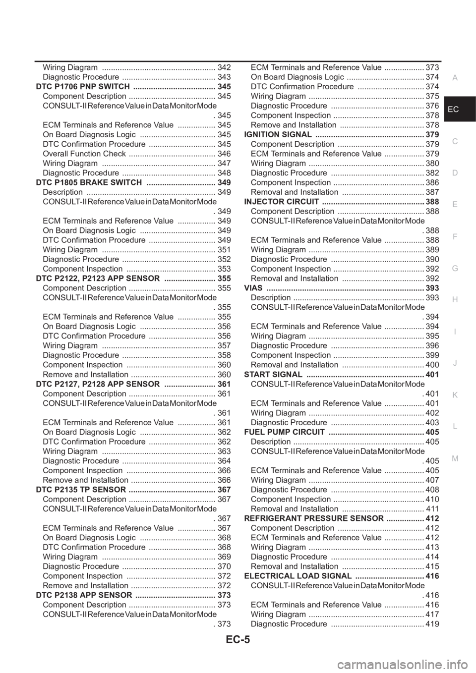
EC-5
C
D
E
F
G
H
I
J
K
L
M
ECA Wiring Diagram .................................................... 342
Diagnostic Procedure ........................................... 343
DTC P1706 PNP SWITCH ...................................... 345
Component Description ........................................ 345
CONSULT-II Reference Value in Data Monitor Mode
. 345
ECM Terminals and Reference Value .................. 345
On Board Diagnosis Logic ................................... 345
DTC Confirmation Procedure ............................... 345
Overall Function Check ........................................ 346
Wiring Diagram .................................................... 347
Diagnostic Procedure ........................................... 348
DTC P1805 BRAKE SWITCH ................................ 349
Description ........................................................... 349
CONSULT-II Reference Value in Data Monitor Mode
. 349
ECM Terminals and Reference Value .................. 349
On Board Diagnosis Logic ................................... 349
DTC Confirmation Procedure ............................... 349
Wiring Diagram .................................................... 351
Diagnostic Procedure ........................................... 352
Component Inspection ......................................... 353
DTC P2122, P2123 APP SENSOR ........................ 355
Component Description ........................................ 355
CONSULT-II Reference Value in Data Monitor Mode
. 355
ECM Terminals and Reference Value .................. 355
On Board Diagnosis Logic ................................... 356
DTC Confirmation Procedure ............................... 356
Wiring Diagram .................................................... 357
Diagnostic Procedure ........................................... 358
Component Inspection ......................................... 360
Remove and Installation ....................................... 360
DTC P2127, P2128 APP SENSOR ........................ 361
Component Description ........................................ 361
CONSULT-II Reference Value in Data Monitor Mode
. 361
ECM Terminals and Reference Value .................. 361
On Board Diagnosis Logic ................................... 362
DTC Confirmation Procedure ............................... 362
Wiring Diagram .................................................... 363
Diagnostic Procedure ........................................... 364
Component Inspection ......................................... 366
Remove and Installation ....................................... 366
DTC P2135 TP SENSOR ........................................ 367
Component Description ........................................ 367
CONSULT-II Reference Value in Data Monitor Mode
. 367
ECM Terminals and Reference Value .................. 367
On Board Diagnosis Logic ................................... 368
DTC Confirmation Procedure ............................... 368
Wiring Diagram ................................................
.... 369
Diagnostic Procedure ........................................... 370
Component Inspection ......................................... 372
Remove and Installation ....................................... 372
DTC P2138 APP SENSOR ..................................... 373
Component Description ........................................ 373
CONSULT-II Reference Value in Data Monitor Mode
. 373ECM Terminals and Reference Value ...................373
On Board Diagnosis Logic ....................................374
DTC Confirmation Procedure ...............................374
Wiring Diagram .....................................................375
Diagnostic Procedure ...........................................376
Component Inspection ..........................................378
Remove and Installation .......................................378
IGNITION SIGNAL ..................................................379
Component Description ........................................379
ECM Terminals and Reference Value ...................379
Wiring Diagram .....................................................380
Diagnostic Procedure ...........................................382
Component Inspection ..........................................386
Removal and Installation ......................................387
INJECTOR CIRCUIT ...............................................388
Component Description ........................................388
CONSULT-II Reference Value in Data Monitor Mode
.388
ECM Terminals and Reference Value ...................388
Wiring Diagram .....................................................389
Diagnostic Procedure ...........................................390
Component Inspection ..........................................392
Removal and Installation ......................................392
VIAS ........................................................................393
Description ............................................................393
CONSULT-II Reference Value in Data Monitor Mode
.394
ECM Terminals and Reference Value ...................394
Wiring Diagram .....................................................395
Diagnostic Procedure ...........................................396
Component Inspection ..........................................399
Removal and Installation ......................................400
START SIGNAL ......................................................401
CONSULT-II Reference Value in Data Monitor Mode
.401
ECM Terminals and Reference Value ...................401
Wiring Diagram .....................................................402
Diagnostic Procedure ...........................................403
FUEL PUMP CIRCUIT ............................................405
Description ............................................................405
CONSULT-II Reference Value in Data Monitor Mode
.405
ECM Terminals and Reference Value ..................
.405
Wiring Diagram .....................................................407
Diagnostic Procedure ...........................................408
Component Inspection ..........................................410
Removal and Installation ......................................411
REFRIGERANT PRESSURE SENSOR ..................412
Component Description ........................................412
ECM Terminals and Reference Value ...................412
Wiring Diagram .....................................................413
Diagnostic Procedure ...........................................414
Removal and Installation ......................................415
ELECTRICAL LOAD SIGNAL ................................416
CONSULT-II Reference Value in Data Monitor Mode
.416
ECM Terminals and Reference Value ...................416
Wiring Diagram .....................................................417
Diagnostic Procedure ...........................................419