service indicator NISSAN X-TRAIL 2001 Service User Guide
[x] Cancel search | Manufacturer: NISSAN, Model Year: 2001, Model line: X-TRAIL, Model: NISSAN X-TRAIL 2001Pages: 3833, PDF Size: 39.49 MB
Page 367 of 3833
EC-17
C
D
E
F
G
H
I
J
K
L
M
ECA INJECTOR CIRCUIT ..............................................1357
Component Description .......................................1357
CONSULT-II Reference Value in Data Monitor Mode
1357
ECM Terminals and Reference Value .................1357
Wiring Diagram ...................................................1358
Diagnostic Procedure ..........................................1359
Component Inspection ........................................1361
Removal and Installation .....................................1361
START SIGNAL .....................................................1362
CONSULT-II Reference Value in Data Monitor Mode
1362
ECM Terminals and Reference Value .................1362
Wiring Diagram ...................................................1363
Diagnostic Procedure ..........................................1364
FUEL PUMP CIRCUIT ...........................................1366
Description ..........................................................1366
CONSULT-II Reference Value in Data Monitor Mode
1366
ECM Terminals and Reference Value .................1366
Wiring Diagram ...................................................1368
Diagnostic Procedure ..........................................1369
Component Inspection ........................................1371
Removal and Installation .....................................1372
REFRIGERANT PRESSURE SENSOR ................1373
Component Description .......................................1373
ECM Terminals and Reference Value .................1373
Wiring Diagram ...................................................1374
Diagnostic Procedure ..........................................1375
Removal and Installation .....................................1376
ELECTRICAL LOAD SIGNAL ...............................1377
CONSULT-II Reference Value in Data Monitor Mode
1377
ECM Terminals and Reference Value .................1377
Wiring Diagram ...................................................1378
Diagnostic Procedure ..........................................1380
DATA LINK CONNECTOR ....................................1385
Wiring Diagram ...................................................1385
EVAPORATIVE EMISSION SYSTEM ....................1386
Description ..........................................................1386
Component Inspection ........................................1388
POSITIVE CRANKCASE VENTILATION ..............1389
Description ..........................................................1389
Component Inspection ........................................1389
SERVICE DATA AND SPECIFICATIONS (SDS) ...1391
Fuel Pressure ......................................................1391
Idle Speed and Ignition Timing ............................1391
Calculated Load Value ........................................1391
Mass Air Flow Sensor .........................................1391
Intake Air Temperature Sensor ...........................1391
Engine Coolant Temperature Sensor ..................1391
Heated Oxygen Sensor 1 Heater ........................1391
Heated Oxygen sensor 2 Heater .........................1391
Crankshaft Position Sensor (POS) ......................1391
Camshaft Position Sensor (PHASE) ...................1391
Throttle Control Motor ......................................... 1392
Injector ................................................................1392
Fuel Pump ...........................................................1392
YD
INDEX FOR DTC ....................................................1393
Alphabetical Index ...............................................1393
DTC No. Index .....................................................1393
PRECAUTIONS .....................................................1395
Precautions for Supplemental Restraint System
(SRS) “AIR BAG” and “SEAT BELT PRE-TEN-
SIONER” ..............................................................1395
Precautions ..........................................................1395
Wiring Diagrams and Trouble Diagnosis .............1397
ENGINE CONTROL SYSTEM ...............................1398
System Diagram ..................................................1398
System Chart .......................................................1399
Fuel Injection Control System ..............................1399
Fuel Injection Timing Control System ..................1401
Air Conditioning Cut Control ................................1401
F u e l C u t C o n t r o l ( A t N o L o a d & H i g h E n g i n e S p e e d ) 1401
Crankcase Ventilation System .............................1402
CAN Communication ...........................................1402
BASIC SERVICE PROCEDURE ............................1404
Fuel Filter .............................................................1404
Accelerator Pedal Released Position Learning ...1404
Fuel Pressure Relief Valve ..................................1405
ON BOARD DIAGNOSTIC (OBD) SYSTEM .........1406
DTC and MI Detection Logic ...............................1406
Diagnostic Trouble Code (DTC) ..........................1406
NATS (Nissan Anti-theft System) ........................1406
Malfunction Indicator (MI) ....................................1407
TROUBLE DIAGNOSIS .........................................1409
Trouble Diagnosis Introduction ............................1409
Basic Inspection ..................................................1412
Symptom Matrix Chart .........................................1416
Engine Control Component Parts Location .........1420
Circuit Diagram ....................................................1423
ECM Harness Connector Terminal Layout ..........1425
ECM Terminals And Reference Value .................1425
CONSULT-II Function ..........................................1431
CONSULT-II Reference Value in Data Monitor Mode
1437
Major Sensor Reference Graph in Data Monitor
Mode ....................................................................1440
TROUBLE DIAGNOSIS FOR INTERMITTENT INCI-
DENT ......................................................................1441
Description ...........................................................1441
Diagnostic Procedure ..........................................1441
POWER SUPPLY CIRCUIT FOR ECM ..................1442
ECM Terminals and Reference Value ..................1442
Wiring Diagram ....................................................1443
Diagnostic Procedure ..........................................1444
Component Inspection .........................................1447
DTC U1000 CAN COMMUNICATION LINE ...........1448
Description ...........................................................1448
On Board Diagnosis Logic ...................................1448
DTC Confirmation Procedure ..............................1448
Wiring Diagram ....................................................1449
Diagnostic Procedure ..........................................1450
DTC P0100 MASS AIR FLOW SENSOR (MAFS) .1451
Component Description .......................................1451
Page 375 of 3833

PRECAUTIONS
EC-25
[QR25(WITH EURO-OBD)]
C
D
E
F
G
H
I
J
K
L
MA
EC
PRECAUTIONSPFP:00001
Precautions for Supplemental Restraint System (SRS) “AIR BAG” and “SEAT
BELT PRE-TENSIONER”
EBS00NBQ
The Supplemental Restraint System such as “AIR BAG” and “SEAT BELT PRE-TENSIONER”, used along
with a front seat belt, helps to reduce the risk or severity of injury to the driver and front passenger for certain
types of collision. Information necessary to service the system safely is included in the SRS and SB section of
this Service Manual.
WARNING:
●To avoid rendering the SRS inoperative, which could increase the risk of personal injury or death
in the event of a collision which would result in air bag inflation, all maintenance must be per-
formed by an authorized NISSAN/INFINITI dealer.
●Improper maintenance, including incorrect removal and installation of the SRS, can lead to per-
sonal injury caused by unintentional activation of the system. For removal of Spiral Cable and Air
Bag Module, see the SRS section.
●Do not use electrical test equipment on any circuit related to the SRS unless instructed to in this
Service Manual. SRS wiring harnesses can be identified by yellow and/or orange harness connec-
tors.
On Board Diagnostic (OBD) System of Engine and A/TEBS00M04
The ECM has an on board diagnostic system. It will light up the malfunction indicator (MI) to warn the driver of
a malfunction causing emission deterioration.
CAUTION:
●Be sure to turn the ignition switch OFF and disconnect the negative battery terminal before any
repair or inspection work. The open/short circuit of related switches, sensors, solenoid valves,
etc. will cause the MI to light up.
●Be sure to connect and lock the connectors securely after work. A loose (unlocked) connector will
cause the MI to light up due to the open circuit. (Be sure the connector is free from water, grease,
dirt, bent terminals, etc.)
●Certain systems and components, especially those related to OBD, may use a new style slide-
locking type harness connector. For description and how to disconnect, refer to PG-68, "
HAR-
NESS CONNECTOR" .
●Be sure to route and secure the harnesses properly after work. The interference of the harness
with a bracket, etc. may cause the MI to light up due to the short circuit.
●Be sure to connect rubber tubes properly after work. A misconnected or disconnected rubber tube
may cause the MI to light up due to the malfunction of the fuel injection system, etc.
●Be sure to erase the unnecessary malfunction information (repairs completed) from the ECM and
TCM (Transmission control module) before returning the vehicle to the customer.
PrecautionEBS00M05
●Always use a 12 volt battery as power source.
●Do not attempt to disconnect battery cables while engine is
running.
●Before connecting or disconnecting the ECM harness con-
nector, turn ignition switch OFF and disconnect negative
battery terminal. Failure to do so may damage the ECM
because battery voltage is applied to ECM even if ignition
switch is turned off.
●Before removing parts, turn ignition switch OFF and then
disconnect battery ground cable.
SEF289H
Page 423 of 3833

TROUBLE DIAGNOSIS
EC-73
[QR25(WITH EURO-OBD)]
C
D
E
F
G
H
I
J
K
L
MA
EC
Basic InspectionEBS00M0V
1.INSPECTION START
1. Check service records for any recent repairs that may indicate a related incident, or a current need for
scheduled maintenance.
2. Open engine hood and check the following:
–Harness connectors for improper connections
–Wiring harness for improper connections, pinches and cut
–Vacuum hoses for splits, kinks and improper connections
–Hoses and ducts for leaks
–Air cleaner clogging
–Gasket
3. Confirm that electrical or mechanical loads are not applied.
–Headlamp switch is OFF.
–Air conditioner switch is OFF.
–Rear window defogger switch is OFF.
–Steering wheel is in the straight-ahead position, etc.
4. Start engine and warm it up until engine coolant temperature
indicator points the middle of gauge.
Ensure engine stays below 1,000 rpm.
5. Run engine at about 2,000 rpm for about 2 minutes under no-
load.
6. Make sure that no DTC is displayed with CONSULT-II or GST.
OK or NG
OK >> GO TO 3.
NG >> GO TO 2.
2.REPAIR OR REPLACE
Repair or replace components as necessary according to corresponding “Diagnostic Procedure”.
>> GO TO 3
SEF983U
SEF976U
SEF977U
Page 785 of 3833

PRECAUTIONS
EC-435
[QR25(WITHOUT EURO-OBD)]
C
D
E
F
G
H
I
J
K
L
MA
EC
PRECAUTIONSPFP:00001
Precautions for Supplemental Restraint System (SRS) “AIR BAG” and “SEAT
BELT PRE-TENSIONER”
EBS00NDL
The Supplemental Restraint System such as “AIR BAG” and “SEAT BELT PRE-TENSIONER”, used along
with a front seat belt, helps to reduce the risk or severity of injury to the driver and front passenger for certain
types of collision. Information necessary to service the system safely is included in the SRS and SB section of
this Service Manual.
WARNING:
●To avoid rendering the SRS inoperative, which could increase the risk of personal injury or death
in the event of a collision which would result in air bag inflation, all maintenance must be per-
formed by an authorized NISSAN/INFINITI dealer.
●Improper maintenance, including incorrect removal and installation of the SRS, can lead to per-
sonal injury caused by unintentional activation of the system. For removal of Spiral Cable and Air
Bag Module, see the SRS section.
●Do not use electrical test equipment on any circuit related to the SRS unless instructed to in this
Service Manual. SRS wiring harnesses can be identified by yellow and/or orange harness connec-
tors.
On Board Diagnostic (OBD) System of Engine and A/TEBS00NDM
The ECM has an on board diagnostic system. It will light up the malfunction indicator (MI) to warn the driver of
a malfunction causing emission deterioration.
CAUTION:
●Be sure to turn the ignition switch OFF and disconnect the negative battery terminal before any
repair or inspection work. The open/short circuit of related switches, sensors, solenoid valves,
etc. will cause the MI to light up.
●Be sure to connect and lock the connectors securely after work. A loose (unlocked) connector will
cause the MI to light up due to the open circuit. (Be sure the connector is free from water, grease,
dirt, bent terminals, etc.)
●Certain systems and components, especially those related to OBD, may use a new style slide-
locking type harness connector. For description and how to disconnect, refer to PG-68, "
HAR-
NESS CONNECTOR" .
●Be sure to route and secure the harnesses properly after work. The interference of the harness
with a bracket, etc. may cause the MI to light up due to the short circuit.
●Be sure to connect rubber tubes properly after work. A misconnected or disconnected rubber tube
may cause the MI to light up due to the malfunction of the fuel injection system, etc.
●Be sure to erase the unnecessary malfunction information (repairs completed) from the ECM and
TCM (Transmission control module) before returning the vehicle to the customer.
PrecautionEBS00NDN
●Always use a 12 volt battery as power source.
●Do not attempt to disconnect battery cables while engine is
running.
●Before connecting or disconnecting the ECM harness con-
nector, turn ignition switch OFF and disconnect negative
battery terminal. Failure to do so may damage the ECM
because battery voltage is applied to ECM even if ignition
switch is turned off.
●Before removing parts, turn ignition switch OFF and then
disconnect battery ground cable.
SEF289H
Page 815 of 3833

TROUBLE DIAGNOSIS
EC-465
[QR25(WITHOUT EURO-OBD)]
C
D
E
F
G
H
I
J
K
L
MA
EC
Basic InspectionEBS00NEC
1.INSPECTION START
1. Check service records for any recent repairs that may indicate a related incident, or a current need for
scheduled maintenance.
2. Open engine hood and check the following:
–Harness connectors for improper connections
–Wiring harness for improper connections, pinches and cut
–Vacuum hoses for splits, kinks and improper connections
–Hoses and ducts for leaks
–Air cleaner clogging
–Gasket
3. Confirm that electrical or mechanical loads are not applied.
–Headlamp switch is OFF.
–Air conditioner switch is OFF.
–Rear window defogger switch is OFF.
–Steering wheel is in the straight-ahead position, etc.
4. Start engine and warm it up until engine coolant temperature
indicator points the middle of gauge.
Ensure engine stays below 1,000 rpm.
5. Run engine at about 2,000 rpm for about 2 minutes under no-
load.
6. Make sure that no DTC is displayed with CONSULT-II or GST.
OK or NG
OK >> GO TO 3.
NG >> GO TO 2.
2.REPAIR OR REPLACE
Repair or replace components as necessary according to corresponding “Diagnostic Procedure”.
>> GO TO 3.
P1229 Sensor power supply ECM stops the electric throttle control actuator control, throttle valve is maintained at a
fixed opening (approx. 5 degrees) by the return spring.
P2122
P2123
P2127
P2128
P2138Accelerator pedal position
sensorThe ECM controls the electric throttle control actuator in regulating the throttle opening
in order for the idle position to be within +10 degrees.
The ECM regulates the opening speed of the throttle valve to be slower than the nor-
mal condition.
So, the acceleration will be poor. DTC No. Detected items Engine operating condition in fail-safe mode
SEF983U
SEF976U
SEF977U
Page 1107 of 3833

PRECAUTIONS
EC-757
[QR20(WITH EURO-OBD)]
C
D
E
F
G
H
I
J
K
L
MA
EC
PRECAUTIONSPFP:00001
Precautions for Supplemental Restraint System (SRS) “AIR BAG” and “SEAT
BELT PRE-TENSIONER”
EBS00NBR
The Supplemental Restraint System such as “AIR BAG” and “SEAT BELT PRE-TENSIONER”, used along
with a front seat belt, helps to reduce the risk or severity of injury to the driver and front passenger for certain
types of collision. Information necessary to service the system safely is included in the SRS and SB section of
this Service Manual.
WARNING:
●To avoid rendering the SRS inoperative, which could increase the risk of personal injury or death
in the event of a collision which would result in air bag inflation, all maintenance must be per-
formed by an authorized NISSAN/INFINITI dealer.
●Improper maintenance, including incorrect removal and installation of the SRS, can lead to per-
sonal injury caused by unintentional activation of the system. For removal of Spiral Cable and Air
Bag Module, see the SRS section.
●Do not use electrical test equipment on any circuit related to the SRS unless instructed to in this
Service Manual. SRS wiring harnesses can be identified by yellow and/or orange harness connec-
tors.
On Board Diagnostic (OBD) System of Engine and A/TEBS00MS3
The ECM has an on board diagnostic system. It will light up the malfunction indicator (MI) to warn the driver of
a malfunction causing emission deterioration.
CAUTION:
●Be sure to turn the ignition switch OFF and disconnect the negative battery terminal before any
repair or inspection work. The open/short circuit of related switches, sensors, solenoid valves,
etc. will cause the MI to light up.
●Be sure to connect and lock the connectors securely after work. A loose (unlocked) connector will
cause the MI to light up due to the open circuit. (Be sure the connector is free from water, grease,
dirt, bent terminals, etc.)
●Certain systems and components, especially those related to OBD, may use a new style slide-
locking type harness connector. For description and how to disconnect, refer to PG-68, "
HAR-
NESS CONNECTOR" .
●Be sure to route and secure the harnesses properly after work. The interference of the harness
with a bracket, etc. may cause the MI to light up due to the short circuit.
●Be sure to connect rubber tubes properly after work. A misconnected or disconnected rubber tube
may cause the MI to light up due to the malfunction of the fuel injection system, etc.
●Be sure to erase the unnecessary malfunction information (repairs completed) from the ECM and
TCM (Transmission control module) before returning the vehicle to the customer.
PrecautionEBS00MS4
●Always use a 12 volt battery as power source.
●Do not attempt to disconnect battery cables while engine is
running.
●Before connecting or disconnecting the ECM harness con-
nector, turn ignition switch OFF and disconnect negative
battery terminal. Failure to do so may damage the ECM
because battery voltage is applied to ECM even if ignition
switch is turned off.
●Before removing parts, turn ignition switch OFF and then
disconnect battery ground cable.
SEF289H
Page 1155 of 3833

TROUBLE DIAGNOSIS
EC-805
[QR20(WITH EURO-OBD)]
C
D
E
F
G
H
I
J
K
L
MA
EC
Basic InspectionEBS00MSU
1.INSPECTION START
1. Check service records for any recent repairs that may indicate a related incident, or a current need for
scheduled maintenance.
2. Open engine hood and check the following:
–Harness connectors for improper connections
–Wiring harness for improper connections, pinches and cut
–Vacuum hoses for splits, kinks and improper connections
–Hoses and ducts for leaks
–Air cleaner clogging
–Gasket
3. Confirm that electrical or mechanical loads are not applied.
–Headlamp switch is OFF.
–Air conditioner switch is OFF.
–Rear window defogger switch is OFF.
–Steering wheel is in the straight-ahead position, etc.
4. Start engine and warm it up until engine coolant temperature
indicator points the middle of gauge.
Ensure engine stays below 1,000 rpm.
5. Run engine at about 2,000 rpm for about 2 minutes under no-
load.
6. Make sure that no DTC is displayed with CONSULT-II or GST.
OK or NG
OK >> GO TO 3.
NG >> GO TO 2.
2.REPAIR OR REPLACE
Repair or replace components as necessary according to corresponding “Diagnostic Procedure”.
>> GO TO 3
SEF983U
SEF976U
SEF977U
Page 1471 of 3833

PRECAUTIONS
EC-1121
[QR20(WITHOUT EURO-OBD)]
C
D
E
F
G
H
I
J
K
L
MA
EC
PRECAUTIONSPFP:00001
Precautions for Supplemental Restraint System (SRS) “AIR BAG” and “SEAT
BELT PRE-TENSIONER”
EBS00NBS
The Supplemental Restraint System such as “AIR BAG” and “SEAT BELT PRE-TENSIONER”, used along
with a front seat belt, helps to reduce the risk or severity of injury to the driver and front passenger for certain
types of collision. Information necessary to service the system safely is included in the SRS and SB section of
this Service Manual.
WARNING:
●To avoid rendering the SRS inoperative, which could increase the risk of personal injury or death
in the event of a collision which would result in air bag inflation, all maintenance must be per-
formed by an authorized NISSAN/INFINITI dealer.
●Improper maintenance, including incorrect removal and installation of the SRS, can lead to per-
sonal injury caused by unintentional activation of the system. For removal of Spiral Cable and Air
Bag Module, see the SRS section.
●Do not use electrical test equipment on any circuit related to the SRS unless instructed to in this
Service Manual. SRS wiring harnesses can be identified by yellow and/or orange harness connec-
tors.
On Board Diagnostic (OBD) System of Engine and A/TEBS00N39
The ECM has an on board diagnostic system. It will light up the malfunction indicator (MI) to warn the driver of
a malfunction causing emission deterioration.
CAUTION:
●Be sure to turn the ignition switch OFF and disconnect the negative battery terminal before any
repair or inspection work. The open/short circuit of related switches, sensors, solenoid valves,
etc. will cause the MI to light up.
●Be sure to connect and lock the connectors securely after work. A loose (unlocked) connector will
cause the MI to light up due to the open circuit. (Be sure the connector is free from water, grease,
dirt, bent terminals, etc.)
●Certain systems and components, especially those related to OBD, may use a new style slide-
locking type harness connector. For description and how to disconnect, refer to PG-68, "
HAR-
NESS CONNECTOR" .
●Be sure to route and secure the harnesses properly after work. The interference of the harness
with a bracket, etc. may cause the MI to light up due to the short circuit.
●Be sure to connect rubber tubes properly after work. A misconnected or disconnected rubber tube
may cause the MI to light up due to the malfunction of the fuel injection system, etc.
●Be sure to erase the unnecessary malfunction information (repairs completed) from the ECM and
TCM (Transmission control module) before returning the vehicle to the customer.
PrecautionEBS00N3A
●Always use a 12 volt battery as power source.
●Do not attempt to disconnect battery cables while engine is
running.
●Before connecting or disconnecting the ECM harness con-
nector, turn ignition switch OFF and disconnect negative
battery terminal. Failure to do so may damage the ECM
because battery voltage is applied to ECM even if ignition
switch is turned off.
●Before removing parts, turn ignition switch OFF and then
disconnect battery ground cable.
SEF289H
Page 1502 of 3833

EC-1152
[QR20(WITHOUT EURO-OBD)]
TROUBLE DIAGNOSIS
Basic Inspection
EBS00N3Z
1. INSPECTION START
1. Check service records for any recent repairs that may indicate a related incident, or a current need for
scheduled maintenance.
2. Open engine hood and check the following:
–Harness connectors for improper connections
–Wiring harness for improper connections, pinches and cut
–Vacuum hoses for splits, kinks and improper connections
–Hoses and ducts for leaks
–Air cleaner clogging
–Gasket
3. Confirm that electrical or mechanical loads are not applied.
–Headlamp switch is OFF.
–Air conditioner switch is OFF.
–Rear window defogger switch is OFF.
–Steering wheel is in the straight-ahead position, etc.
4. Start engine and warm it up until engine coolant temperature
indicator points the middle of gauge.
Ensure engine stays below 1,000 rpm.
5. Run engine at about 2,000 rpm for about 2 minutes under no-
load.
6. Make sure that no DTC is displayed with CONSULT-II or GST.
OK or NG
OK >> GO TO 3.
NG >> GO TO 2.
2. REPAIR OR REPLACE
Repair or replace components as necessary according to corresponding “Diagnostic Procedure”.
>> GO TO 3.
SEF983U
SEF976U
SEF977U
Page 2069 of 3833
FINAL DRIVE
MT-93
D
E
F
G
H
I
J
K
L
MA
B
MT
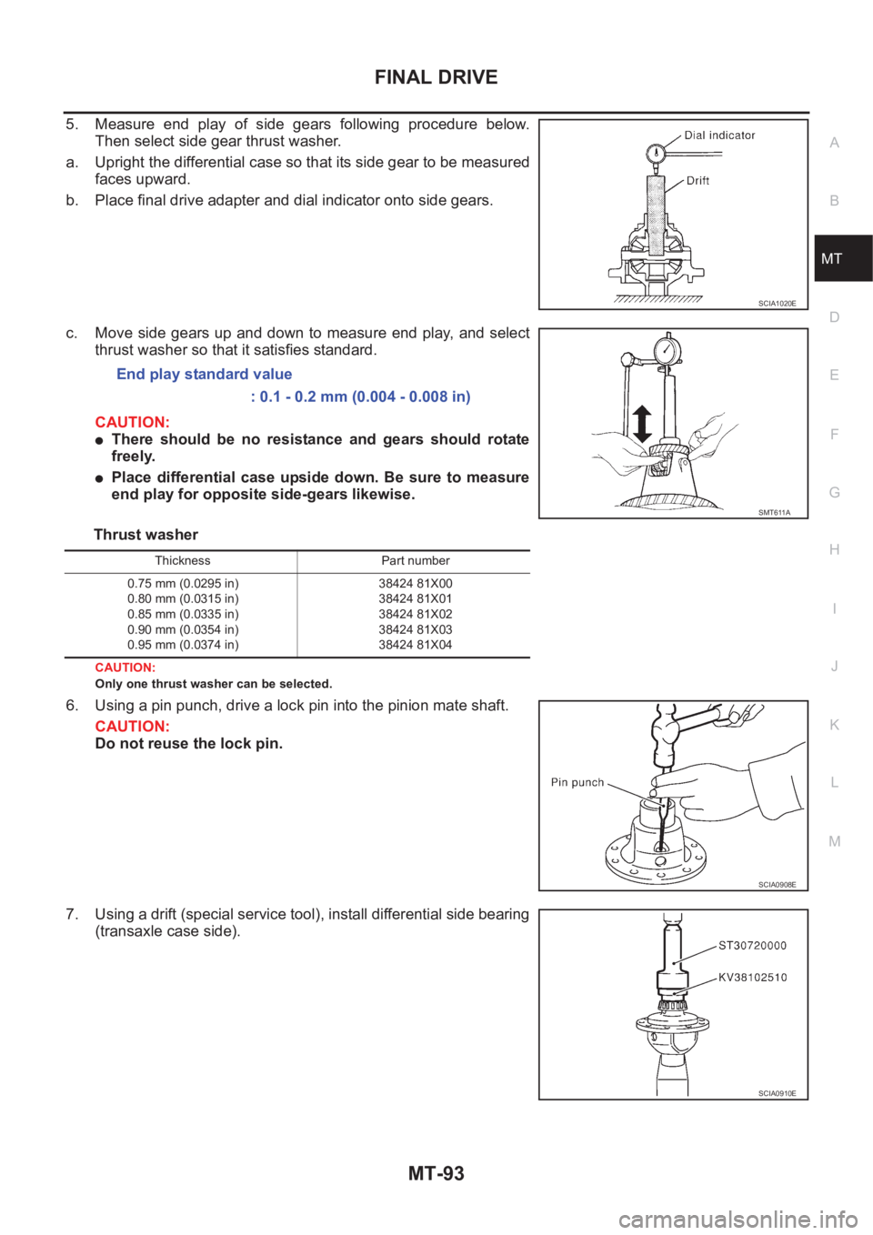
5. Measure end play of side gears following procedure below.
Then select side gear thrust washer.
a. Upright the differential case so that its side gear to be measured
faces upward.
b. Place final drive adapter and dial indicator onto side gears.
c. Move side gears up and down to measure end play, and select
thrust washer so that it satisfies standard.
CAUTION:
●There should be no resistance and gears should rotate
freely.
●Place differential case upside down. Be sure to measure
end play for opposite side-gears likewise.
Thrust washer
CAUTION:
Only one thrust washer can be selected.
6. Using a pin punch, drive a lock pin into the pinion mate shaft.
CAUTION:
Do not reuse the lock pin.
7. Using a drift (special service tool), install differential side bearing
(transaxle case side).
SCIA1020E
End play standard value
: 0.1 - 0.2 mm (0.004 - 0.008 in)
SMT611A
Thickness Part number
0.75 mm (0.0295 in)
0.80 mm (0.0315 in)
0.85 mm (0.0335 in)
0.90 mm (0.0354 in)
0.95 mm (0.0374 in)38424 81X00
38424 81X01
38424 81X02
38424 81X03
38424 81X04
SCIA0908E
SCIA0910E