battery NISSAN X-TRAIL 2001 Service Repair Manual
[x] Cancel search | Manufacturer: NISSAN, Model Year: 2001, Model line: X-TRAIL, Model: NISSAN X-TRAIL 2001Pages: 3833, PDF Size: 39.49 MB
Page 3 of 3833
GI-1
GENERAL INFORMATION
A GENERAL INFORMATION
CONTENTS
C
D
E
F
G
H
I
J
K
L
MB
GI
SECTION
GENERAL INFORMATION
PRECAUTIONS .......................................................... 3
Description ............................................................... 3
Precautions for Supplemental Restraint System
(SRS) “AIR BAG” and “SEAT BELT PRE-TEN-
SIONER” .................................................................. 3
Precautions for NATS (NISSAN ANTI-THEFT SYS-
TEM) ........................................................................ 3
General Precautions ................................................ 4
Precautions for All Mode 4 × 4 System .................... 5
Precautions for Three Way Catalyst ......................... 5
Precautions for Fuel ................................................. 5
GASOLINE ENGINE ............................................. 5
DIESEL ENGINE ................................................... 5
Precautions for Multiport Fuel Injection System or
Engine Control System ............................................ 6
Precautions for Turbocharger (If Equipped) ............. 6
Precautions for Hoses .............................................. 6
HOSE REMOVAL AND INSTALLATION ............... 6
HOSE CLAMPING ................................................ 7
Precautions for Engine Oils ...................................... 7
HEALTH PROTECTION PRECAUTIONS ............. 7
ENVIRONMENTAL PROTECTION PRECAU-
TIONS ................................................................... 7
Precautions for Air Conditioning ............................... 7
HOW TO USE THIS MANUAL ................................... 8
Description ............................................................... 8
Terms ....................................................................... 8
Units ......................................................................... 8
Contents ................................................................... 8
Components ............................................................. 8
SYMBOLS ............................................................. 9
How to Follow Trouble Diagnoses ............................ 9
DESCRIPTION ...................................................... 9
HOW TO FOLLOW TEST GROUPS IN TROU-
BLE DIAGNOSES ............................................... 10
HARNESS WIRE COLOR AND CONNECTOR
NUMBER INDICATION ........................................ 11
KEY TO SYMBOLS SIGNIFYING MEASURE-
MENTS OR PROCEDURES ............................... 12
How to Read Wiring Diagrams ............................... 14CONNECTOR SYMBOLS ................................... 14
SAMPLE/WIRING DIAGRAM - EXAMPL - .......... 15
DESCRIPTION .................................................... 16
Abbreviations .......................................................... 22
SERVICE INFORMATION FOR ELECTRICAL INCI-
DENT ......................................................................... 23
How to Perform Efficient Diagnosis for an Electrical
Incident ................................................................... 23
WORK FLOW ...................................................... 23
INCIDENT SIMULATION TESTS ........................ 23
CIRCUIT INSPECTION ....................................... 26
Control Units and Electrical Parts ........................
... 31
PRECAUTIONS .................................................. 31
CONSULT-II CHECKING SYSTEM .......................... 33
Description .............................................................. 33
Function and System Application ........................... 33
Nickel Metal Hydride Battery Replacement ............ 33
Checking Equipment .............................................. 34
CONSULT-II Data Link Connector (DLC) Circuit .... 34
INSPECTION PROCEDURE .............................. 34
LIFTING POINT ......................................................... 35
Special Service Tools ............................................. 35
Garage Jack and Safety Stand ............................... 35
2-pole Lift ................................................................ 36
Board-on Lift ........................................................... 37
TOW TRUCK TOWING ............................................. 38
Tow Truck Towing ................................................... 38
TOWING AN AUTOMATIC TRANSAXLE
MODEL WITH FOUR WHEELS ON GROUND ... 38
T O W I N G T H E V E H I C L E W I T H R E A R W H E E L S
R A I S E D ( W I T H F R O N T W H E E L S O N G R O U N D )
OR FRONT WHEELS RAISED ........................... 39
Vehicle Recovery (Freeing a stuck vehicle) ............ 39
TIGHTENING TORQUE OF STANDARD BOLTS .... 40
Tightening Torque Table ......................................... 40
IDENTIFICATION INFORMATION ............................ 41
Model Variation ....................................................... 41
IDENTIFICATION NUMBER ................................ 42
IDENTIFICATION PLATE .................................... 43
ENGINE SERIAL NUMBER ................................ 43
Page 8 of 3833
GI-6
PRECAUTIONS
CAUTION:
●Do not use home heating oil, gasoline or other alternate fuels in your diesel engine. The use of
those can cause engine damage.
●Do not use summer fuel at temperatures below –7°C (20°F). The cold temperatures will cause wax
to form in the fuel. As a result, it may prevent the engine from running smoothly.
●Do not add gasoline or other alternate fuels to diesel fuel.
Precautions for Multiport Fuel Injection System or Engine Control SystemEAS000FT
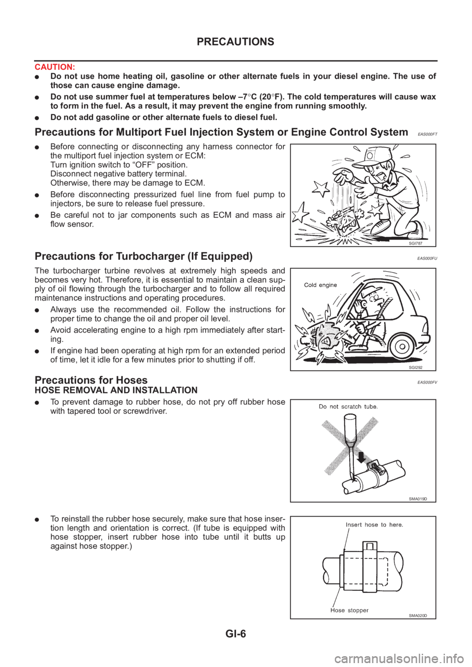
●Before connecting or disconnecting any harness connector for
the multiport fuel injection system or ECM:
Turn ignition switch to “OFF” position.
Disconnect negative battery terminal.
Otherwise, there may be damage to ECM.
●Before disconnecting pressurized fuel line from fuel pump to
injectors, be sure to release fuel pressure.
●Be careful not to jar components such as ECM and mass air
flow sensor.
Precautions for Turbocharger (If Equipped)EAS000FU
The turbocharger turbine revolves at extremely high speeds and
becomes very hot. Therefore, it is essential to maintain a clean sup-
ply of oil flowing through the turbocharger and to follow all required
maintenance instructions and operating procedures.
●Always use the recommended oil. Follow the instructions for
proper time to change the oil and proper oil level.
●Avoid accelerating engine to a high rpm immediately after start-
ing.
●If engine had been operating at high rpm for an extended period
of time, let it idle for a few minutes prior to shutting if off.
Precautions for HosesEAS000FV
HOSE REMOVAL AND INSTALLATION
●To prevent damage to rubber hose, do not pry off rubber hose
with tapered tool or screwdriver.
●To reinstall the rubber hose securely, make sure that hose inser-
tion length and orientation is correct. (If tube is equipped with
hose stopper, insert rubber hose into tube until it butts up
against hose stopper.)
SGI787
SGI292
SMA019D
SMA020D
Page 12 of 3833
GI-10
HOW TO USE THIS MANUAL
1.Before performing trouble diagnoses, read the “Preliminary Check”, the “Symptom Chart” or the
“Work Flow”.
2.After repairs, re-check that the problem has been completely eliminated.
3.Refer to Component Parts and Harness Connector Location for the Systems described in each
section for identification/location of components and harness connectors.
4.Refer to the Circuit Diagram for quick pinpoint check.
If you need to check circuit continuity between harness connectors in more detail, such as when a
sub-harness is used, refer to Wiring Diagram in each individual section and Harness Layout in PG
section for identification of harness connectors.
5.When checking circuit continuity, ignition switch should be OFF.
6.Before checking voltage at connectors, check battery voltage.
7.After accomplishing the Diagnostic Procedures and Electrical Components Inspection, make sure
that all harness connectors are reconnected as they were.
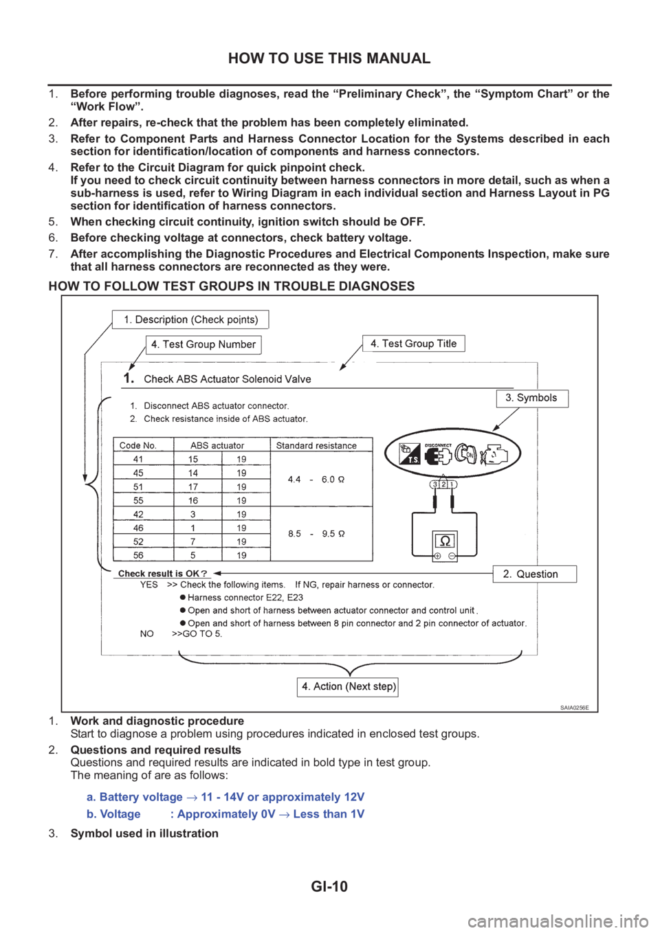
HOW TO FOLLOW TEST GROUPS IN TROUBLE DIAGNOSES
1.Work and diagnostic procedure
Start to diagnose a problem using procedures indicated in enclosed test groups.
2.Questions and required results
Questions and required results are indicated in bold type in test group.
The meaning of are as follows:
3.Symbol used in illustration
SAIA0256E
a. Battery voltage → 11 - 14V or approximately 12V
b. Voltage : Approximately 0V → Less than 1V
Page 14 of 3833
GI-12
HOW TO USE THIS MANUAL
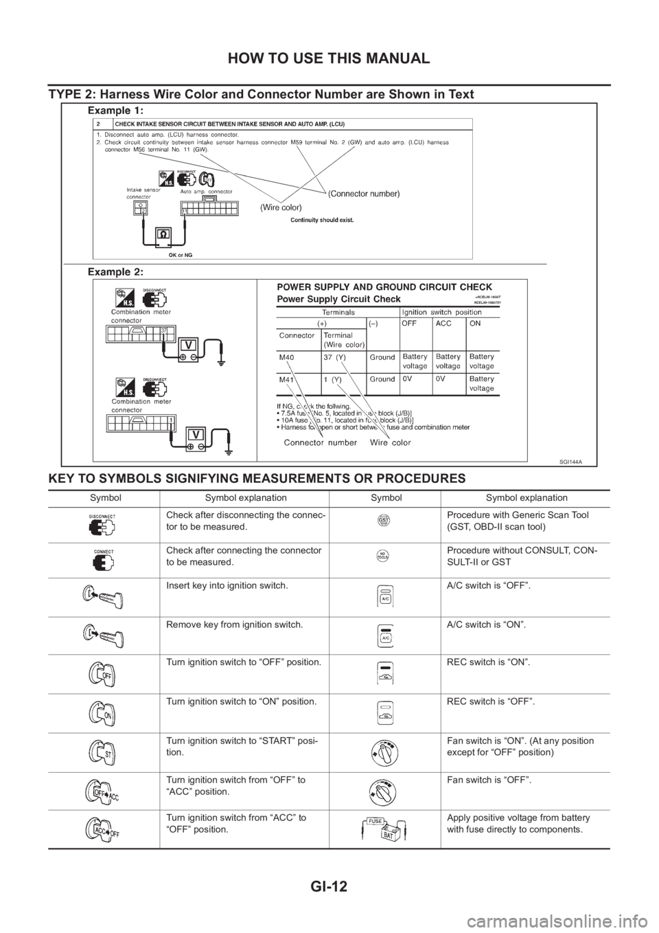
TYPE 2: Harness Wire Color and Connector Number are Shown in Text
KEY TO SYMBOLS SIGNIFYING MEASUREMENTS OR PROCEDURES
SGI144A
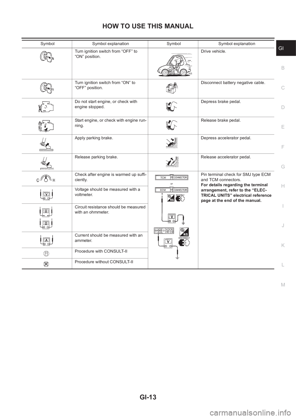
Symbol Symbol explanation Symbol Symbol explanation
Check after disconnecting the connec-
tor to be measured.Procedure with Generic Scan Tool
(GST, OBD-II scan tool)
Check after connecting the connector
to be measured.Procedure without CONSULT, CON-
SULT-II or GST
Insert key into ignition switch. A/C switch is “OFF”.
Remove key from ignition switch. A/C switch is “ON”.
Turn ignition switch to “OFF” position. REC switch is “ON”.
Turn ignition switch to “ON” position. REC switch is “OFF”.
Turn ignition switch to “START” posi-
tion.Fan switch is “ON”. (At any position
except for “OFF” position)
Turn ignition switch from “OFF” to
“ACC” position.Fan switch is “OFF”.
Turn ignition switch from “ACC” to
“OFF” position.Apply positive voltage from battery
with fuse directly to components.
Page 15 of 3833
HOW TO USE THIS MANUAL
GI-13
C
D
E
F
G
H
I
J
K
L
MB
GITurn ignition switch from “OFF” to
“ON” position.Drive vehicle.
Turn ignition switch from “ON” to
“OFF” position.Disconnect battery negative cable.
Do not start engine, or check with
engine stopped.Depress brake pedal.
Start engine, or check with engine run-
ning.Release brake pedal.
Apply parking brake. Depress accelerator pedal.
Release parking brake. Release accelerator pedal.
Check after engine is warmed up suffi-
ciently.Pin terminal check for SMJ type ECM
and TCM connectors.
For details regarding the terminal
arrangement, refer to the “ELEC-
TRICAL UNITS” electrical reference
page at the end of the manual. Voltage should be measured with a
voltmeter.
Circuit resistance should be measured
with an ohmmeter.
Current should be measured with an
ammeter.
Procedure with CONSULT-II
Procedure without CONSULT-II Symbol Symbol explanation Symbol Symbol explanation
Page 18 of 3833
GI-16
HOW TO USE THIS MANUAL
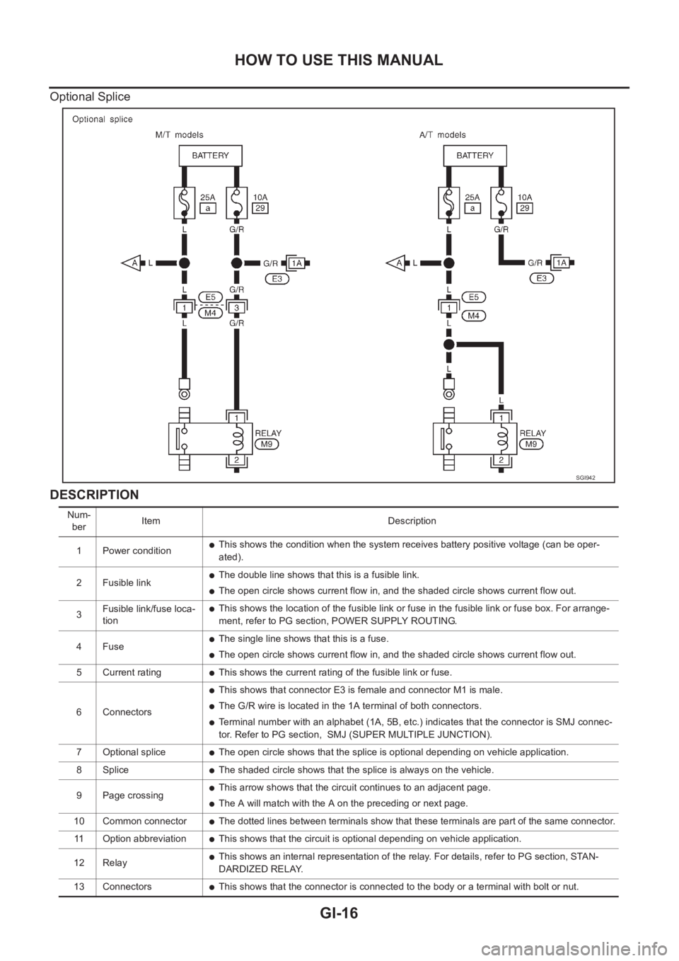
Optional Splice
DESCRIPTION
SGI942
Num-
berItem Description
1 Power condition
●This shows the condition when the system receives battery positive voltage (can be oper-
ated).
2 Fusible link
●The double line shows that this is a fusible link.
●The open circle shows current flow in, and the shaded circle shows current flow out.
3Fusible link/fuse loca-
tion
●This shows the location of the fusible link or fuse in the fusible link or fuse box. For arrange-
ment, refer to PG section, POWER SUPPLY ROUTING.
4Fuse
●The single line shows that this is a fuse.
●The open circle shows current flow in, and the shaded circle shows current flow out.
5 Current rating
●This shows the current rating of the fusible link or fuse.
6 Connectors
●This shows that connector E3 is female and connector M1 is male.
●The G/R wire is located in the 1A terminal of both connectors.
●Terminal number with an alphabet (1A, 5B, etc.) indicates that the connector is SMJ connec-
tor. Refer to PG section, SMJ (SUPER MULTIPLE JUNCTION).
7 Optional splice
●The open circle shows that the splice is optional depending on vehicle application.
8 Splice
●The shaded circle shows that the splice is always on the vehicle.
9 Page crossing
●This arrow shows that the circuit continues to an adjacent page.
●The A will match with the A on the preceding or next page.
10 Common connector
●The dotted lines between terminals show that these terminals are part of the same connector.
11 Option abbreviation
●This shows that the circuit is optional depending on vehicle application.
12 Relay
●This shows an internal representation of the relay. For details, refer to PG section, STAN-
DARDIZED RELAY.
13 Connectors
●This shows that the connector is connected to the body or a terminal with bolt or nut.
Page 28 of 3833
GI-26
SERVICE INFORMATION FOR ELECTRICAL INCIDENT
Cold or Hot Start Up
On some occasions an electrical incident may occur only when the car is started cold, or it may occur when
the car is restarted hot shortly after being turned off. In these cases you may have to keep the car overnight to
make a proper diagnosis.
CIRCUIT INSPECTION
Introduction
In general, testing electrical circuits is an easy task if it is approached in a logical and organized method.
Before beginning it is important to have all available information on the system to be tested. Also, get a thor-
ough understanding of system operation. Then you will be able to use the appropriate equipment and follow
the correct test procedure.
You may have to simulate vehicle vibrations while testing electrical components. Gently shake the wiring har-
ness or electrical component to do this.
NOTE:
Refer to “How to Check Terminal” to probe or check terminal.
Testing for “Opens” in the Circuit
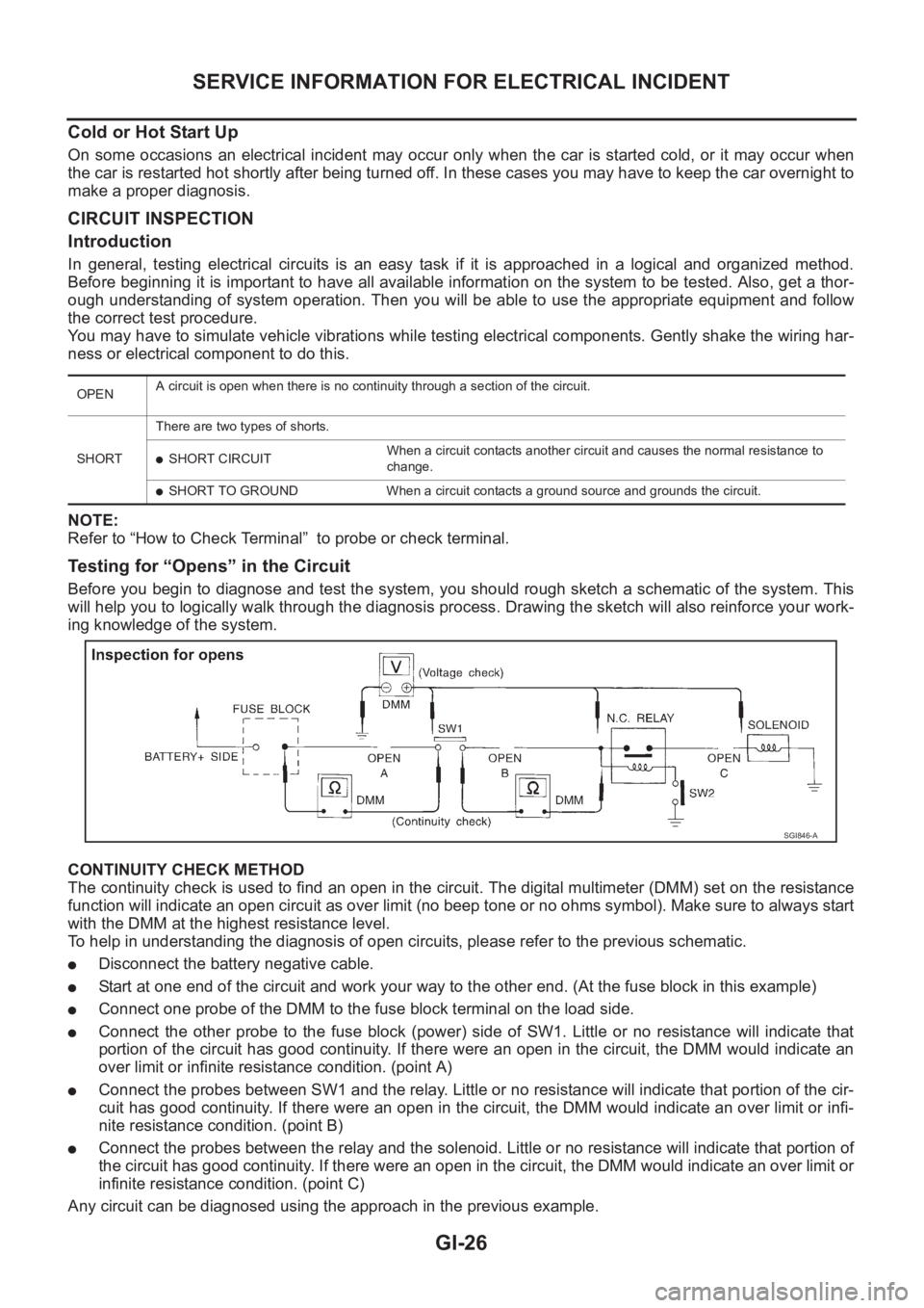
Before you begin to diagnose and test the system, you should rough sketch a schematic of the system. This
will help you to logically walk through the diagnosis process. Drawing the sketch will also reinforce your work-
ing knowledge of the system.
CONTINUITY CHECK METHOD
The continuity check is used to find an open in the circuit. The digital multimeter (DMM) set on the resistance
function will indicate an open circuit as over limit (no beep tone or no ohms symbol). Make sure to always start
with the DMM at the highest resistance level.
To help in understanding the diagnosis of open circuits, please refer to the previous schematic.
●Disconnect the battery negative cable.
●Start at one end of the circuit and work your way to the other end. (At the fuse block in this example)
●Connect one probe of the DMM to the fuse block terminal on the load side.
●Connect the other probe to the fuse block (power) side of SW1. Little or no resistance will indicate that
portion of the circuit has good continuity. If there were an open in the circuit, the DMM would indicate an
over limit or infinite resistance condition. (point A)
●Connect the probes between SW1 and the relay. Little or no resistance will indicate that portion of the cir-
cuit has good continuity. If there were an open in the circuit, the DMM would indicate an over limit or infi-
nite resistance condition. (point B)
●Connect the probes between the relay and the solenoid. Little or no resistance will indicate that portion of
the circuit has good continuity. If there were an open in the circuit, the DMM would indicate an over limit or
infinite resistance condition. (point C)
Any circuit can be diagnosed using the approach in the previous example.
OPENA circuit is open when there is no continuity through a section of the circuit.
SHORTThere are two types of shorts.
●SHORT CIRCUITWhen a circuit contacts another circuit and causes the normal resistance to
change.
●SHORT TO GROUND When a circuit contacts a ground source and grounds the circuit.
SGI846-A
Page 29 of 3833
SERVICE INFORMATION FOR ELECTRICAL INCIDENT
GI-27
C
D
E
F
G
H
I
J
K
L
MB
GI
VOLTAGE CHECK METHOD
To help in understanding the diagnosis of open circuits please refer to the previous schematic.
In any powered circuit, an open can be found by methodically checking the system for the presence of voltage.
This is done by switching the DMM to the voltage function.
●Connect one probe of the DMM to a known good ground.
●Begin probing at one end of the circuit and work your way to the other end.
●With SW1 open, probe at SW1 to check for voltage.
voltage; open is further down the circuit than SW1.
no voltage; open is between fuse block and SW1 (point A).
●Close SW1 and probe at relay.
voltage; open is further down the circuit than the relay.
no voltage; open is between SW1 and relay (point B).
●Close the relay and probe at the solenoid.
voltage; open is further down the circuit than the solenoid.
no voltage; open is between relay and solenoid (point C).
Any powered circuit can be diagnosed using the approach in the previous example.
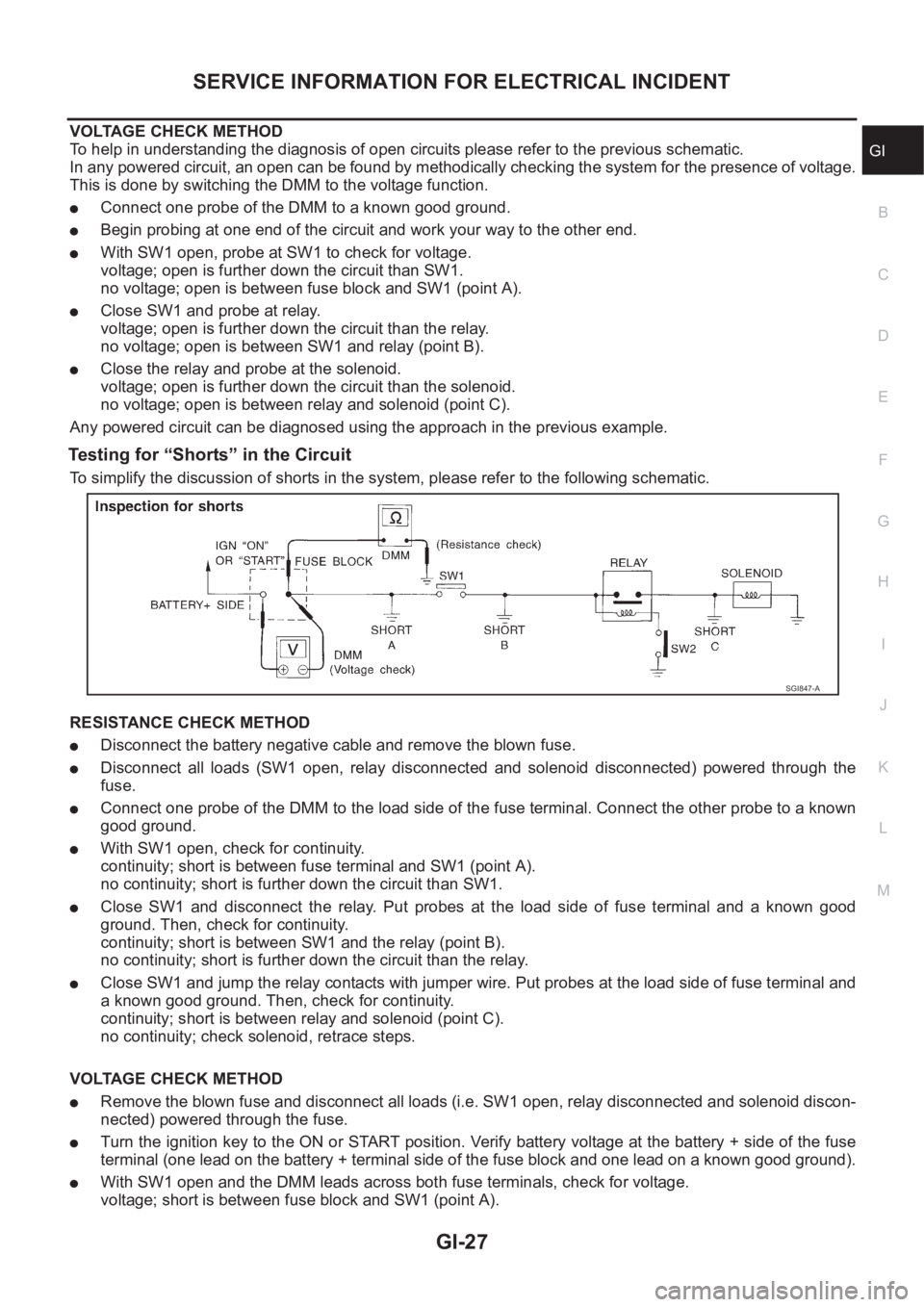
Testing for “Shorts” in the Circuit
To simplify the discussion of shorts in the system, please refer to the following schematic.
RESISTANCE CHECK METHOD
●Disconnect the battery negative cable and remove the blown fuse.
●Disconnect all loads (SW1 open, relay disconnected and solenoid disconnected) powered through the
fuse.
●Connect one probe of the DMM to the load side of the fuse terminal. Connect the other probe to a known
good ground.
●With SW1 open, check for continuity.
continuity; short is between fuse terminal and SW1 (point A).
no continuity; short is further down the circuit than SW1.
●Close SW1 and disconnect the relay. Put probes at the load side of fuse terminal and a known good
ground. Then, check for continuity.
continuity; short is between SW1 and the relay (point B).
no continuity; short is further down the circuit than the relay.
●Close SW1 and jump the relay contacts with jumper wire. Put probes at the load side of fuse terminal and
a known good ground. Then, check for continuity.
continuity; short is between relay and solenoid (point C).
no continuity; check solenoid, retrace steps.
VOLTAGE CHECK METHOD
●Remove the blown fuse and disconnect all loads (i.e. SW1 open, relay disconnected and solenoid discon-
nected) powered through the fuse.
●Turn the ignition key to the ON or START position. Verify battery voltage at the battery + side of the fuse
terminal (one lead on the battery + terminal side of the fuse block and one lead on a known good ground).
●With SW1 open and the DMM leads across both fuse terminals, check for voltage.
voltage; short is between fuse block and SW1 (point A).
SGI847-A
Page 31 of 3833
SERVICE INFORMATION FOR ELECTRICAL INCIDENT
GI-29
C
D
E
F
G
H
I
J
K
L
MB
GI
If repairs are needed always use wire that is of the same or larger gauge.
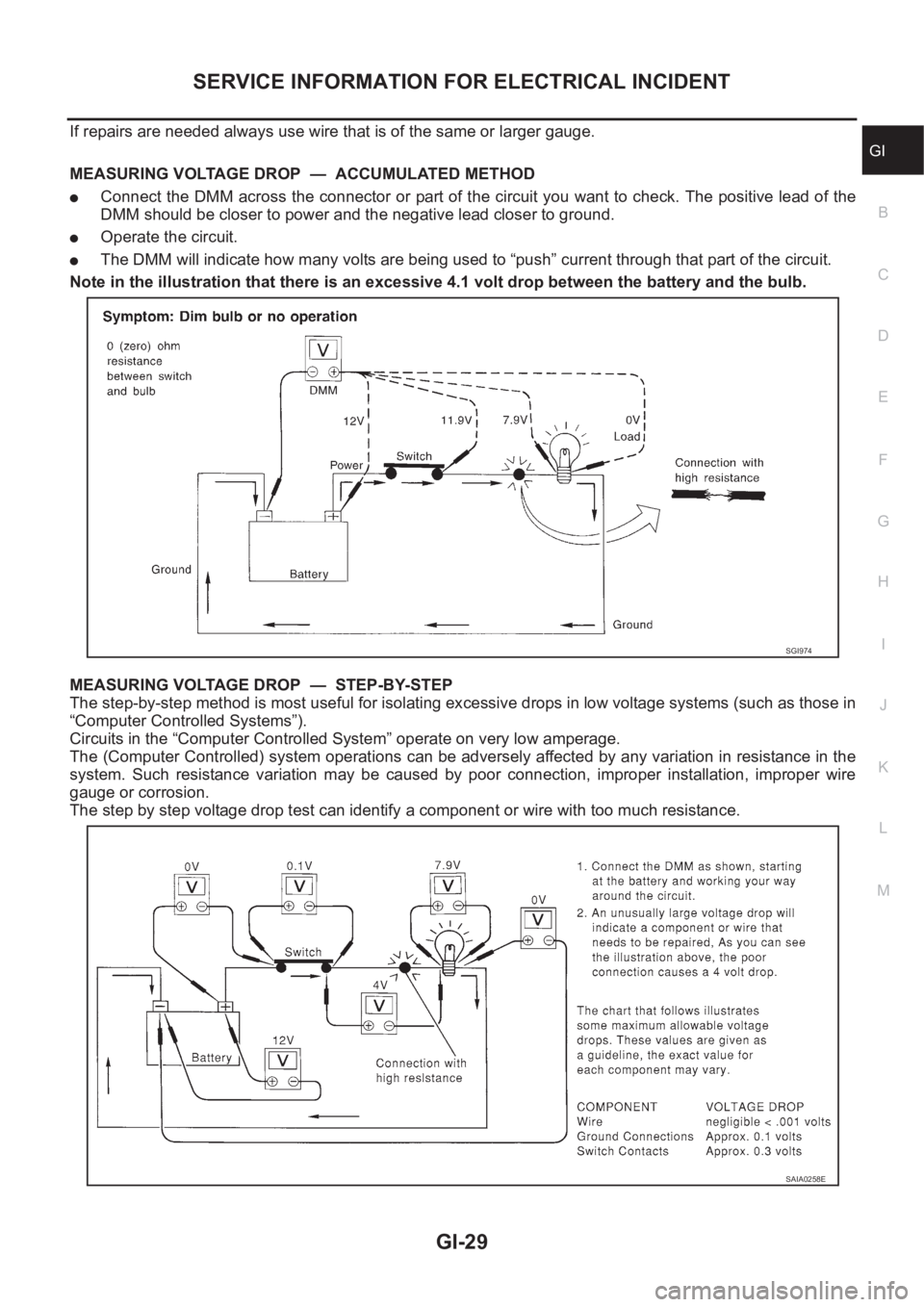
MEASURING VOLTAGE DROP — ACCUMULATED METHOD
●Connect the DMM across the connector or part of the circuit you want to check. The positive lead of the
DMM should be closer to power and the negative lead closer to ground.
●Operate the circuit.
●The DMM will indicate how many volts are being used to “push” current through that part of the circuit.
Note in the illustration that there is an excessive 4.1 volt drop between the battery and the bulb.
MEASURING VOLTAGE DROP — STEP-BY-STEP
The step-by-step method is most useful for isolating excessive drops in low voltage systems (such as those in
“Computer Controlled Systems”).
Circuits in the “Computer Controlled System” operate on very low amperage.
The (Computer Controlled) system operations can be adversely affected by any variation in resistance in the
system. Such resistance variation may be caused by poor connection, improper installation, improper wire
gauge or corrosion.
The step by step voltage drop test can identify a component or wire with too much resistance.
SGI974
SAIA0258E
Page 32 of 3833
GI-30
SERVICE INFORMATION FOR ELECTRICAL INCIDENT
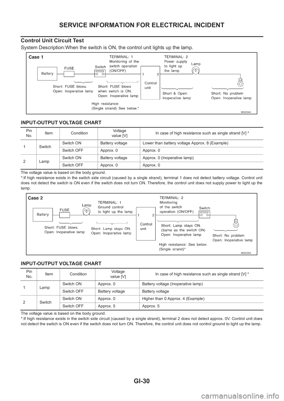
Control Unit Circuit Test
System Description:When the switch is ON, the control unit lights up the lamp.
INPUT-OUTPUT VOLTAGE CHART
The voltage value is based on the body ground.
*:If high resistance exists in the switch side circuit (caused by a single strand), terminal 1 does not detect battery voltage. Control unit
does not detect the switch is ON even if the switch does not turn ON. Therefore, the control unit does not supply power to light up the
lamp.
INPUT-OUTPUT VOLTAGE CHART
The voltage value is based on the body ground.
*:If high resistance exists in the switch side circuit (caused by a single strand), terminal 2 does not detect approx. 0V. Control unit does
not detect the switch is ON even if the switch does not turn ON. Therefore, the control unit does not control ground to light up the lamp.
MGI034A
Pin
No.Item ConditionVoltage
value [V]In case of high resistance such as single strand [V] *
1 SwitchSwitch ON Battery voltage Lower than battery voltage Approx. 8 (Example)
Switch OFF Approx. 0 Approx. 0
2LampSwitch ON Battery voltage Approx. 0 (Inoperative lamp)
Switch OFF Approx. 0 Approx. 0
MGI035A
Pin
No.Item ConditionVo l ta g e
value [V]In case of high resistance such as single strand [V] *
1LampSwitch ON Approx. 0 Battery voltage (Inoperative lamp)
Switch OFF Battery voltage Battery voltage
2 SwitchSwitch ON Approx. 0 Higher than 0 Approx. 4 (Example)
Switch OFF Approx. 5 Approx. 5