OBD port NISSAN X-TRAIL 2001 Service Owner's Manual
[x] Cancel search | Manufacturer: NISSAN, Model Year: 2001, Model line: X-TRAIL, Model: NISSAN X-TRAIL 2001Pages: 3833, PDF Size: 39.49 MB
Page 449 of 3833
TROUBLE DIAGNOSIS
EC-99
[QR25(WITH EURO-OBD)]
C
D
E
F
G
H
I
J
K
L
MA
EC
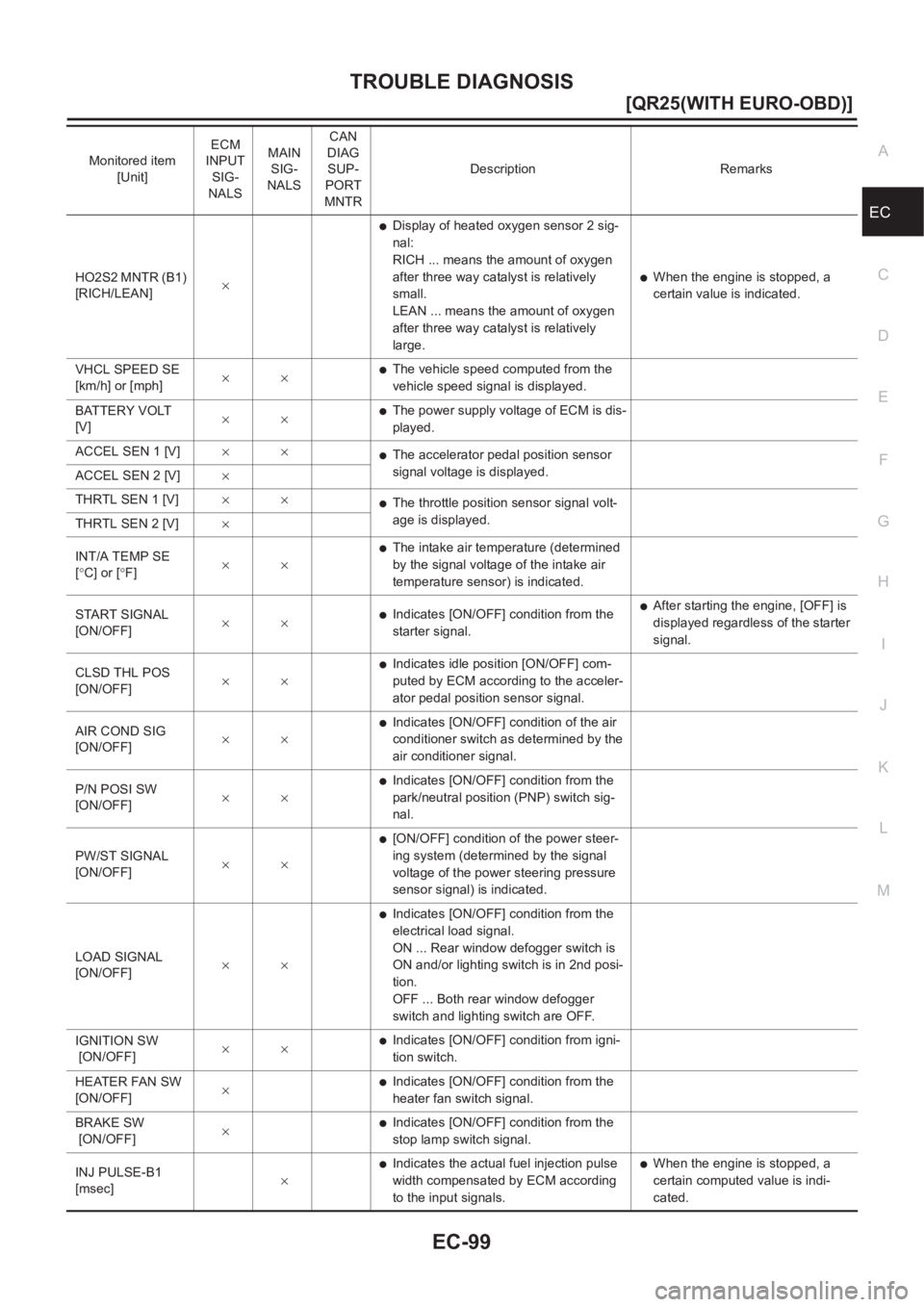
HO2S2 MNTR (B1)
[RICH/LEAN]×
●Display of heated oxygen sensor 2 sig-
nal:
RICH ... means the amount of oxygen
after three way catalyst is relatively
small.
LEAN ... means the amount of oxygen
after three way catalyst is relatively
large.
●When the engine is stopped, a
certain value is indicated.
VHCL SPEED SE
[km/h] or [mph]××
●The vehicle speed computed from the
vehicle speed signal is displayed.
BATTERY VOLT
[V]××
●The power supply voltage of ECM is dis-
played.
ACCEL SEN 1 [V]××
●The accelerator pedal position sensor
signal voltage is displayed.
ACCEL SEN 2 [V]×
THRTL SEN 1 [V]××
●The throttle position sensor signal volt-
age is displayed.
THRTL SEN 2 [V]×
INT/A TEMP SE
[°C] or [°F]××
●The intake air temperature (determined
by the signal voltage of the intake air
temperature sensor) is indicated.
START SIGNAL
[ON/OFF]××
●Indicates [ON/OFF] condition from the
starter signal.●After starting the engine, [OFF] is
displayed regardless of the starter
signal.
CLSD THL POS
[ON/OFF]××
●Indicates idle position [ON/OFF] com-
puted by ECM according to the acceler-
ator pedal position sensor signal.
AIR COND SIG
[ON/OFF]××
●Indicates [ON/OFF] condition of the air
conditioner switch as determined by the
air conditioner signal.
P/N POSI SW
[ON/OFF]××
●Indicates [ON/OFF] condition from the
park/neutral position (PNP) switch sig-
nal.
PW/ST SIGNAL
[ON/OFF]××
●[ON/OFF] condition of the power steer-
ing system (determined by the signal
voltage of the power steering pressure
sensor signal) is indicated.
LOAD SIGNAL
[ON/OFF]××
●Indicates [ON/OFF] condition from the
electrical load signal.
ON ... Rear window defogger switch is
ON and/or lighting switch is in 2nd posi-
tion.
OFF ... Both rear window defogger
switch and lighting switch are OFF.
IGNITION SW
[ON/OFF]××
●Indicates [ON/OFF] condition from igni-
tion switch.
HEATER FAN SW
[ON/OFF]×
●Indicates [ON/OFF] condition from the
heater fan switch signal.
BRAKE SW
[ON/OFF]×
●Indicates [ON/OFF] condition from the
stop lamp switch signal.
INJ PULSE-B1
[msec]×
●Indicates the actual fuel injection pulse
width compensated by ECM according
to the input signals.●When the engine is stopped, a
certain computed value is indi-
cated. Monitored item
[Unit]ECM
INPUT
SIG-
NALSMAIN
SIG-
NALSCAN
DIAG
SUP-
PORT
MNTRDescription Remarks
Page 450 of 3833
EC-100
[QR25(WITH EURO-OBD)]
TROUBLE DIAGNOSIS
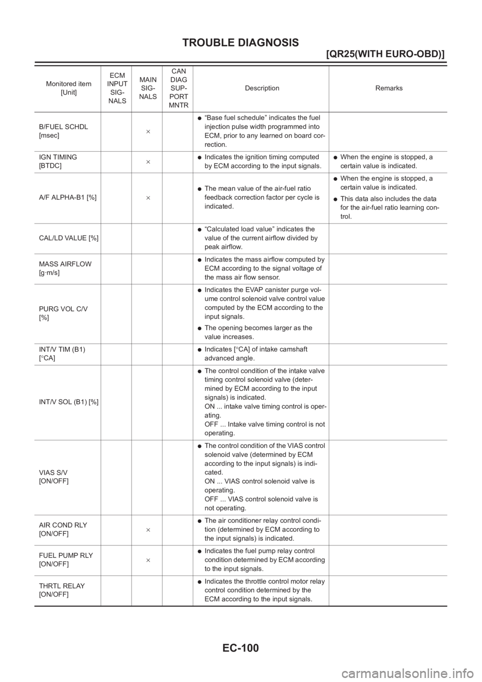
B/FUEL SCHDL
[msec]×
●“Base fuel schedule” indicates the fuel
injection pulse width programmed into
ECM, prior to any learned on board cor-
rection.
IGN TIMING
[BTDC]×
●Indicates the ignition timing computed
by ECM according to the input signals.●When the engine is stopped, a
certain value is indicated.
A/F ALPHA-B1 [%]×
●The mean value of the air-fuel ratio
feedback correction factor per cycle is
indicated.
●When the engine is stopped, a
certain value is indicated.
●This data also includes the data
for the air-fuel ratio learning con-
trol.
CAL/LD VALUE [%]
●“Calculated load value” indicates the
value of the current airflow divided by
peak airflow.
MASS AIRFLOW
[g·m/s]
●Indicates the mass airflow computed by
ECM according to the signal voltage of
the mass air flow sensor.
PURG VOL C/V
[%]
●Indicates the EVAP canister purge vol-
ume control solenoid valve control value
computed by the ECM according to the
input signals.
●The opening becomes larger as the
value increases.
INT/V TIM (B1)
[°CA]
●Indicates [°CA] of intake camshaft
advanced angle.
INT/V SOL (B1) [%]
●The control condition of the intake valve
timing control solenoid valve (deter-
mined by ECM according to the input
signals) is indicated.
ON ... intake valve timing control is oper-
ating.
OFF ... Intake valve timing control is not
operating.
VIAS S/V
[ON/OFF]
●The control condition of the VIAS control
solenoid valve (determined by ECM
according to the input signals) is indi-
cated.
ON ... VIAS control solenoid valve is
operating.
OFF ... VIAS control solenoid valve is
not operating.
AIR COND RLY
[ON/OFF]×
●The air conditioner relay control condi-
tion (determined by ECM according to
the input signals) is indicated.
FUEL PUMP RLY
[ON/OFF]×
●Indicates the fuel pump relay control
condition determined by ECM according
to the input signals.
THRTL RELAY
[ON/OFF]
●Indicates the throttle control motor relay
control condition determined by the
ECM according to the input signals. Monitored item
[Unit]ECM
INPUT
SIG-
NALSMAIN
SIG-
NALSCAN
DIAG
SUP-
PORT
MNTRDescription Remarks
Page 451 of 3833
TROUBLE DIAGNOSIS
EC-101
[QR25(WITH EURO-OBD)]
C
D
E
F
G
H
I
J
K
L
MA
EC
NOTE:
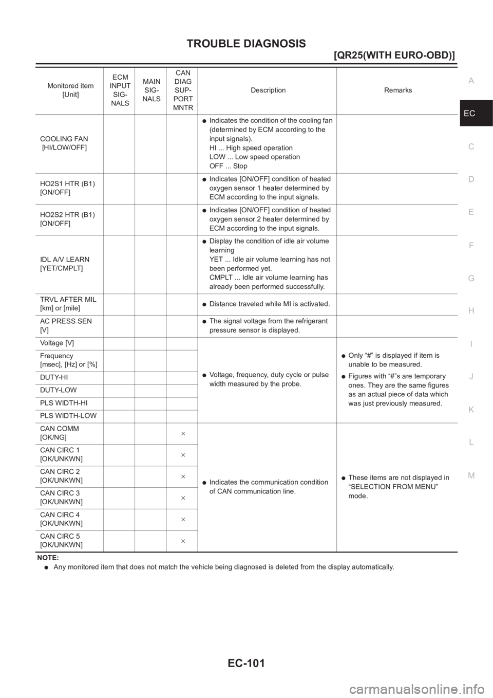
●Any monitored item that does not match the vehicle being diagnosed is deleted from the display automatically. COOLING FAN
[HI/LOW/OFF]
●Indicates the condition of the cooling fan
(determined by ECM according to the
input signals).
HI ... High speed operation
LOW ... Low speed operation
OFF ... Stop
HO2S1 HTR (B1)
[ON/OFF]
●Indicates [ON/OFF] condition of heated
oxygen sensor 1 heater determined by
ECM according to the input signals.
HO2S2 HTR (B1)
[ON/OFF]
●Indicates [ON/OFF] condition of heated
oxygen sensor 2 heater determined by
ECM according to the input signals.
IDL A/V LEARN
[YET/CMPLT]
●Display the condition of idle air volume
learning
YET ... Idle air volume learning has not
been performed yet.
CMPLT ... Idle air volume learning has
already been performed successfully.
TRVL AFTER MIL
[km] or [mile]
●Distance traveled while MI is activated.
AC PRESS SEN
[V]
●The signal voltage from the refrigerant
pressure sensor is displayed.
Voltage [V]
●Voltage, frequency, duty cycle or pulse
width measured by the probe.
●Only “#” is displayed if item is
unable to be measured.
●Figures with “#”s are temporary
ones. They are the same figures
as an actual piece of data which
was just previously measured. Frequency
[msec], [Hz] or [%]
DUTY-HI
DUTY-LOW
PLS WIDTH-HI
PLS WIDTH-LOW
CAN COMM
[OK/NG]×
●Indicates the communication condition
of CAN communication line.●These items are not displayed in
“SELECTION FROM MENU”
mode. CAN CIRC 1
[OK/UNKWN]×
CAN CIRC 2
[OK/UNKWN]×
CAN CIRC 3
[OK/UNKWN]×
CAN CIRC 4
[OK/UNKWN]×
CAN CIRC 5
[OK/UNKWN]× Monitored item
[Unit]ECM
INPUT
SIG-
NALSMAIN
SIG-
NALSCAN
DIAG
SUP-
PORT
MNTRDescription Remarks
Page 453 of 3833
TROUBLE DIAGNOSIS
EC-103
[QR25(WITH EURO-OBD)]
C
D
E
F
G
H
I
J
K
L
MA
EC
DTC & SRT CONFIRMATION MODE
SRT STATUS Mode
For details, refer to EC-48, "SYSTEM READINESS TEST (SRT) CODE" .
SRT Work Support Mode
This mode enables a technician to drive a vehicle to set the SRT while monitoring the SRT status.
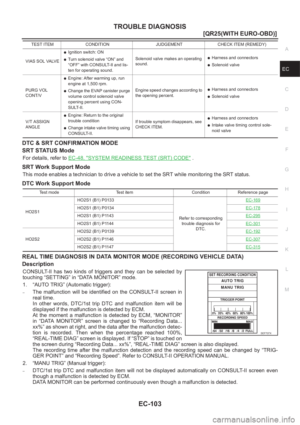
DTC Work Support Mode
REAL TIME DIAGNOSIS IN DATA MONITOR MODE (RECORDING VEHICLE DATA)
Description
CONSULT-II has two kinds of triggers and they can be selected by
touching “SETTING” in “DATA MONITOR” mode.
1. “AUTO TRIG” (Automatic trigger):
–The malfunction will be identified on the CONSULT-II screen in
real time.
In other words, DTC/1st trip DTC and malfunction item will be
displayed if the malfunction is detected by ECM.
At the moment a malfunction is detected by ECM, “MONITOR”
in “DATA MONITOR” screen is changed to “Recording Data...
xx%” as shown at right, and the data after the malfunction detec-
tion is recorded. Then when the percentage reached 100%,
“REAL-TIME DIAG” screen is displayed. If “STOP” is touched on
the screen during “Recording Data... xx%”, “REAL-TIME DIAG” screen is also displayed.
The recording time after the malfunction detection and the recording speed can be changed by “TRIG-
GER POINT” and “Recording Speed”. Refer to CONSULT-II OPERATION MANUAL.
2. “MANU TRIG” (Manual trigger):
–DTC/1st trip DTC and malfunction item will not be displayed automatically on CONSULT-II screen even
though a malfunction is detected by ECM.
DATA MONITOR can be performed continuously even though a malfunction is detected.
VIAS SOL VALVE
●Ignition switch: ON
●Turn solenoid valve “ON” and
“OFF” with CONSULT-II and lis-
ten for operating sound.Solenoid valve makes an operating
sound.●Harness and connectors
●Solenoid valve
PURG VOL
CONT/V
●Engine: After warming up, run
engine at 1,500 rpm.
●Change the EVAP canister purge
volume control solenoid valve
opening percent using CON-
SULT-II.Engine speed changes according to
the opening percent.●Harness and connectors
●Solenoid valve
V/T ASSIGN
ANGLE
●Engine: Return to the original
trouble condition
●Change intake valve timing using
CONSULT-II.If trouble symptom disappears, see
CHECK ITEM.
●Harness and connectors
●Intake valve timing control sole-
noid valve TEST ITEM CONDITION JUDGEMENT CHECK ITEM (REMEDY)
Test mode Test item Condition Reference page
HO2S1HO2S1 (B1) P0133
Refer to corresponding
trouble diagnosis for
DTC.EC-169
HO2S1 (B1) P0134EC-178
HO2S1 (B1) P1143EC-295
HO2S1 (B1) P1144EC-301
HO2S2HO2S2 (B1) P0139EC-192HO2S2 (B1) P1146EC-307
HO2S2 (B1) P1147EC-315
SEF706XSEF707X
Page 465 of 3833
TROUBLE DIAGNOSIS FOR INTERMITTENT INCIDENT
EC-115
[QR25(WITH EURO-OBD)]
C
D
E
F
G
H
I
J
K
L
MA
EC
TROUBLE DIAGNOSIS FOR INTERMITTENT INCIDENTPFP:00006
DescriptionEBS00M19
Intermittent incidents (I/I) may occur. In many cases, the incident resolves itself (the part or circuit function
returns to normal without intervention). It is important to realize that the symptoms described in the customer's
complaint often do not recur on (1st trip) DTC visits. Realize also that the most frequent cause of I/I occur-
rences is poor electrical connections. Because of this, the conditions under which the incident occurred may
not be clear. Therefore, circuit checks made as part of the standard diagnostic procedure may not indicate the
specific malfunctioning area.
Common I/I Report Situations
Diagnostic ProcedureEBS00M1A
1.INSPECTION START
Erase (1st trip) DTCs. Refer to EC-1142, "
HOW TO ERASE EMISSION-RELATED DIAGNOSTIC INFORMA-
TION" .
>> GO TO 2.
2.CHECK GROUND TERMINALS
Check ground terminals for corroding or loose connection.
Refer to GI-23, "
How to Perform Efficient Diagnosis for an Electrical Incident" , “CIRCUIT INSPECTION”,
“Ground Inspection”.
OK or NG
OK >> GO TO 3.
NG >> Repair or replace.
3.SEARCH FOR ELECTRICAL INCIDENT
Perform GI-23, "
How to Perform Efficient Diagnosis for an Electrical Incident" , “INCIDENT SIMULATION
TESTS”.
OK or NG
OK >>INSPECTION END
NG >> Repair or replace.
STEP in Work Flow Situation
II The CONSULT-II is used. The SELF-DIAG RESULTS screen shows time data other than “0” or “[1t]”.
III The symptom described by the customer does not recur.
IV (1st trip) DTC does not appear during the DTC Confirmation Procedure.
VI The Diagnostic Procedure for PXXXX does not indicate the malfunctioning area.
Page 474 of 3833
EC-124
[QR25(WITH EURO-OBD)]
DTC U1000 CAN COMMUNICATION LINE
Diagnostic Procedure
EBS00M1J
1. INSPECTION START
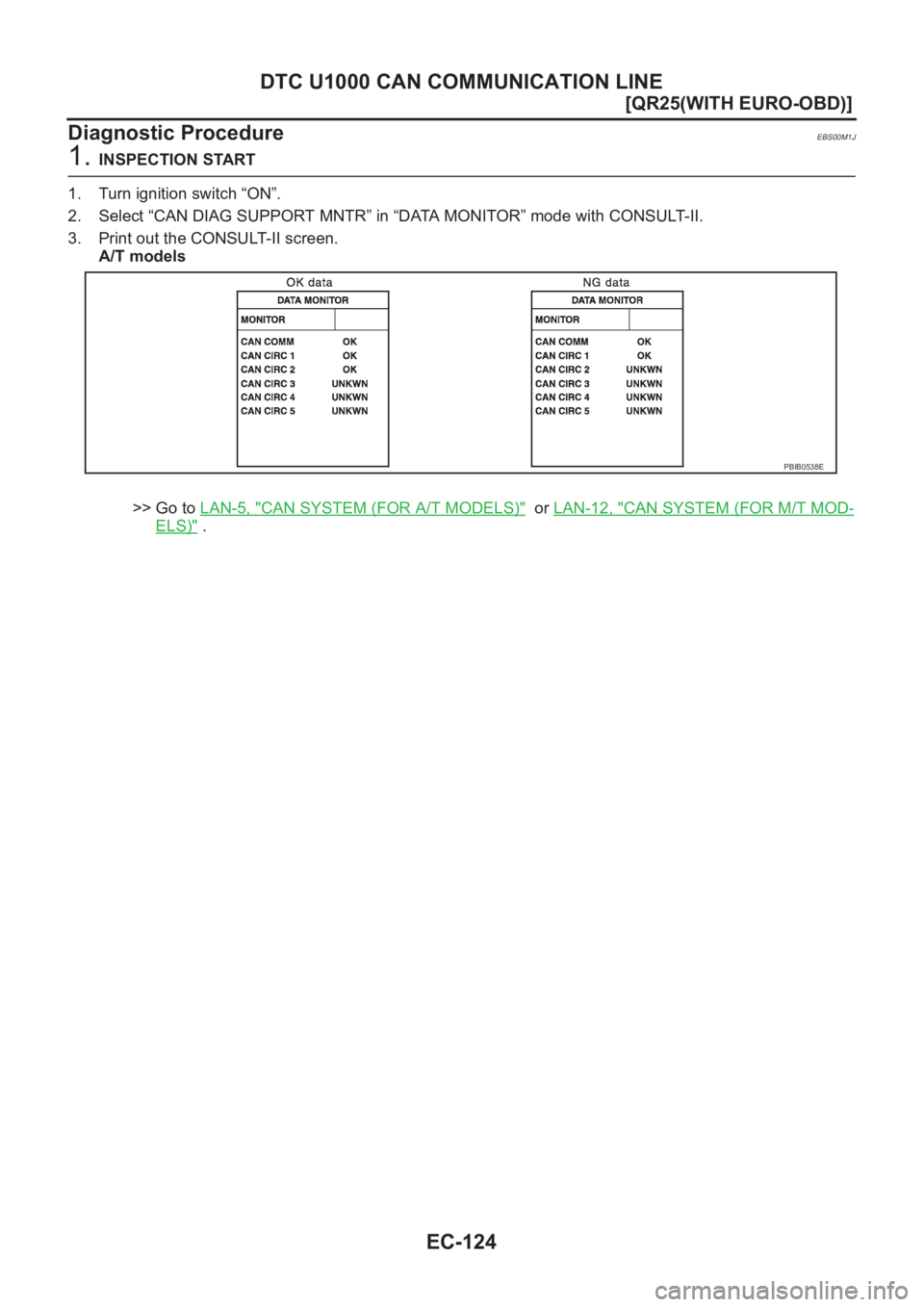
1. Turn ignition switch “ON”.
2. Select “CAN DIAG SUPPORT MNTR” in “DATA MONITOR” mode with CONSULT-II.
3. Print out the CONSULT-II screen.
A/T models
>> Go to LAN-5, "
CAN SYSTEM (FOR A/T MODELS)" or LAN-12, "CAN SYSTEM (FOR M/T MOD-
ELS)" .
PBIB0538E
Page 476 of 3833
EC-126
[QR25(WITH EURO-OBD)]
DTC P0011 IVT CONTROL
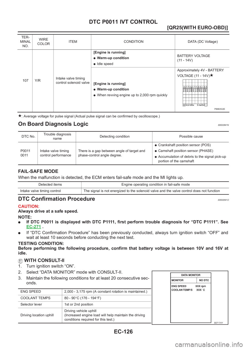
: Average voltage for pulse signal (Actual pulse signal can be confirmed by oscilloscope.)
On Board Diagnosis LogicEBS00M1N
FAIL-SAFE MODE
When the malfunction is detected, the ECM enters fail-safe mode and the MI lights up.
DTC Confirmation ProcedureEBS00M1O
CAUTION:
Always drive at a safe speed.
NOTE:
●If DTC P0011 is displayed with DTC P1111, first perform trouble diagnosis for “DTC P1111”. See
EC-271
.
●If “DTC Confirmation Procedure” has been previously conducted, always turn ignition switch “OFF” and
wait at least 10 seconds before conducting the next test.
TESTING CONDITION:
Before performing the following procedure, confirm that battery voltage is between 10V and 16V at
idle.
WITH CONSULT-II
1. Turn ignition switch “ON”.
2. Select “DATA MONITOR” mode with CONSULT-II.
3. Maintain the following conditions for at least 20 consecutive sec-
onds.
TER-
MINAL
NO.WIRE
COLORITEM CONDITION DATA (DC Voltage)
107 Y/RIntake valve timing
control solenoid valve[Engine is running]
●Warm-up condition
●Idle speedBATTERY VOLTAGE
(11 - 14V)
[Engine is running]
●Warm-up condition
●When revving engine up to 2,000 rpm quicklyApproximately 4V - BATTERY
VOLTAGE (11 - 14V)
PBIB0532E
DTC No.Trouble diagnosis
nameDetecting condition Possible cause
P0011
0011Intake valve timing
control performanceThere is a gap between angle of target and
phase-control angle degree.
●Crankshaft position sensor (POS)
●Camshaft position sensor (PHASE)
●Accumulation of debris to the signal pick-up
portion of the camshaft
Detected items Engine operating condition in fail-safe mode
Intake valve timing control The signal is not energized to the solenoid valve and the valve control does not function
ENG SPEED 2,000 - 3,175 rpm (A constant rotation is maintained.)
COOLANT TEMPS 80 - 90°C (176 - 194°F)
Selector lever 1st or 2nd position
Driving location uphillDriving vehicle uphill
(Increased engine load will help maintain the driving
conditions required for this test.)
SEF174Y
Page 520 of 3833
EC-170
[QR25(WITH EURO-OBD)]
DTC P0133 HO2S1
On Board Diagnosis Logic
EBS00M3L
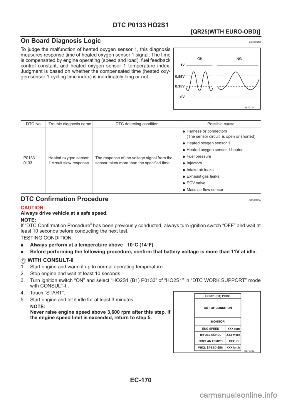
To judge the malfunction of heated oxygen sensor 1, this diagnosis
measures response time of heated oxygen sensor 1 signal. The time
is compensated by engine operating (speed and load), fuel feedback
control constant, and heated oxygen sensor 1 temperature index.
Judgment is based on whether the compensated time (heated oxy-
gen sensor 1 cycling time index) is inordinately long or not.
DTC Confirmation ProcedureEBS00M3M
CAUTION:
Always drive vehicle at a safe speed.
NOTE:
If “DTC Confirmation Procedure” has been previously conducted, always turn ignition switch “OFF” and wait at
least 10 seconds before conducting the next test.
TESTING CONDITION:
●Always perform at a temperature above −10°C (14°F).
●Before performing the following procedure, confirm that battery voltage is more than 11V at idle.
WITH CONSULT-II
1. Start engine and warm it up to normal operating temperature.
2. Stop engine and wait at least 10 seconds.
3. Turn ignition switch “ON” and select “HO2S1 (B1) P0133” of “HO2S1” in “DTC WORK SUPPORT” mode
with CONSULT-II.
4. Touch “START”.
5. Start engine and let it idle for at least 3 minutes.
NOTE:
Never raise engine speed above 3,600 rpm after this step. If
the engine speed limit is exceeded, return to step 5.
SEF010V
DTC No. Trouble diagnosis name DTC detecting condition Possible cause
P0133
0133Heated oxygen sensor
1 circuit slow responseThe response of the voltage signal from the
sensor takes more than the specified time.
●Harness or connectors
(The sensor circuit is open or shorted)
●Heated oxygen sensor 1
●Heated oxygen sensor 1 heater
●Fuel pressure
●Injectors
●Intake air leaks
●Exhaust gas leaks
●PCV valve
●Mass air flow sensor
SEF338Z
Page 524 of 3833
EC-174
[QR25(WITH EURO-OBD)]
DTC P0133 HO2S1
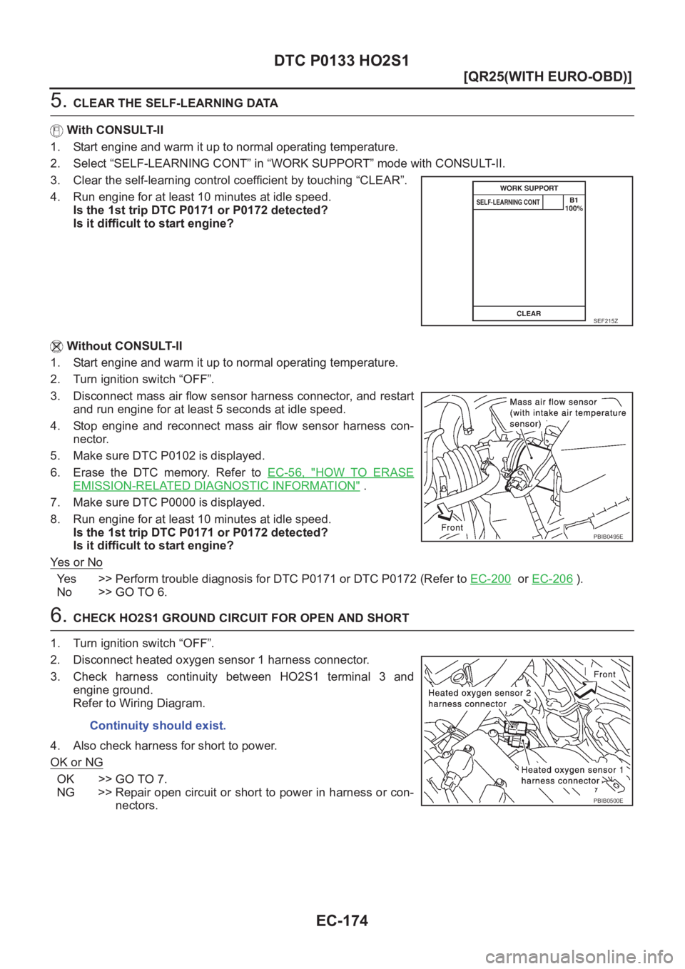
5. CLEAR THE SELF-LEARNING DATA
With CONSULT-II
1. Start engine and warm it up to normal operating temperature.
2. Select “SELF-LEARNING CONT” in “WORK SUPPORT” mode with CONSULT-II.
3. Clear the self-learning control coefficient by touching “CLEAR”.
4. Run engine for at least 10 minutes at idle speed.
Is the 1st trip DTC P0171 or P0172 detected?
Is it difficult to start engine?
Without CONSULT-II
1. Start engine and warm it up to normal operating temperature.
2. Turn ignition switch “OFF”.
3. Disconnect mass air flow sensor harness connector, and restart
and run engine for at least 5 seconds at idle speed.
4. Stop engine and reconnect mass air flow sensor harness con-
nector.
5. Make sure DTC P0102 is displayed.
6. Erase the DTC memory. Refer to EC-56, "
HOW TO ERASE
EMISSION-RELATED DIAGNOSTIC INFORMATION" .
7. Make sure DTC P0000 is displayed.
8. Run engine for at least 10 minutes at idle speed.
Is the 1st trip DTC P0171 or P0172 detected?
Is it difficult to start engine?
Ye s o r N o
Yes >> Perform trouble diagnosis for DTC P0171 or DTC P0172 (Refer to EC-200 or EC-206 ).
No >> GO TO 6.
6. CHECK HO2S1 GROUND CIRCUIT FOR OPEN AND SHORT
1. Turn ignition switch “OFF”.
2. Disconnect heated oxygen sensor 1 harness connector.
3. Check harness continuity between HO2S1 terminal 3 and
engine ground.
Refer to Wiring Diagram.
4. Also check harness for short to power.
OK or NG
OK >> GO TO 7.
NG >> Repair open circuit or short to power in harness or con-
nectors.
SEF215Z
PBIB0495E
Continuity should exist.
PBIB0500E
Page 529 of 3833
DTC P0134 HO2S1
EC-179
[QR25(WITH EURO-OBD)]
C
D
E
F
G
H
I
J
K
L
MA
EC
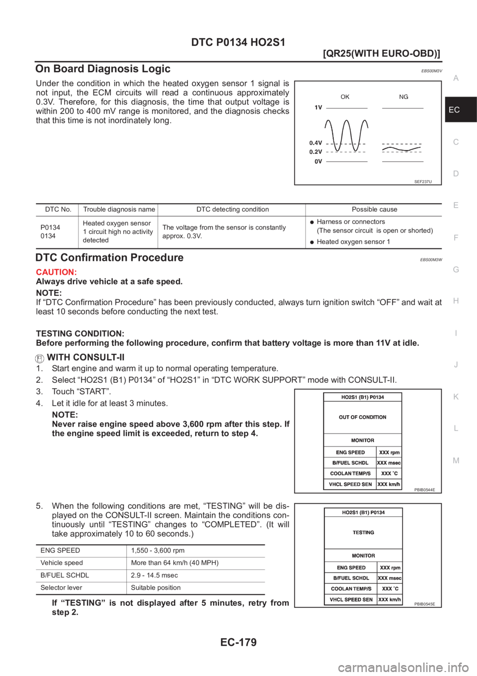
On Board Diagnosis LogicEBS00M3V
Under the condition in which the heated oxygen sensor 1 signal is
not input, the ECM circuits will read a continuous approximately
0.3V. Therefore, for this diagnosis, the time that output voltage is
within 200 to 400 mV range is monitored, and the diagnosis checks
that this time is not inordinately long.
DTC Confirmation ProcedureEBS00M3W
CAUTION:
Always drive vehicle at a safe speed.
NOTE:
If “DTC Confirmation Procedure” has been previously conducted, always turn ignition switch “OFF” and wait at
least 10 seconds before conducting the next test.
TESTING CONDITION:
Before performing the following procedure, confirm that battery voltage is more than 11V at idle.
WITH CONSULT-II
1. Start engine and warm it up to normal operating temperature.
2. Select “HO2S1 (B1) P0134” of “HO2S1” in “DTC WORK SUPPORT” mode with CONSULT-II.
3. Touch “START”.
4. Let it idle for at least 3 minutes.
NOTE:
Never raise engine speed above 3,600 rpm after this step. If
the engine speed limit is exceeded, return to step 4.
5. When the following conditions are met, “TESTING” will be dis-
played on the CONSULT-II screen. Maintain the conditions con-
tinuously until “TESTING” changes to “COMPLETED”. (It will
take approximately 10 to 60 seconds.)
If “TESTING” is not displayed after 5 minutes, retry from
step 2.
SEF237U
DTC No. Trouble diagnosis name DTC detecting condition Possible cause
P0134
0134Heated oxygen sensor
1 circuit high no activity
detectedThe voltage from the sensor is constantly
approx. 0.3V.
●Harness or connectors
(The sensor circuit is open or shorted)
●Heated oxygen sensor 1
PBIB0544E
ENG SPEED 1,550 - 3,600 rpm
Vehicle speed More than 64 km/h (40 MPH)
B/FUEL SCHDL 2.9 - 14.5 msec
Selector lever Suitable position
PBIB0545E