Shaft NISSAN X-TRAIL 2001 Service Owner's Manual
[x] Cancel search | Manufacturer: NISSAN, Model Year: 2001, Model line: X-TRAIL, Model: NISSAN X-TRAIL 2001Pages: 3833, PDF Size: 39.49 MB
Page 93 of 3833
TIMING CHAIN
EM-43
[QR]
C
D
E
F
G
H
I
J
K
L
MA
EM
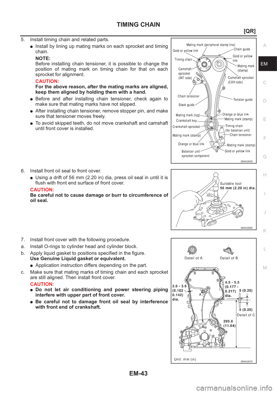
5. Install timing chain and related parts.
●Install by lining up mating marks on each sprocket and timing
chain.
NOTE:
Before installing chain tensioner, it is possible to change the
position of mating mark on timing chain for that on each
sprocket for alignment.
CAUTION:
For the above reason, after the mating marks are aligned,
keep them aligned by holding them with a hand.
●Before and after installing chain tensioner, check again to
make sure that mating marks have not slipped.
●After installing chain tensioner, remove stopper pin, and make
sure that tensioner moves freely.
●To avoid skipped teeth, do not move crankshaft and camshaft
until front cover is installed.
6. Install front oil seal to front cover.
●Using a drift of 56 mm (2.20 in) dia, press oil seal in until it is
flush with front end surface of front cover.
CAUTION:
Be careful not to cause damage or burr to circumference of
oil seal.
7. Install front cover with the following procedure.
a. Install O-rings to cylinder head and cylinder block.
b. Apply liquid gasket to positions specified in the figure.
Use Genuine Liquid gasket or equivalent.
●Application instruction differs depending on the part.
c. Make sure that mating marks of timing chain and each sprocket
are still aligned. Then install front cover.
CAUTION:
●Do not let air conditioning and power steering piping
interfere with upper part of front cover.
●Be careful not to damage front oil seal by interference
with front end of crankshaft.
SBIA0265E
SBIA0266E
SBIA0267E
Page 94 of 3833

EM-44
[QR]
TIMING CHAIN
d. Tighten mounting bolts in the numerical order shown in the fig-
ure.
e. After all bolts are tightened, retighten them to specified torque.
CAUTION:
Be sure to wipe off any excessive liquid gasket leaking to
surface for fitting oil pan.
8. Install chain guide between camshaft sprockets.
9. Install intake valve timing control cover with the following procedure.
a. Install intake valve timing control solenoid valves to intake valve timing control cover.
b. Install oil rings to the intake camshaft sprocket insertion points on intake valve timing control backside
cover.
c. Install O-ring to front cover.
d. Apply liquid gasket to the positions in the figure.
Use Genuine Liquid gasket or equivalent.
e. Tighten mounting bolts in the numerical order shown in the fig-
ure.
10. Insert crankshaft pulley by aligning with crankshaft key.
●Tap its center with a plastic hammer to insert.
●Do not tap belt hook.
11. Tighten crankshaft pulley mounting bolt.
KBIA0083E
SBIA0260E
KBIA0085E
Page 95 of 3833
TIMING CHAIN
EM-45
[QR]
C
D
E
F
G
H
I
J
K
L
MA
EM
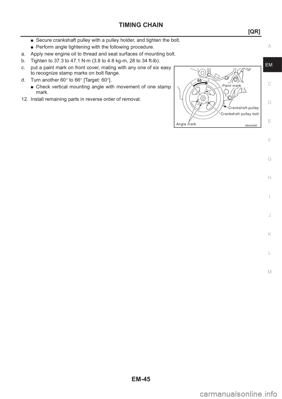
●Secure crankshaft pulley with a pulley holder, and tighten the bolt.
●Perform angle tightening with the following procedure.
a. Apply new engine oil to thread and seat surfaces of mounting bolt.
b. Tighten to 37.3 to 47.1 N·m (3.8 to 4.8 kg-m, 28 to 34 ft-lb).
c. put a paint mark on front cover, mating with any one of six easy
to recognize stamp marks on bolt flange.
d. Turn another 60° to 66° [Target: 60°].
●Check vertical mounting angle with movement of one stamp
mark.
12. Install remaining parts in reverse order of removal.
SBIA0268E
Page 96 of 3833
EM-46
[QR]
CAMSHAFT
CAMSHAFT
PFP:13001
Removal and InstallationEBS00LS2
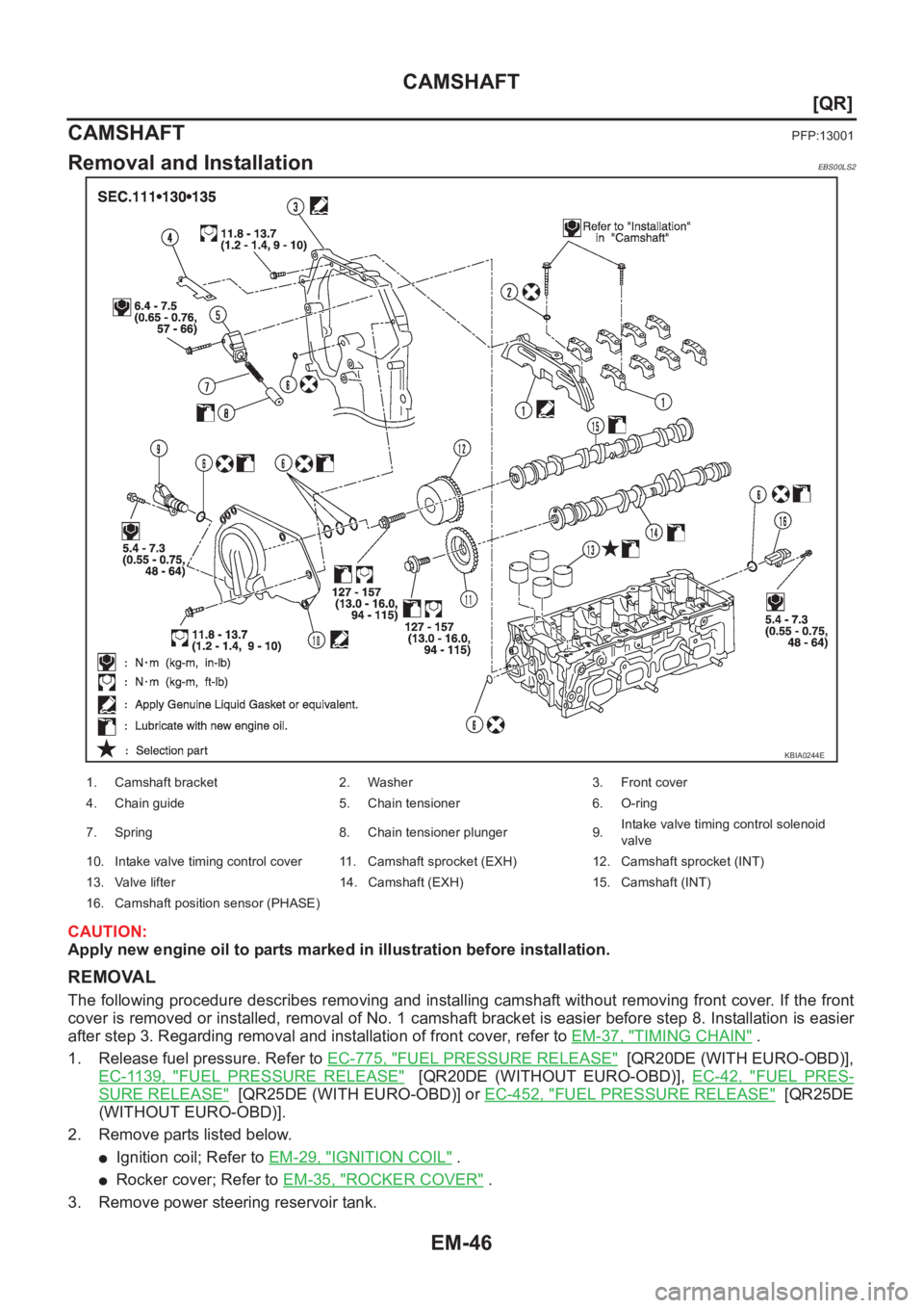
CAUTION:
Apply new engine oil to parts marked in illustration before installation.
REMOVAL
The following procedure describes removing and installing camshaft without removing front cover. If the front
cover is removed or installed, removal of No. 1 camshaft bracket is easier before step 8. Installation is easier
after step 3. Regarding removal and installation of front cover, refer to EM-37, "
TIMING CHAIN" .
1. Release fuel pressure. Refer to EC-775, "
FUEL PRESSURE RELEASE" [QR20DE (WITH EURO-OBD)],
EC-1139, "
FUEL PRESSURE RELEASE" [QR20DE (WITHOUT EURO-OBD)], EC-42, "FUEL PRES-
SURE RELEASE" [QR25DE (WITH EURO-OBD)] or EC-452, "FUEL PRESSURE RELEASE" [QR25DE
(WITHOUT EURO-OBD)].
2. Remove parts listed below.
●Ignition coil; Refer to EM-29, "IGNITION COIL" .
●Rocker cover; Refer to EM-35, "ROCKER COVER" .
3. Remove power steering reservoir tank.
KBIA0244E
1. Camshaft bracket 2. Washer 3. Front cover
4. Chain guide 5. Chain tensioner 6. O-ring
7. Spring 8. Chain tensioner plunger 9.Intake valve timing control solenoid
valve
10. Intake valve timing control cover 11. Camshaft sprocket (EXH) 12. Camshaft sprocket (INT)
13. Valve lifter 14. Camshaft (EXH) 15. Camshaft (INT)
16. Camshaft position sensor (PHASE)
Page 97 of 3833
CAMSHAFT
EM-47
[QR]
C
D
E
F
G
H
I
J
K
L
MA
EM
4. Remove Intake valve timing control cover.
a. Loosen bolts in reverse order shown in the figure.
b. Disconnect intake valve timing control solenoid valve harness
connector, and remove intake valve timing control solenoid
valve.
c. Remove the cover using Tool (Seal cutter).
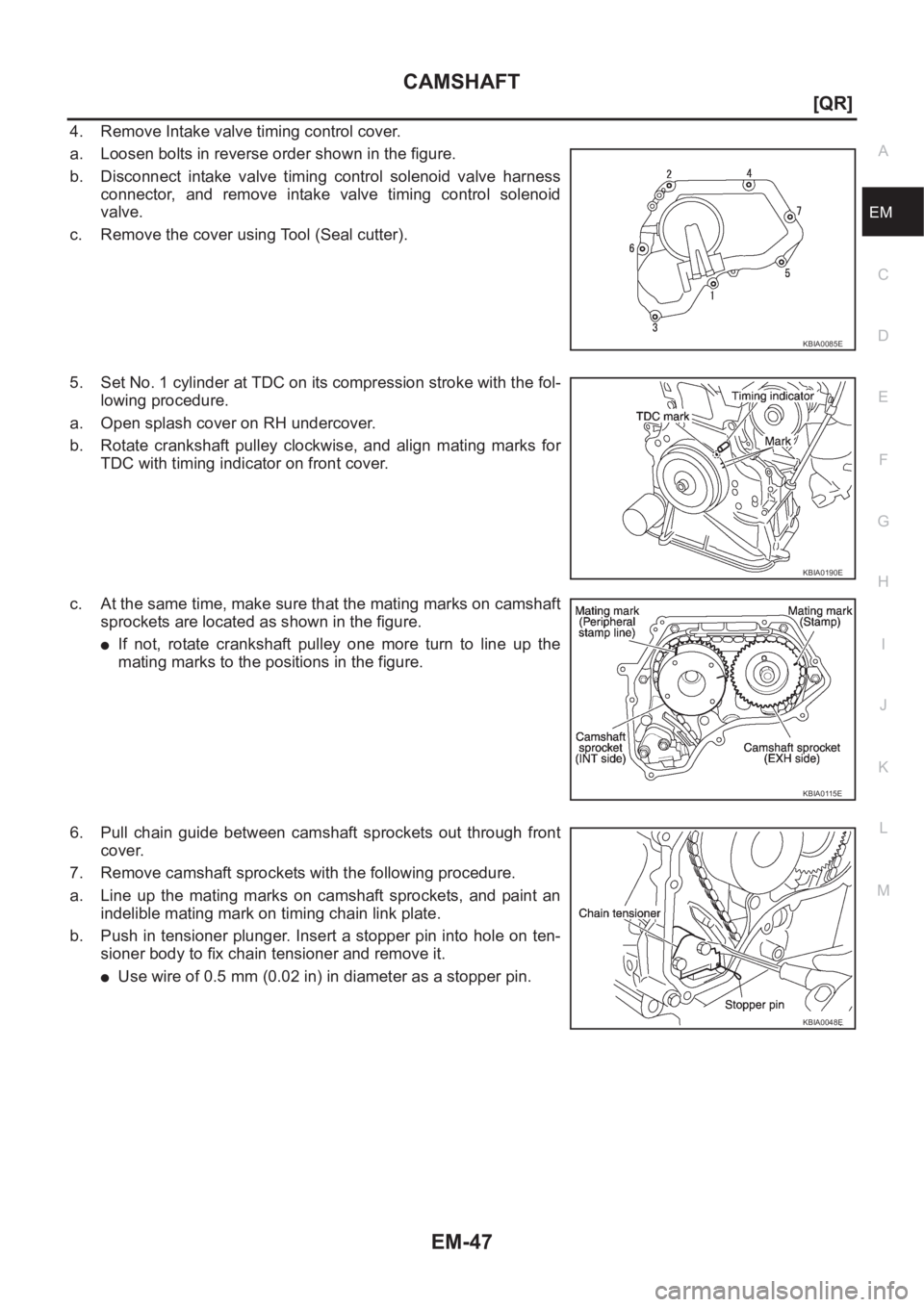
5. Set No. 1 cylinder at TDC on its compression stroke with the fol-
lowing procedure.
a. Open splash cover on RH undercover.
b. Rotate crankshaft pulley clockwise, and align mating marks for
TDC with timing indicator on front cover.
c. At the same time, make sure that the mating marks on camshaft
sprockets are located as shown in the figure.
●If not, rotate crankshaft pulley one more turn to line up the
mating marks to the positions in the figure.
6. Pull chain guide between camshaft sprockets out through front
cover.
7. Remove camshaft sprockets with the following procedure.
a. Line up the mating marks on camshaft sprockets, and paint an
indelible mating mark on timing chain link plate.
b. Push in tensioner plunger. Insert a stopper pin into hole on ten-
sioner body to fix chain tensioner and remove it.
●Use wire of 0.5 mm (0.02 in) in diameter as a stopper pin.
KBIA0085E
KBIA0190E
KBIA0115E
KBIA0048E
Page 98 of 3833
EM-48
[QR]
CAMSHAFT
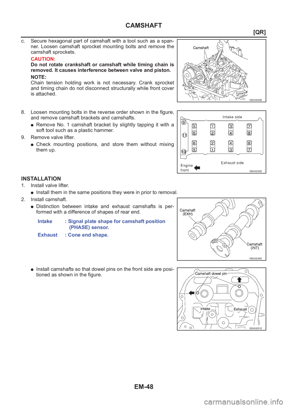
c. Secure hexagonal part of camshaft with a tool such as a span-
ner. Loosen camshaft sprocket mounting bolts and remove the
camshaft sprockets.
CAUTION:
Do not rotate crankshaft or camshaft while timing chain is
removed. It causes interference between valve and piston.
NOTE:
Chain tension holding work is not necessary. Crank sprocket
and timing chain do not disconnect structurally while front cover
is attached.
8. Loosen mounting bolts in the reverse order shown in the figure,
and remove camshaft brackets and camshafts.
●Remove No. 1 camshaft bracket by slightly tapping it with a
soft tool such as a plastic hammer.
9. Remove valve lifter.
●Check mounting positions, and store them without mixing
them up.
INSTALLATION
1. Install valve lifter.
●Install them in the same positions they were in prior to removal.
2. Install camshaft.
●Distinction between intake and exhaust camshafts is per-
formed with a difference of shapes of rear end.
●Install camshafts so that dowel pins on the front side are posi-
tioned as shown in the figure.
KBIA0049E
SBIA0255E
Intake : Signal plate shape for camshaft position
(PHASE) sensor.
Exhaust : Cone end shape.
KBIA0246E
KBIA0051E
Page 99 of 3833
CAMSHAFT
EM-49
[QR]
C
D
E
F
G
H
I
J
K
L
MA
EM
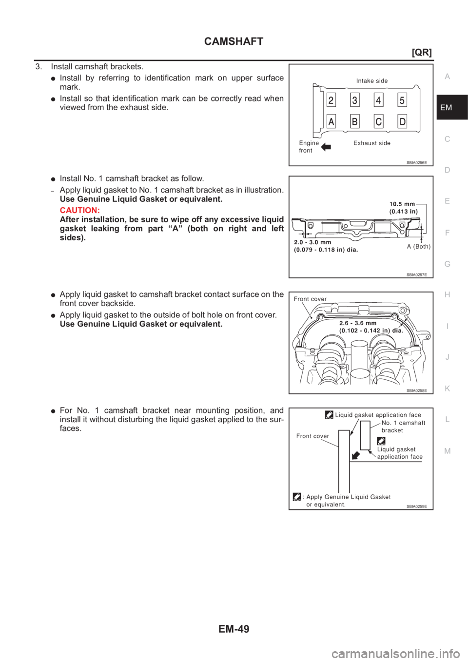
3. Install camshaft brackets.
●Install by referring to identification mark on upper surface
mark.
●Install so that identification mark can be correctly read when
viewed from the exhaust side.
●Install No. 1 camshaft bracket as follow.
–Apply liquid gasket to No. 1 camshaft bracket as in illustration.
Use Genuine Liquid Gasket or equivalent.
CAUTION:
After installation, be sure to wipe off any excessive liquid
gasket leaking from part “A” (both on right and left
sides).
●Apply liquid gasket to camshaft bracket contact surface on the
front cover backside.
●Apply liquid gasket to the outside of bolt hole on front cover.
Use Genuine Liquid Gasket or equivalent.
●For No. 1 camshaft bracket near mounting position, and
install it without disturbing the liquid gasket applied to the sur-
faces.
SBIA0256E
SBIA0257E
SBIA0258E
SBIA0259E
Page 100 of 3833
EM-50
[QR]
CAMSHAFT
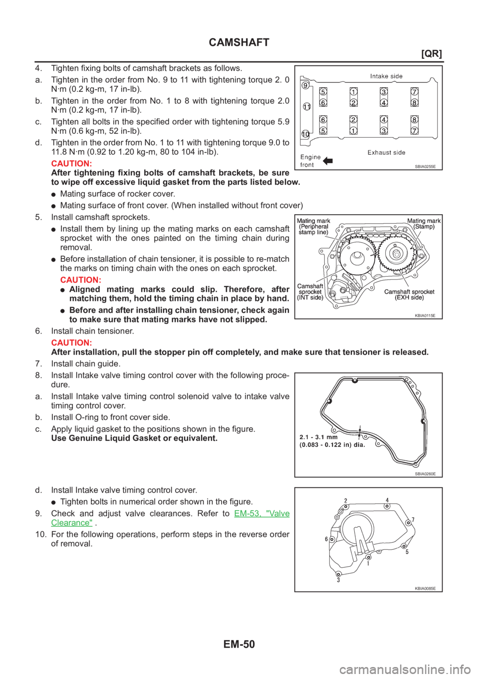
4. Tighten fixing bolts of camshaft brackets as follows.
a. Tighten in the order from No. 9 to 11 with tightening torque 2. 0
N·m (0.2 kg-m, 17 in-lb).
b. Tighten in the order from No. 1 to 8 with tightening torque 2.0
N·m (0.2 kg-m, 17 in-lb).
c. Tighten all bolts in the specified order with tightening torque 5.9
N·m (0.6 kg-m, 52 in-lb).
d. Tighten in the order from No. 1 to 11 with tightening torque 9.0 to
11.8 N·m (0.92 to 1.20 kg-m, 80 to 104 in-lb).
CAUTION:
After tightening fixing bolts of camshaft brackets, be sure
to wipe off excessive liquid gasket from the parts listed below.
●Mating surface of rocker cover.
●Mating surface of front cover. (When installed without front cover)
5. Install camshaft sprockets.
●Install them by lining up the mating marks on each camshaft
sprocket with the ones painted on the timing chain during
removal.
●Before installation of chain tensioner, it is possible to re-match
the marks on timing chain with the ones on each sprocket.
CAUTION:
●Aligned mating marks could slip. Therefore, after
matching them, hold the timing chain in place by hand.
●Before and after installing chain tensioner, check again
to make sure that mating marks have not slipped.
6. Install chain tensioner.
CAUTION:
After installation, pull the stopper pin off completely, and make sure that tensioner is released.
7. Install chain guide.
8. Install Intake valve timing control cover with the following proce-
dure.
a. Install Intake valve timing control solenoid valve to intake valve
timing control cover.
b. Install O-ring to front cover side.
c. Apply liquid gasket to the positions shown in the figure.
Use Genuine Liquid Gasket or equivalent.
d. Install Intake valve timing control cover.
●Tighten bolts in numerical order shown in the figure.
9. Check and adjust valve clearances. Refer to EM-53, "
Va l v e
Clearance" .
10. For the following operations, perform steps in the reverse order
of removal.
SBIA0255E
KBIA0115E
SBIA0260E
KBIA0085E
Page 101 of 3833
CAMSHAFT
EM-51
[QR]
C
D
E
F
G
H
I
J
K
L
MA
EM
INSPECTION AFTER REMOVAL
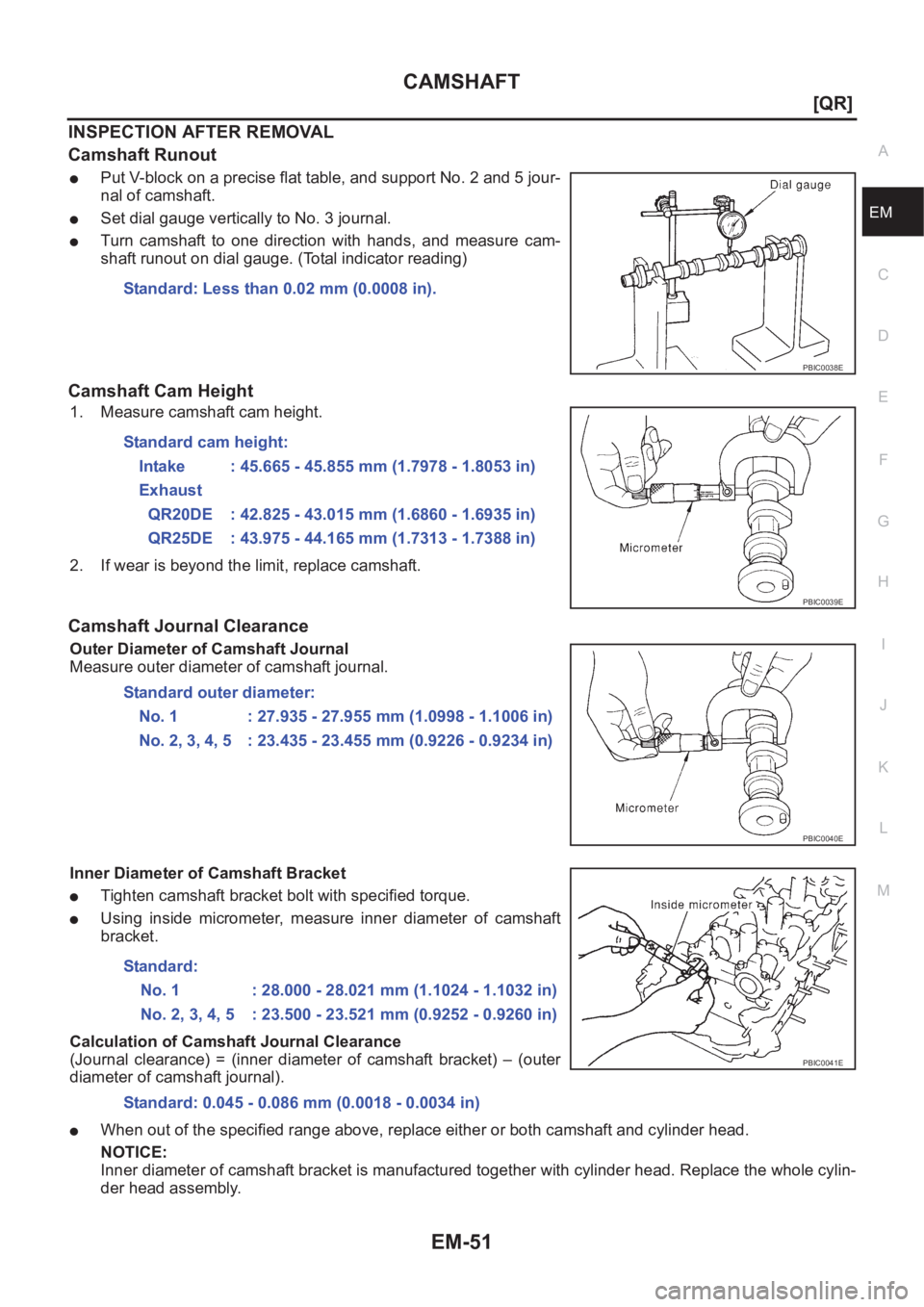
Camshaft Runout
●Put V-block on a precise flat table, and support No. 2 and 5 jour-
nal of camshaft.
●Set dial gauge vertically to No. 3 journal.
●Turn camshaft to one direction with hands, and measure cam-
shaft runout on dial gauge. (Total indicator reading)
Camshaft Cam Height
1. Measure camshaft cam height.
2. If wear is beyond the limit, replace camshaft.
Camshaft Journal Clearance
Outer Diameter of Camshaft Journal
Measure outer diameter of camshaft journal.
Inner Diameter of Camshaft Bracket
●Tighten camshaft bracket bolt with specified torque.
●Using inside micrometer, measure inner diameter of camshaft
bracket.
Calculation of Camshaft Journal Clearance
(Journal clearance) = (inner diameter of camshaft bracket) – (outer
diameter of camshaft journal).
●When out of the specified range above, replace either or both camshaft and cylinder head.
NOTICE:
Inner diameter of camshaft bracket is manufactured together with cylinder head. Replace the whole cylin-
der head assembly.Standard: Less than 0.02 mm (0.0008 in).
PBIC0038E
Standard cam height:
Intake : 45.665 - 45.855 mm (1.7978 - 1.8053 in)
Exhaust
QR20DE : 42.825 - 43.015 mm (1.6860 - 1.6935 in)
QR25DE : 43.975 - 44.165 mm (1.7313 - 1.7388 in)
PBIC0039E
Standard outer diameter:
No. 1 : 27.935 - 27.955 mm (1.0998 - 1.1006 in)
No. 2, 3, 4, 5 : 23.435 - 23.455 mm (0.9226 - 0.9234 in)
PBIC0040E
Standard:
No. 1 : 28.000 - 28.021 mm (1.1024 - 1.1032 in)
No. 2, 3, 4, 5 : 23.500 - 23.521 mm (0.9252 - 0.9260 in)
Standard: 0.045 - 0.086 mm (0.0018 - 0.0034 in)
PBIC0041E
Page 102 of 3833
EM-52
[QR]
CAMSHAFT
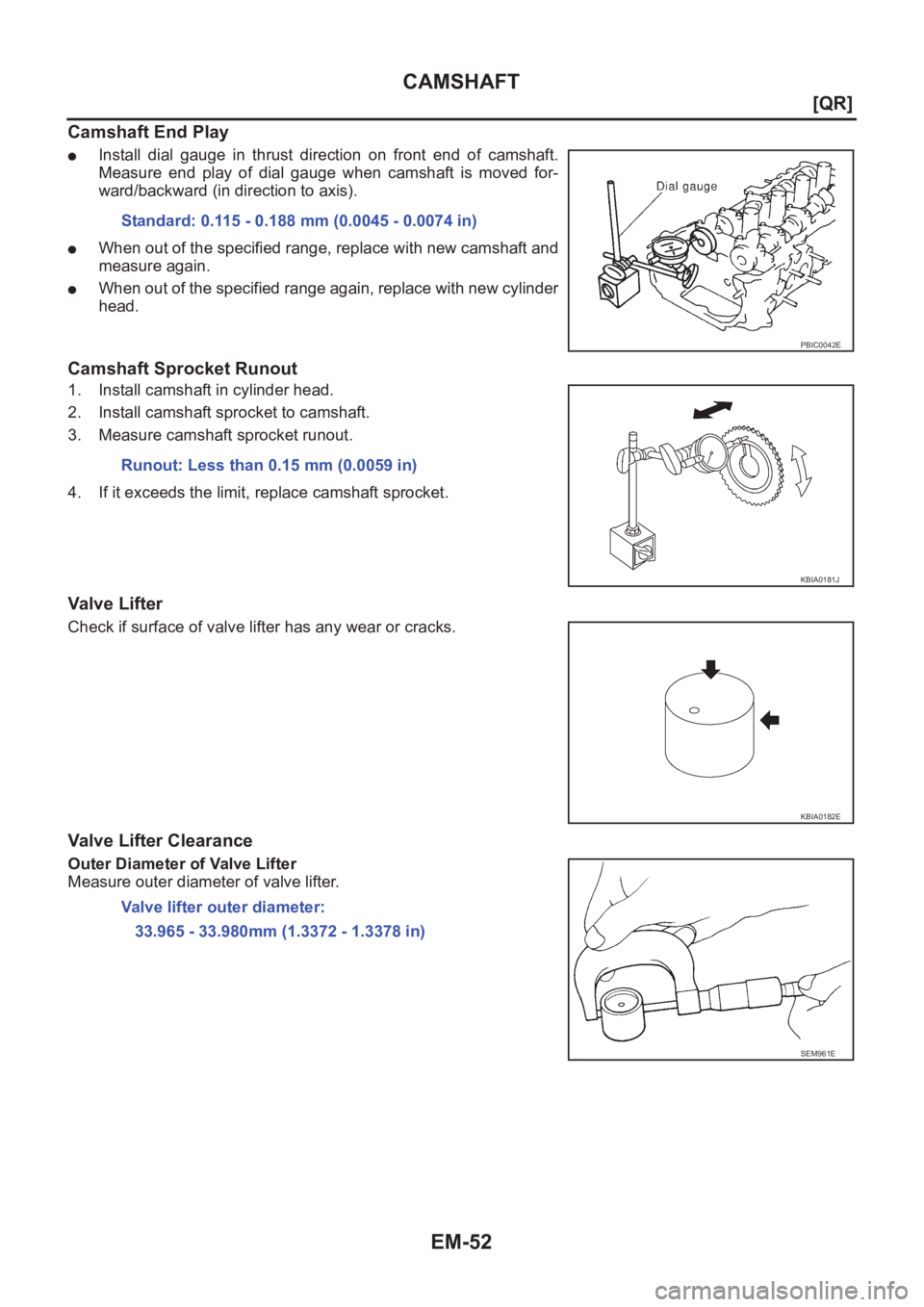
Camshaft End Play
●Install dial gauge in thrust direction on front end of camshaft.
Measure end play of dial gauge when camshaft is moved for-
ward/backward (in direction to axis).
●When out of the specified range, replace with new camshaft and
measure again.
●When out of the specified range again, replace with new cylinder
head.
Camshaft Sprocket Runout
1. Install camshaft in cylinder head.
2. Install camshaft sprocket to camshaft.
3. Measure camshaft sprocket runout.
4. If it exceeds the limit, replace camshaft sprocket.
Valve Lifter
Check if surface of valve lifter has any wear or cracks.
Valve Lifter Clearance
Outer Diameter of Valve Lifter
Measure outer diameter of valve lifter.Standard: 0.115 - 0.188 mm (0.0045 - 0.0074 in)
PBIC0042E
Runout: Less than 0.15 mm (0.0059 in)
KBIA0181J
KBIA0182E
Valve lifter outer diameter:
33.965 - 33.980mm (1.3372 - 1.3378 in)
SEM961E