Shaft NISSAN X-TRAIL 2001 Service Service Manual
[x] Cancel search | Manufacturer: NISSAN, Model Year: 2001, Model line: X-TRAIL, Model: NISSAN X-TRAIL 2001Pages: 3833, PDF Size: 39.49 MB
Page 125 of 3833
CYLINDER BLOCK
EM-75
[QR]
C
D
E
F
G
H
I
J
K
L
MA
EM
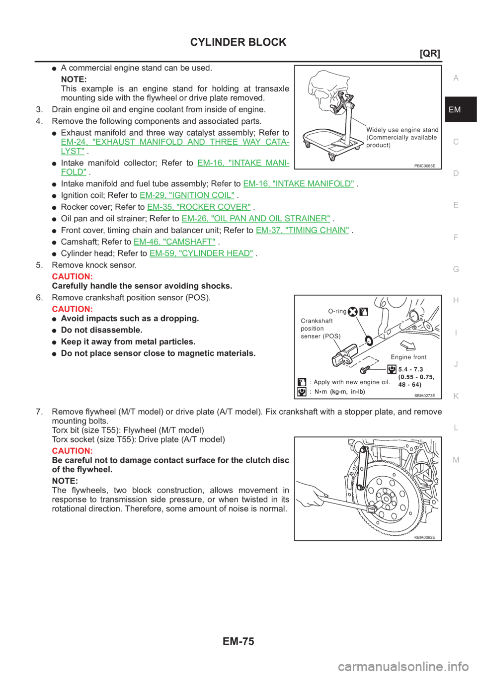
●A commercial engine stand can be used.
NOTE:
This example is an engine stand for holding at transaxle
mounting side with the flywheel or drive plate removed.
3. Drain engine oil and engine coolant from inside of engine.
4. Remove the following components and associated parts.
●Exhaust manifold and three way catalyst assembly; Refer to
EM-24, "
EXHAUST MANIFOLD AND THREE WAY CATA-
LYST" .
●Intake manifold collector; Refer to EM-16, "INTAKE MANI-
FOLD" .
●Intake manifold and fuel tube assembly; Refer to EM-16, "INTAKE MANIFOLD" .
●Ignition coil; Refer to EM-29, "IGNITION COIL" .
●Rocker cover; Refer to EM-35, "ROCKER COVER" .
●Oil pan and oil strainer; Refer to EM-26, "OIL PAN AND OIL STRAINER" .
●Front cover, timing chain and balancer unit; Refer to EM-37, "TIMING CHAIN" .
●Camshaft; Refer to EM-46, "CAMSHAFT" .
●Cylinder head; Refer to EM-59, "CYLINDER HEAD" .
5. Remove knock sensor.
CAUTION:
Carefully handle the sensor avoiding shocks.
6. Remove crankshaft position sensor (POS).
CAUTION:
●Avoid impacts such as a dropping.
●Do not disassemble.
●Keep it away from metal particles.
●Do not place sensor close to magnetic materials.
7. Remove flywheel (M/T model) or drive plate (A/T model). Fix crankshaft with a stopper plate, and remove
mounting bolts.
Torx bit (size T55): Flywheel (M/T model)
Torx socket (size T55): Drive plate (A/T model)
CAUTION:
Be careful not to damage contact surface for the clutch disc
of the flywheel.
NOTE:
The flywheels, two block construction, allows movement in
response to transmission side pressure, or when twisted in its
rotational direction. Therefore, some amount of noise is normal.
PBIC0085E
SBIA0273E
KBIA0062E
Page 126 of 3833
EM-76
[QR]
CYLINDER BLOCK
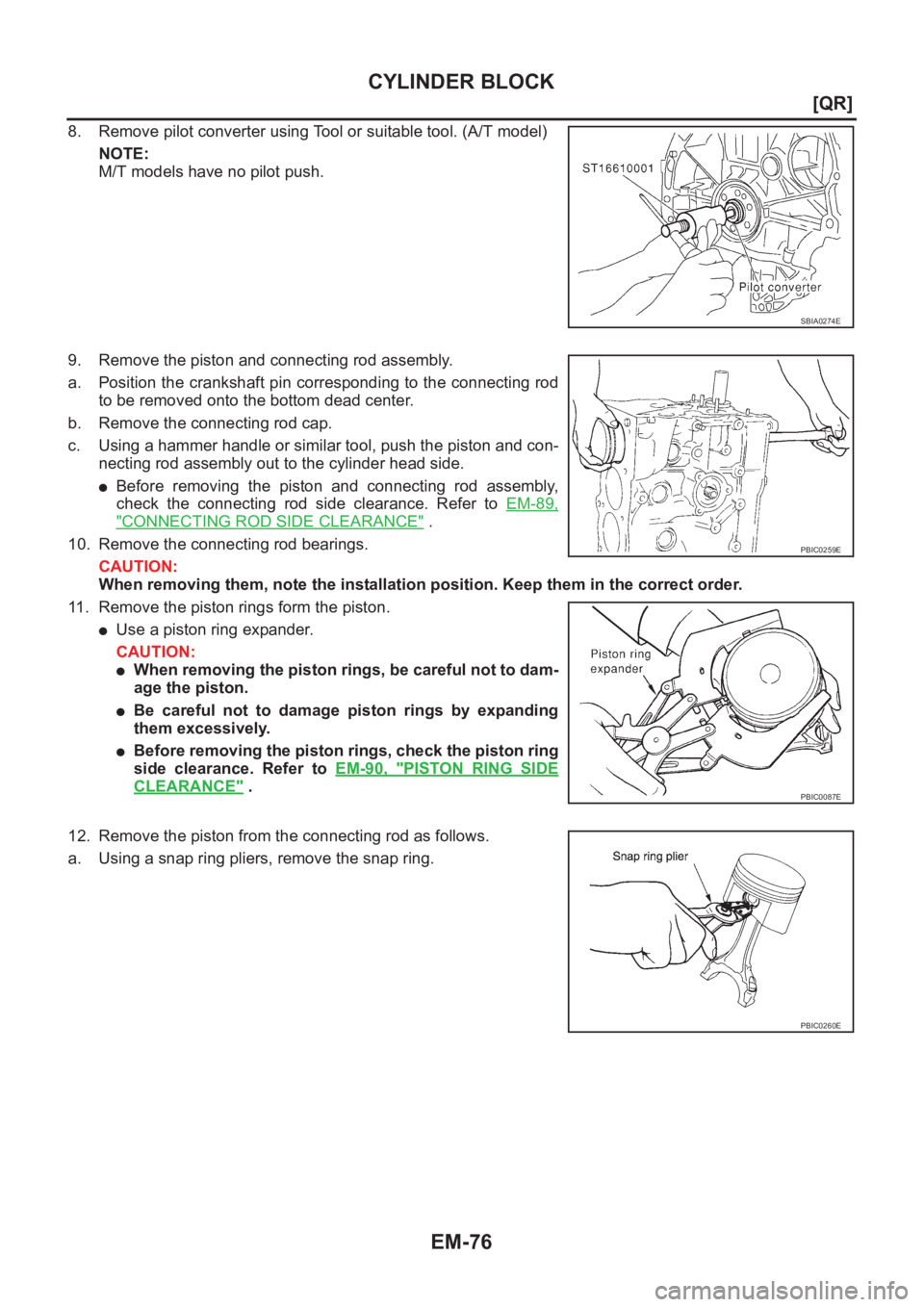
8. Remove pilot converter using Tool or suitable tool. (A/T model)
NOTE:
M/T models have no pilot push.
9. Remove the piston and connecting rod assembly.
a. Position the crankshaft pin corresponding to the connecting rod
to be removed onto the bottom dead center.
b. Remove the connecting rod cap.
c. Using a hammer handle or similar tool, push the piston and con-
necting rod assembly out to the cylinder head side.
●Before removing the piston and connecting rod assembly,
check the connecting rod side clearance. Refer to EM-89,
"CONNECTING ROD SIDE CLEARANCE" .
10. Remove the connecting rod bearings.
CAUTION:
When removing them, note the installation position. Keep them in the correct order.
11. Remove the piston rings form the piston.
●Use a piston ring expander.
CAUTION:
●When removing the piston rings, be careful not to dam-
age the piston.
●Be careful not to damage piston rings by expanding
them excessively.
●Before removing the piston rings, check the piston ring
side clearance. Refer to EM-90, "
PISTON RING SIDE
CLEARANCE" .
12. Remove the piston from the connecting rod as follows.
a. Using a snap ring pliers, remove the snap ring.
SBIA0274E
PBIC0259E
PBIC0087E
PBIC0260E
Page 127 of 3833
CYLINDER BLOCK
EM-77
[QR]
C
D
E
F
G
H
I
J
K
L
MA
EM
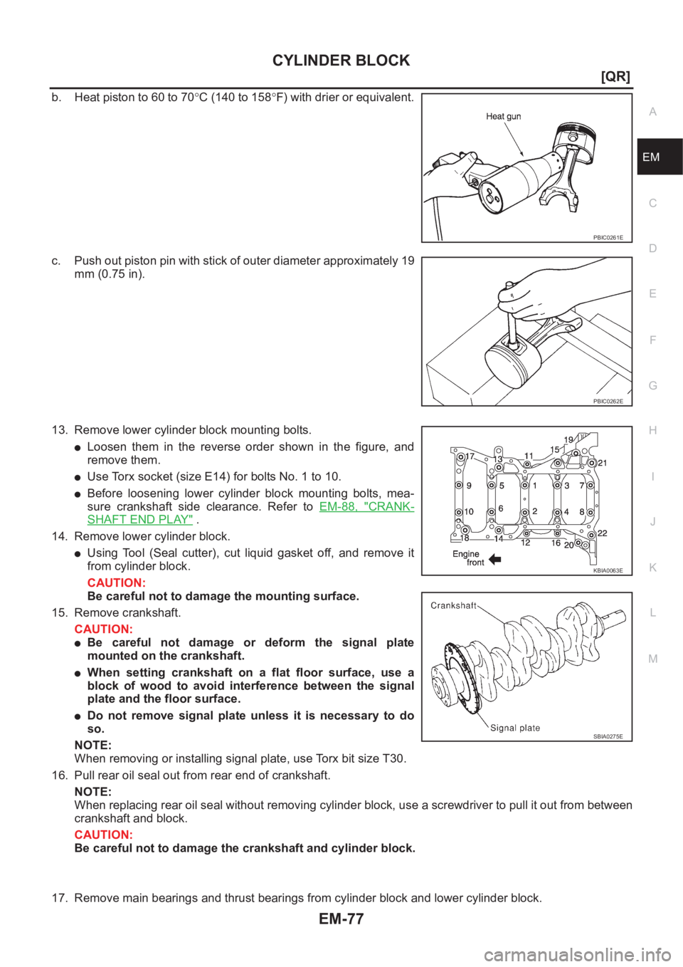
b. Heat piston to 60 to 70°C (140 to 158°F) with drier or equivalent.
c. Push out piston pin with stick of outer diameter approximately 19
mm (0.75 in).
13. Remove lower cylinder block mounting bolts.
●Loosen them in the reverse order shown in the figure, and
remove them.
●Use Torx socket (size E14) for bolts No. 1 to 10.
●Before loosening lower cylinder block mounting bolts, mea-
sure crankshaft side clearance. Refer to EM-88, "
CRANK-
SHAFT END PLAY" .
14. Remove lower cylinder block.
●Using Tool (Seal cutter), cut liquid gasket off, and remove it
from cylinder block.
CAUTION:
Be careful not to damage the mounting surface.
15. Remove crankshaft.
CAUTION:
●Be careful not damage or deform the signal plate
mounted on the crankshaft.
●When setting crankshaft on a flat floor surface, use a
block of wood to avoid interference between the signal
plate and the floor surface.
●Do not remove signal plate unless it is necessary to do
so.
NOTE:
When removing or installing signal plate, use Torx bit size T30.
16. Pull rear oil seal out from rear end of crankshaft.
NOTE:
When replacing rear oil seal without removing cylinder block, use a screwdriver to pull it out from between
crankshaft and block.
CAUTION:
Be careful not to damage the crankshaft and cylinder block.
17. Remove main bearings and thrust bearings from cylinder block and lower cylinder block.
PBIC0261E
PBIC0262E
KBIA0063E
SBIA0275E
Page 128 of 3833
EM-78
[QR]
CYLINDER BLOCK
CAUTION:
Identify installation positions, and store them without mixing them up.
ASSEMBLY
1. Fully air-blow the engine coolant and engine oil passages in the cylinder block, the cylinder bore and the
crankcase to remove any foreign material.
CAUTION:
Use a goggles to protect your eye.
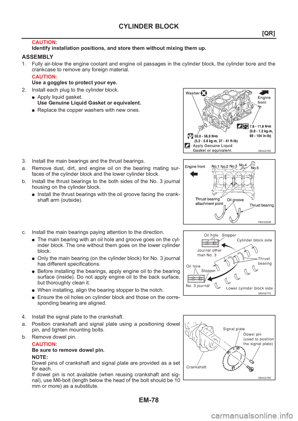
2. Install each plug to the cylinder block.
●Apply liquid gasket.
Use Genuine Liquid Gasket or equivalent.
●Replace the copper washers with new ones.
3. Install the main bearings and the thrust bearings.
a. Remove dust, dirt, and engine oil on the bearing mating sur-
faces of the cylinder block and the lower cylinder block.
b. Install the thrust bearings to the both sides of the No. 3 journal
housing on the cylinder block.
●Install the thrust bearings with the oil groove facing the crank-
shaft arm (outside).
c. Install the main bearings paying attention to the direction.
●The main bearing with an oil hole and groove goes on the cyl-
inder block. The one without them goes on the lower cylinder
block.
●Only the main bearing (on the cylinder block) for No. 3 journal
has different specifications.
●Before installing the bearings, apply engine oil to the bearing
surface (inside). Do not apply engine oil to the back surface,
but thoroughly clean it.
●When installing, align the bearing stopper to the notch.
●Ensure the oil holes on cylinder block and those on the corre-
sponding bearing are aligned.
4. Install the signal plate to the crankshaft.
a. Position crankshaft and signal plate using a positioning dowel
pin, and tighten mounting bolts.
b. Remove dowel pin.
CAUTION:
Be sure to remove dowel pin.
NOTE:
Dowel pins of crankshaft and signal plate are provided as a set
for each.
If dowel pin is not available (when reusing crankshaft and sig-
nal), use M6-bolt (length below the head of the bolt should be 10
mm or more) as a substitute.
SBIA0276E
PBIC0264E
SBIA0277E
SBIA0278E
Page 129 of 3833
CYLINDER BLOCK
EM-79
[QR]
C
D
E
F
G
H
I
J
K
L
MA
EM
5. Install the crankshaft to the cylinder block.
●While turning the crankshaft by hand, check that it turns smoothly.
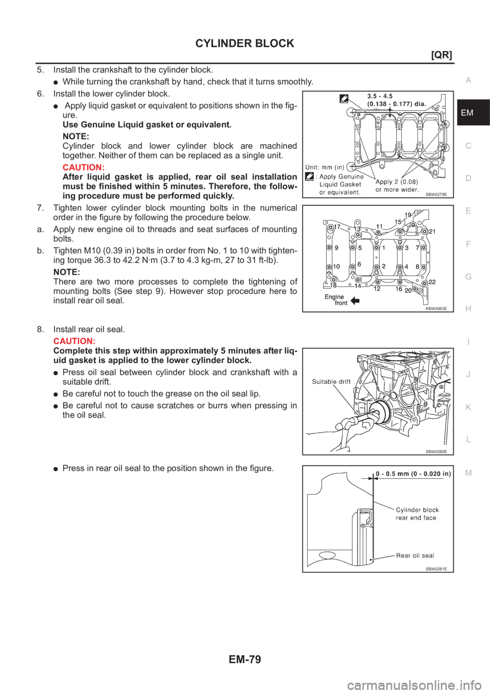
6. Install the lower cylinder block.
● Apply liquid gasket or equivalent to positions shown in the fig-
ure.
Use Genuine Liquid gasket or equivalent.
NOTE:
Cylinder block and lower cylinder block are machined
together. Neither of them can be replaced as a single unit.
CAUTION:
After liquid gasket is applied, rear oil seal installation
must be finished within 5 minutes. Therefore, the follow-
ing procedure must be performed quickly.
7. Tighten lower cylinder block mounting bolts in the numerical
order in the figure by following the procedure below.
a. Apply new engine oil to threads and seat surfaces of mounting
bolts.
b. Tighten M10 (0.39 in) bolts in order from No. 1 to 10 with tighten-
ing torque 36.3 to 42.2 N·m (3.7 to 4.3 kg-m, 27 to 31 ft-lb).
NOTE:
There are two more processes to complete the tightening of
mounting bolts (See step 9). However stop procedure here to
install rear oil seal.
8. Install rear oil seal.
CAUTION:
Complete this step within approximately 5 minutes after liq-
uid gasket is applied to the lower cylinder block.
●Press oil seal between cylinder block and crankshaft with a
suitable drift.
●Be careful not to touch the grease on the oil seal lip.
●Be careful not to cause scratches or burrs when pressing in
the oil seal.
●Press in rear oil seal to the position shown in the figure.
SBIA0279E
KBIA0063E
SBIA0280E
SBIA0281E
Page 130 of 3833
EM-80
[QR]
CYLINDER BLOCK
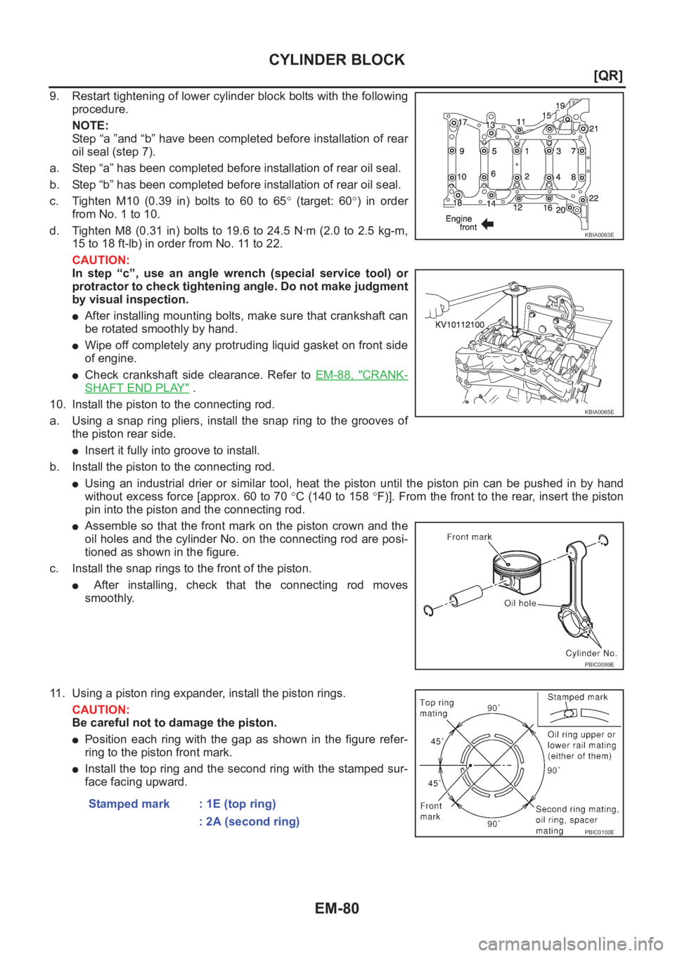
9. Restart tightening of lower cylinder block bolts with the following
procedure.
NOTE:
Step “a ”and “b” have been completed before installation of rear
oil seal (step 7).
a. Step “a” has been completed before installation of rear oil seal.
b. Step “b” has been completed before installation of rear oil seal.
c. Tighten M10 (0.39 in) bolts to 60 to 65° (target: 60°) in order
from No. 1 to 10.
d. Tighten M8 (0.31 in) bolts to 19.6 to 24.5 N·m (2.0 to 2.5 kg-m,
15 to 18 ft-lb) in order from No. 11 to 22.
CAUTION:
In step “c”, use an angle wrench (special service tool) or
protractor to check tightening angle. Do not make judgment
by visual inspection.
●After installing mounting bolts, make sure that crankshaft can
be rotated smoothly by hand.
●Wipe off completely any protruding liquid gasket on front side
of engine.
●Check crankshaft side clearance. Refer to EM-88, "CRANK-
SHAFT END PLAY" .
10. Install the piston to the connecting rod.
a. Using a snap ring pliers, install the snap ring to the grooves of
the piston rear side.
●Insert it fully into groove to install.
b. Install the piston to the connecting rod.
●Using an industrial drier or similar tool, heat the piston until the piston pin can be pushed in by hand
without excess force [approx. 60 to 70 °C (140 to 158 °F)]. From the front to the rear, insert the piston
pin into the piston and the connecting rod.
●Assemble so that the front mark on the piston crown and the
oil holes and the cylinder No. on the connecting rod are posi-
tioned as shown in the figure.
c. Install the snap rings to the front of the piston.
● After installing, check that the connecting rod moves
smoothly.
11. Using a piston ring expander, install the piston rings.
CAUTION:
Be careful not to damage the piston.
●Position each ring with the gap as shown in the figure refer-
ring to the piston front mark.
●Install the top ring and the second ring with the stamped sur-
face facing upward.
KBIA0063E
KBIA0065E
PBIC0099E
Stamped mark : 1E (top ring)
: 2A (second ring)
PBIC0100E
Page 131 of 3833
CYLINDER BLOCK
EM-81
[QR]
C
D
E
F
G
H
I
J
K
L
MA
EM
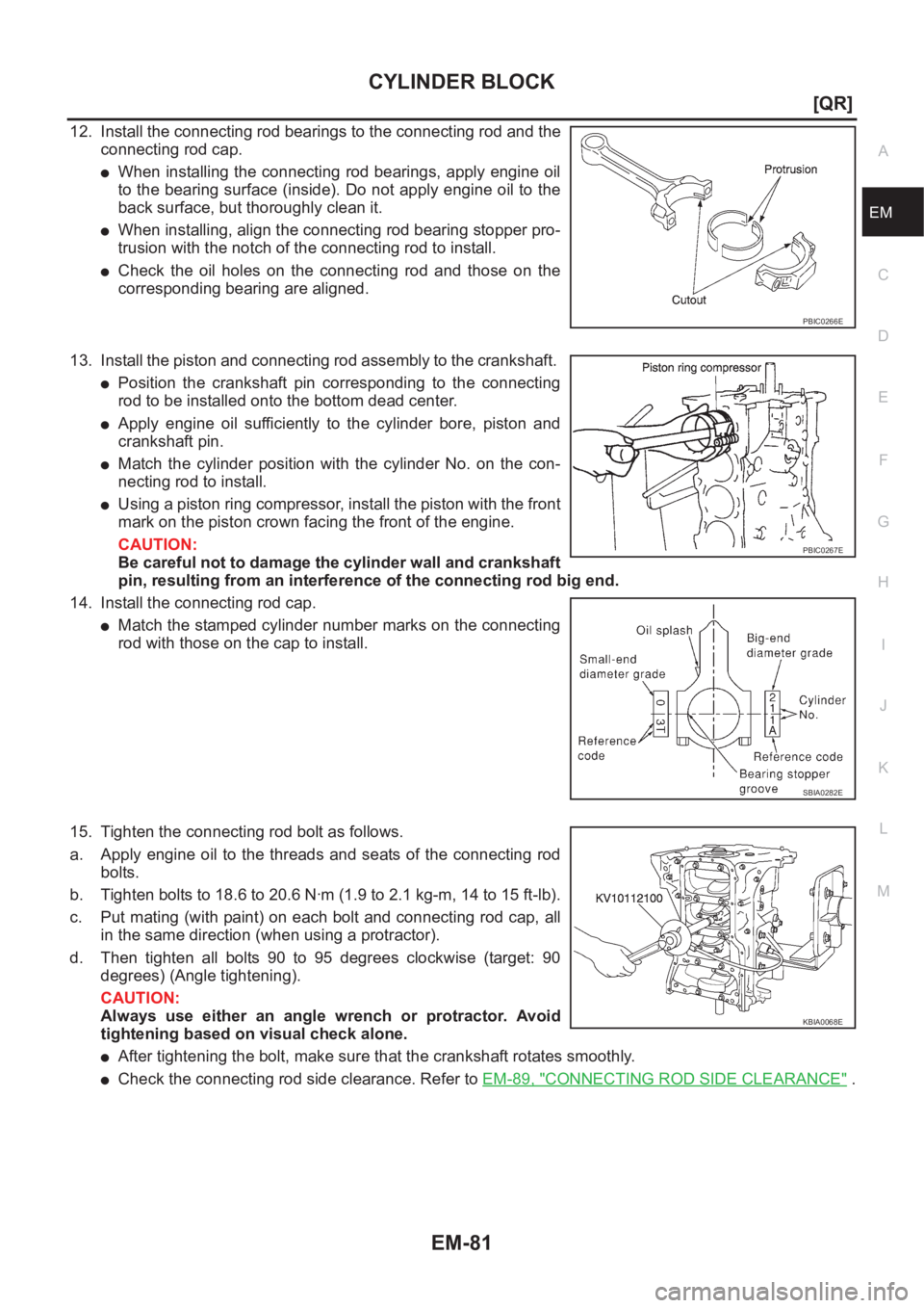
12. Install the connecting rod bearings to the connecting rod and the
connecting rod cap.
●When installing the connecting rod bearings, apply engine oil
to the bearing surface (inside). Do not apply engine oil to the
back surface, but thoroughly clean it.
●When installing, align the connecting rod bearing stopper pro-
trusion with the notch of the connecting rod to install.
●Check the oil holes on the connecting rod and those on the
corresponding bearing are aligned.
13. Install the piston and connecting rod assembly to the crankshaft.
●Position the crankshaft pin corresponding to the connecting
rod to be installed onto the bottom dead center.
●Apply engine oil sufficiently to the cylinder bore, piston and
crankshaft pin.
●Match the cylinder position with the cylinder No. on the con-
necting rod to install.
●Using a piston ring compressor, install the piston with the front
mark on the piston crown facing the front of the engine.
CAUTION:
Be careful not to damage the cylinder wall and crankshaft
pin, resulting from an interference of the connecting rod big end.
14. Install the connecting rod cap.
●Match the stamped cylinder number marks on the connecting
rod with those on the cap to install.
15. Tighten the connecting rod bolt as follows.
a. Apply engine oil to the threads and seats of the connecting rod
bolts.
b. Tighten bolts to 18.6 to 20.6 N·m (1.9 to 2.1 kg-m, 14 to 15 ft-lb).
c. Put mating (with paint) on each bolt and connecting rod cap, all
in the same direction (when using a protractor).
d. Then tighten all bolts 90 to 95 degrees clockwise (target: 90
degrees) (Angle tightening).
CAUTION:
Always use either an angle wrench or protractor. Avoid
tightening based on visual check alone.
●After tightening the bolt, make sure that the crankshaft rotates smoothly.
●Check the connecting rod side clearance. Refer to EM-89, "CONNECTING ROD SIDE CLEARANCE" .
PBIC0266E
PBIC0267E
SBIA0282E
KBIA0068E
Page 132 of 3833
EM-82
[QR]
CYLINDER BLOCK
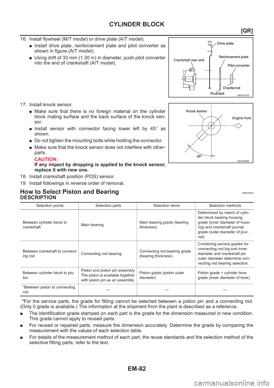
16. Install flywheel (M/T model) or drive plate (A/T model).
●Install drive plate, reinforcement plate and pilot converter as
shown in figure (A/T model).
●Using drift of 33 mm (1.30 in) in diameter, push pilot converter
into the end of crankshaft (A/T model).
17. Install knock sensor.
●Make sure that there is no foreign material on the cylinder
block mating surface and the back surface of the knock sen-
sor.
●Install sensor with connector facing lower left by 45° as
shown.
●D o n o t t i g h t e n t h e m o u n t i n g b o l t s w h i l e h o l d i n g t h e c o n n e c t o r.
●Make sure that the knock sensor does not interfere with other-
parts.
CAUTION:
If any impact by dropping is applied to the knock sensor,
replace it with new one.
18. Install crankshaft position (POS) sensor.
19. Install followings in reverse order of removal.
How to Select Piston and Bearing EBS00KNV
DESCRIPTION
*For the service parts, the grade for fitting cannot be selected between a piston pin and a connecting rod.
(Only 0 grade is available.) The information at the shipment from the plant is described as a reference.
●The identification grade stamped on each part is the grade for the dimension measured in new condition.
This grade cannot apply to reused parts.
●For reused or repaired parts, measure the dimension accurately. Determine the grade by comparing the
measurement with the values of each selection table.
●For details of the measurement method of each part, the reuse standards and the selection method of the
selective fitting parts, refer to the text.
KBIA0075E
KBIA0069E
Selection points Selection parts Selection items Selection methods
Between cylinder block to
crankshaftMain bearingMain bearing grade (bearing
thickness)Determined by match of cylin-
der block bearing housing
grade (inner diameter of hous-
ing) and crankshaft journal
grade (outer diameter of jour-
nal)
Between crankshaft to connect-
ing rodConnecting rod bearingConnecting rod bearing grade
(bearing thickness)Combining service grades for
connecting rod big end inner
diameter and crankshaft pin
outer diameter determine con-
necting rod bearing selection.
Between cylinder block to pis-
tonPiston and piston pin assembly
The piston is available together
with piston pin as an assembly.Piston grade (piston outer
diameter)Piston grade = cylinder bore
grade (inner diameter of bore)
*Between piston to connecting
rod———
Page 133 of 3833
CYLINDER BLOCK
EM-83
[QR]
C
D
E
F
G
H
I
J
K
L
MA
EM
HOW TO SELECT PISTON
When New Cylinder Block is Used:
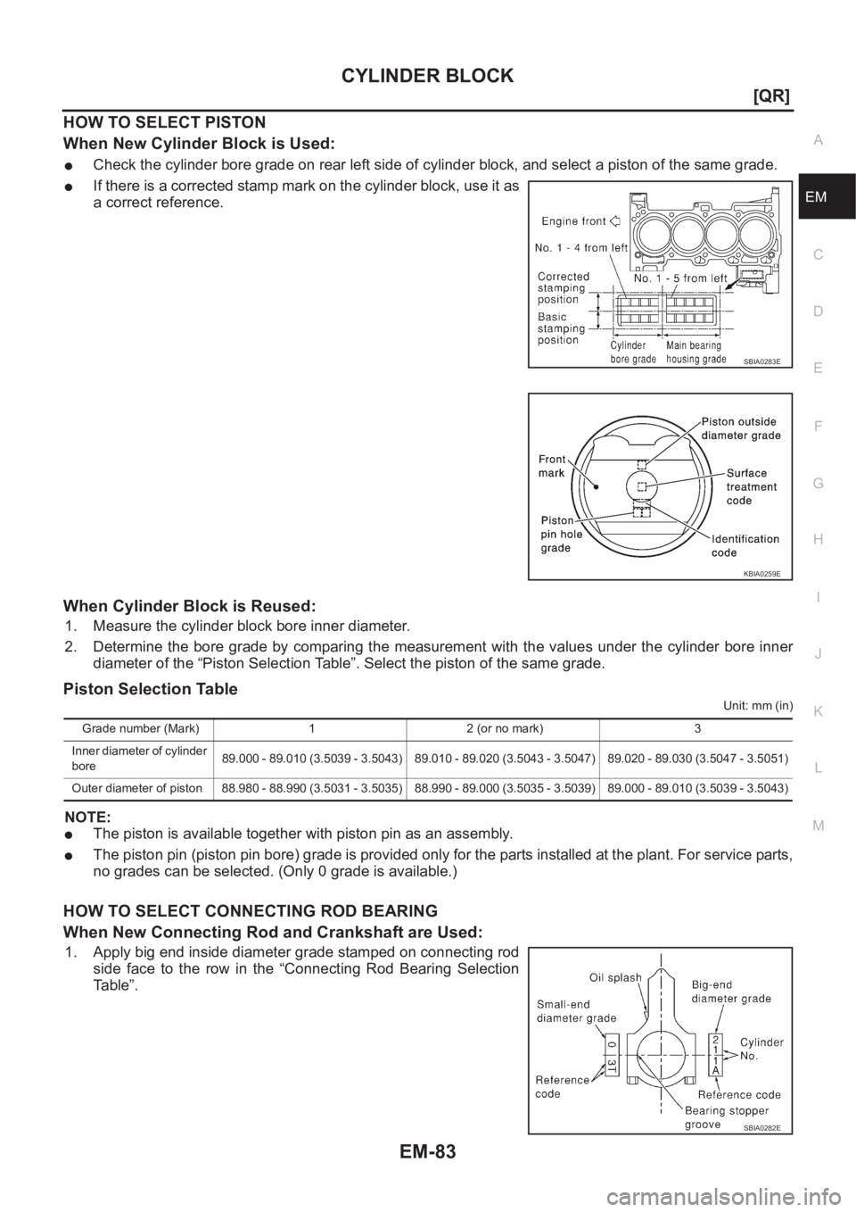
●Check the cylinder bore grade on rear left side of cylinder block, and select a piston of the same grade.
●If there is a corrected stamp mark on the cylinder block, use it as
a correct reference.
When Cylinder Block is Reused:
1. Measure the cylinder block bore inner diameter.
2. Determine the bore grade by comparing the measurement with the values under the cylinder bore inner
diameter of the “Piston Selection Table”. Select the piston of the same grade.
Piston Selection Table
Unit: mm (in)
NOTE:
●The piston is available together with piston pin as an assembly.
●The piston pin (piston pin bore) grade is provided only for the parts installed at the plant. For service parts,
no grades can be selected. (Only 0 grade is available.)
HOW TO SELECT CONNECTING ROD BEARING
When New Connecting Rod and Crankshaft are Used:
1. Apply big end inside diameter grade stamped on connecting rod
side face to the row in the “Connecting Rod Bearing Selection
Table”.
SBIA0283E
KBIA0259E
Grade number (Mark) 1 2 (or no mark) 3
Inner diameter of cylinder
bore89.000 - 89.010 (3.5039 - 3.5043) 89.010 - 89.020 (3.5043 - 3.5047) 89.020 - 89.030 (3.5047 - 3.5051)
Outer diameter of piston 88.980 - 88.990 (3.5031 - 3.5035) 88.990 - 89.000 (3.5035 - 3.5039) 89.000 - 89.010 (3.5039 - 3.5043)
SBIA0282E
Page 134 of 3833
EM-84
[QR]
CYLINDER BLOCK
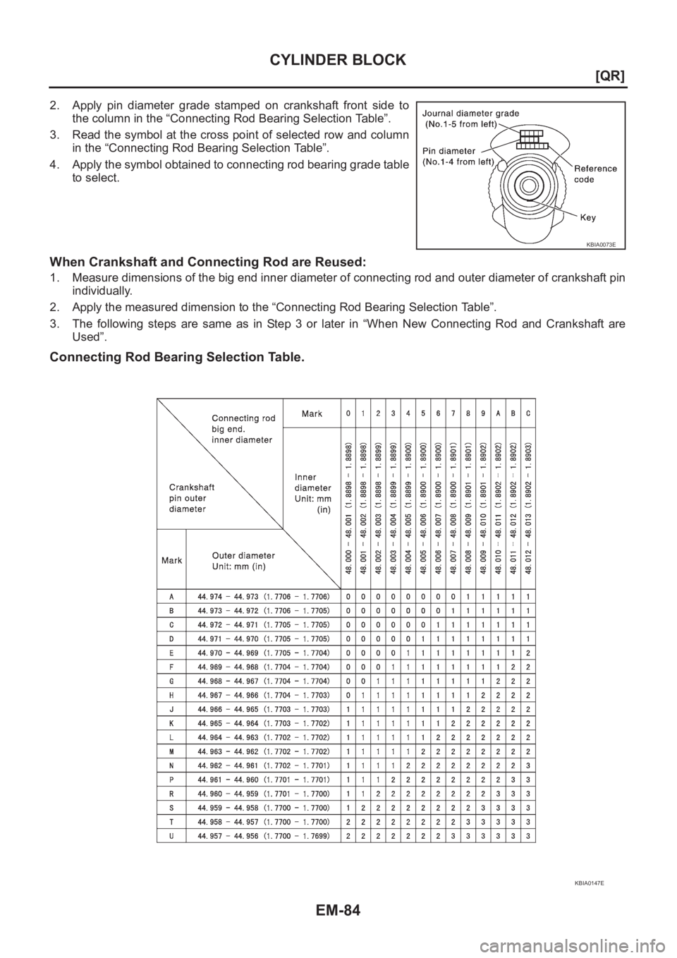
2. Apply pin diameter grade stamped on crankshaft front side to
the column in the “Connecting Rod Bearing Selection Table”.
3. Read the symbol at the cross point of selected row and column
in the “Connecting Rod Bearing Selection Table”.
4. Apply the symbol obtained to connecting rod bearing grade table
to select.
When Crankshaft and Connecting Rod are Reused:
1. Measure dimensions of the big end inner diameter of connecting rod and outer diameter of crankshaft pin
individually.
2. Apply the measured dimension to the “Connecting Rod Bearing Selection Table”.
3. The following steps are same as in Step 3 or later in “When New Connecting Rod and Crankshaft are
Used”.
Connecting Rod Bearing Selection Table.
KBIA0073E
KBIA0147E