change time NISSAN X-TRAIL 2001 Service Owner's Manual
[x] Cancel search | Manufacturer: NISSAN, Model Year: 2001, Model line: X-TRAIL, Model: NISSAN X-TRAIL 2001Pages: 3833, PDF Size: 39.49 MB
Page 533 of 3833
DTC P0134 HO2S1
EC-183
[QR25(WITH EURO-OBD)]
C
D
E
F
G
H
I
J
K
L
MA
EC
5.CHECK INTERMITTENT INCIDENT
Refer to EC-115, "
TROUBLE DIAGNOSIS FOR INTERMITTENT INCIDENT" .
>>INSPECTION END
Component InspectionEBS00M40
HEATED OXYGEN SENSOR 1
With CONSULT-II
1. Start engine and warm it up to normal operating temperature.
2. Select “MANU TRIG” and adjust “TRIGGER POINT” to 100% in “DATA MONITOR” mode with CONSULT-
II.
3. Select “HO2S1 (B1)” and “HO2S1 MNTR (B1)”.
4. Hold engine speed at 2,000 rpm under no load during the follow-
ing steps.
5. Touch “RECORD” on CONSULT-II screen.
6. Check the following.
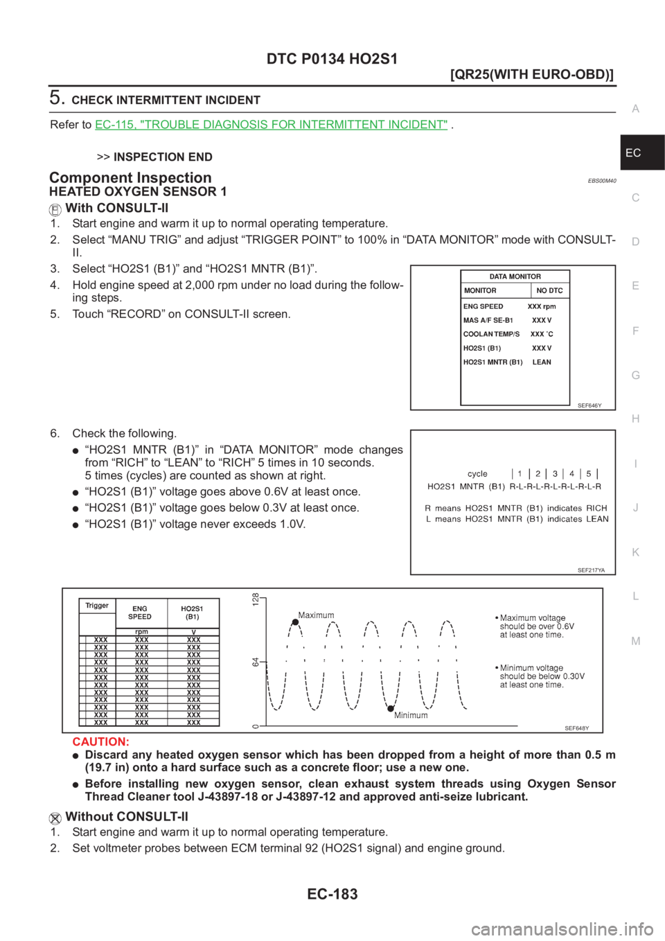
●“HO2S1 MNTR (B1)” in “DATA MONITOR” mode changes
from “RICH” to “LEAN” to “RICH” 5 times in 10 seconds.
5 times (cycles) are counted as shown at right.
●“HO2S1 (B1)” voltage goes above 0.6V at least once.
●“HO2S1 (B1)” voltage goes below 0.3V at least once.
●“HO2S1 (B1)” voltage never exceeds 1.0V.
CAUTION:
●Discard any heated oxygen sensor which has been dropped from a height of more than 0.5 m
(19.7 in) onto a hard surface such as a concrete floor; use a new one.
●Before installing new oxygen sensor, clean exhaust system threads using Oxygen Sensor
Thread Cleaner tool J-43897-18 or J-43897-12 and approved anti-seize lubricant.
Without CONSULT-II
1. Start engine and warm it up to normal operating temperature.
2. Set voltmeter probes between ECM terminal 92 (HO2S1 signal) and engine ground.
SEF646Y
SEF217YA
SEF648Y
Page 544 of 3833
EC-194
[QR25(WITH EURO-OBD)]
DTC P0139 HO2S2
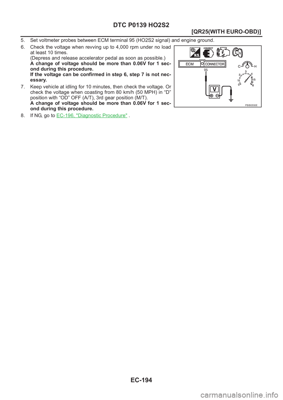
5. Set voltmeter probes between ECM terminal 95 (HO2S2 signal) and engine ground.
6. Check the voltage when revving up to 4,000 rpm under no load
at least 10 times.
(Depress and release accelerator pedal as soon as possible.)
A change of voltage should be more than 0.06V for 1 sec-
ond during this procedure.
If the voltage can be confirmed in step 6, step 7 is not nec-
essary.
7. Keep vehicle at idling for 10 minutes, then check the voltage. Or
check the voltage when coasting from 80 km/h (50 MPH) in “D”
position with “OD” OFF (A/T), 3rd gear position (M/T).
A change of voltage should be more than 0.06V for 1 sec-
ond during this procedure.
8. If NG, go to EC-196, "
Diagnostic Procedure" .
PBIB0550E
Page 645 of 3833
DTC P1143 HO2S1
EC-295
[QR25(WITH EURO-OBD)]
C
D
E
F
G
H
I
J
K
L
MA
EC
DTC P1143 HO2S1PFP:22690
Component DescriptionEBS00M7X
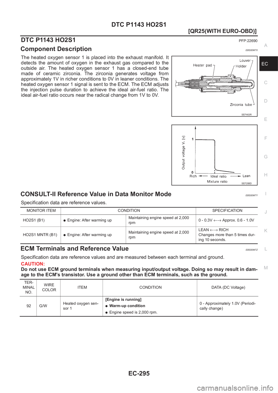
The heated oxygen sensor 1 is placed into the exhaust manifold. It
detects the amount of oxygen in the exhaust gas compared to the
outside air. The heated oxygen sensor 1 has a closed-end tube
made of ceramic zirconia. The zirconia generates voltage from
approximately 1V in richer conditions to 0V in leaner conditions. The
heated oxygen sensor 1 signal is sent to the ECM. The ECM adjusts
the injection pulse duration to achieve the ideal air-fuel ratio. The
ideal air-fuel ratio occurs near the radical change from 1V to 0V.
CONSULT-II Reference Value in Data Monitor ModeEBS00M7Y
Specification data are reference values.
ECM Terminals and Reference ValueEBS00M7Z
Specification data are reference values and are measured between each terminal and ground.
CAUTION:
Do not use ECM ground terminals when measuring input/output voltage. Doing so may result in dam-
age to the ECM's transistor. Use a ground other than ECM terminals, such as the ground.
SEF463R
SEF288D
MONITOR ITEM CONDITION SPECIFICATION
HO2S1 (B1)
●Engine: After warming upMaintaining engine speed at 2,000
rpm0 - 0.3V ←→ Approx. 0.6 - 1.0V
HO2S1 MNTR (B1)
●Engine: After warming upMaintaining engine speed at 2,000
rpmLEAN←→ RICH
Changes more than 5 times dur-
ing 10 seconds.
TER-
MINAL
NO.WIRE
COLORITEM CONDITION DATA (DC Voltage)
92 G/WHeated oxygen sen-
sor 1[Engine is running]
●Warm-up condition
●Engine speed is 2,000 rpm.0 - Approximately 1.0V (Periodi-
cally change)
Page 647 of 3833
DTC P1143 HO2S1
EC-297
[QR25(WITH EURO-OBD)]
C
D
E
F
G
H
I
J
K
L
MA
EC
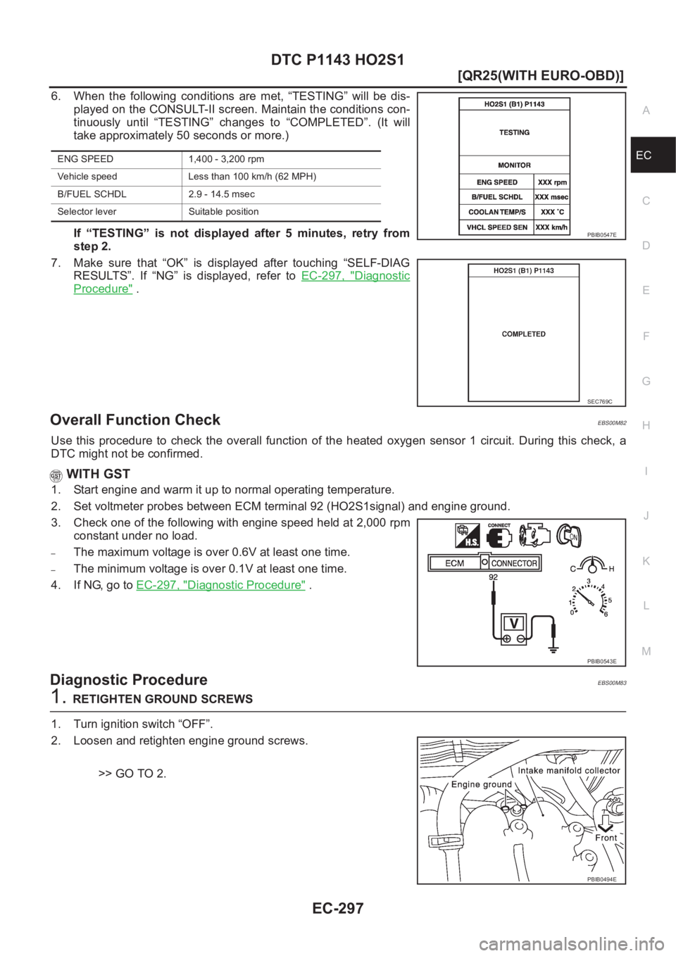
6. When the following conditions are met, “TESTING” will be dis-
played on the CONSULT-II screen. Maintain the conditions con-
tinuously until “TESTING” changes to “COMPLETED”. (It will
take approximately 50 seconds or more.)
If “TESTING” is not displayed after 5 minutes, retry from
step 2.
7. Make sure that “OK” is displayed after touching “SELF-DIAG
RESULTS”. If “NG” is displayed, refer to EC-297, "
Diagnostic
Procedure" .
Overall Function CheckEBS00M82
Use this procedure to check the overall function of the heated oxygen sensor 1 circuit. During this check, a
DTC might not be confirmed.
WITH GST
1. Start engine and warm it up to normal operating temperature.
2. Set voltmeter probes between ECM terminal 92 (HO2S1signal) and engine ground.
3. Check one of the following with engine speed held at 2,000 rpm
constant under no load.
–The maximum voltage is over 0.6V at least one time.
–The minimum voltage is over 0.1V at least one time.
4. If NG, go to EC-297, "
Diagnostic Procedure" .
Diagnostic ProcedureEBS00M83
1.RETIGHTEN GROUND SCREWS
1. Turn ignition switch “OFF”.
2. Loosen and retighten engine ground screws.
>> GO TO 2.
ENG SPEED 1,400 - 3,200 rpm
Vehicle speed Less than 100 km/h (62 MPH)
B/FUEL SCHDL 2.9 - 14.5 msec
Selector lever Suitable position
PBIB0547E
SEC769C
PBIB0543E
PBIB0494E
Page 649 of 3833
DTC P1143 HO2S1
EC-299
[QR25(WITH EURO-OBD)]
C
D
E
F
G
H
I
J
K
L
MA
EC
5.CHECK HEATED OXYGEN SENSOR 1
Refer to EC-299, "
Component Inspection" .
OK or NG
OK >> GO TO 6.
NG >> Replace heated oxygen sensor 1.
6.CHECK INTERMITTENT INCIDENT
Refer to EC-115, "
TROUBLE DIAGNOSIS FOR INTERMITTENT INCIDENT" .
For circuit, refer to EC-165, "
Wiring Diagram" .
>>INSPECTION END
Component InspectionEBS00M84
HEATED OXYGEN SENSOR 1
With CONSULT-II
1. Start engine and warm it up to normal operating temperature.
2. Select “MANU TRIG” and adjust “TRIGGER POINT” to 100% in “DATA MONITOR” mode with CONSULT-
II.
3. Select “HO2S1 (B1)” and “HO2S1 MNTR (B1)”.
4. Hold engine speed at 2,000 rpm under no load during the follow-
ing steps.
5. Touch “RECORD” on CONSULT-II screen.
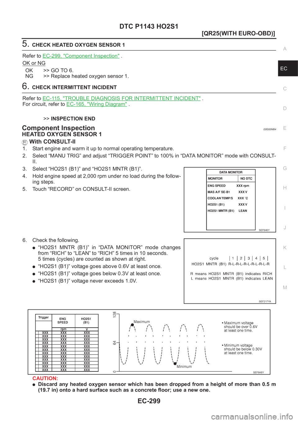
6. Check the following.
●“HO2S1 MNTR (B1)” in “DATA MONITOR” mode changes
from “RICH” to “LEAN” to “RICH” 5 times in 10 seconds.
5 times (cycles) are counted as shown at right.
●“HO2S1 (B1)” voltage goes above 0.6V at least once.
●“HO2S1 (B1)” voltage goes below 0.3V at least once.
●“HO2S1 (B1)” voltage never exceeds 1.0V.
CAUTION:
●Discard any heated oxygen sensor which has been dropped from a height of more than 0.5 m
(19.7 in) onto a hard surface such as a concrete floor; use a new one.
SEF646Y
SEF217YA
SEF648Y
Page 651 of 3833
DTC P1144 HO2S1
EC-301
[QR25(WITH EURO-OBD)]
C
D
E
F
G
H
I
J
K
L
MA
EC
DTC P1144 HO2S1PFP:22690
Component DescriptionEBS00M86
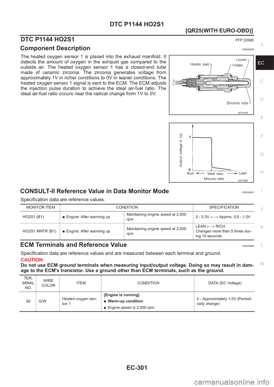
The heated oxygen sensor 1 is placed into the exhaust manifold. It
detects the amount of oxygen in the exhaust gas compared to the
outside air. The heated oxygen sensor 1 has a closed-end tube
made of ceramic zirconia. The zirconia generates voltage from
approximately 1V in richer conditions to 0V in leaner conditions. The
heated oxygen sensor 1 signal is sent to the ECM. The ECM adjusts
the injection pulse duration to achieve the ideal air-fuel ratio. The
ideal air-fuel ratio occurs near the radical change from 1V to 0V.
CONSULT-II Reference Value in Data Monitor ModeEBS00M87
Specification data are reference values.
ECM Terminals and Reference ValueEBS00M88
Specification data are reference values and are measured between each terminal and ground.
CAUTION:
Do not use ECM ground terminals when measuring input/output voltage. Doing so may result in dam-
age to the ECM's transistor. Use a ground other than ECM terminals, such as the ground.
SEF463R
SEF288D
MONITOR ITEM CONDITION SPECIFICATION
HO2S1 (B1)
●Engine: After warming upMaintaining engine speed at 2,000
rpm0 - 0.3V ←→ Approx. 0.6 - 1.0V
HO2S1 MNTR (B1)
●Engine: After warming upMaintaining engine speed at 2,000
rpmLEAN←→ RICH
Changes more than 5 times dur-
ing 10 seconds.
TER-
MINAL
NO.WIRE
COLORITEM CONDITION DATA (DC Voltage)
92 G/WHeated oxygen sen-
sor 1[Engine is running]
●Warm-up condition
●Engine speed is 2,000 rpm.0 - Approximately 1.0V (Periodi-
cally change)
Page 653 of 3833
DTC P1144 HO2S1
EC-303
[QR25(WITH EURO-OBD)]
C
D
E
F
G
H
I
J
K
L
MA
EC
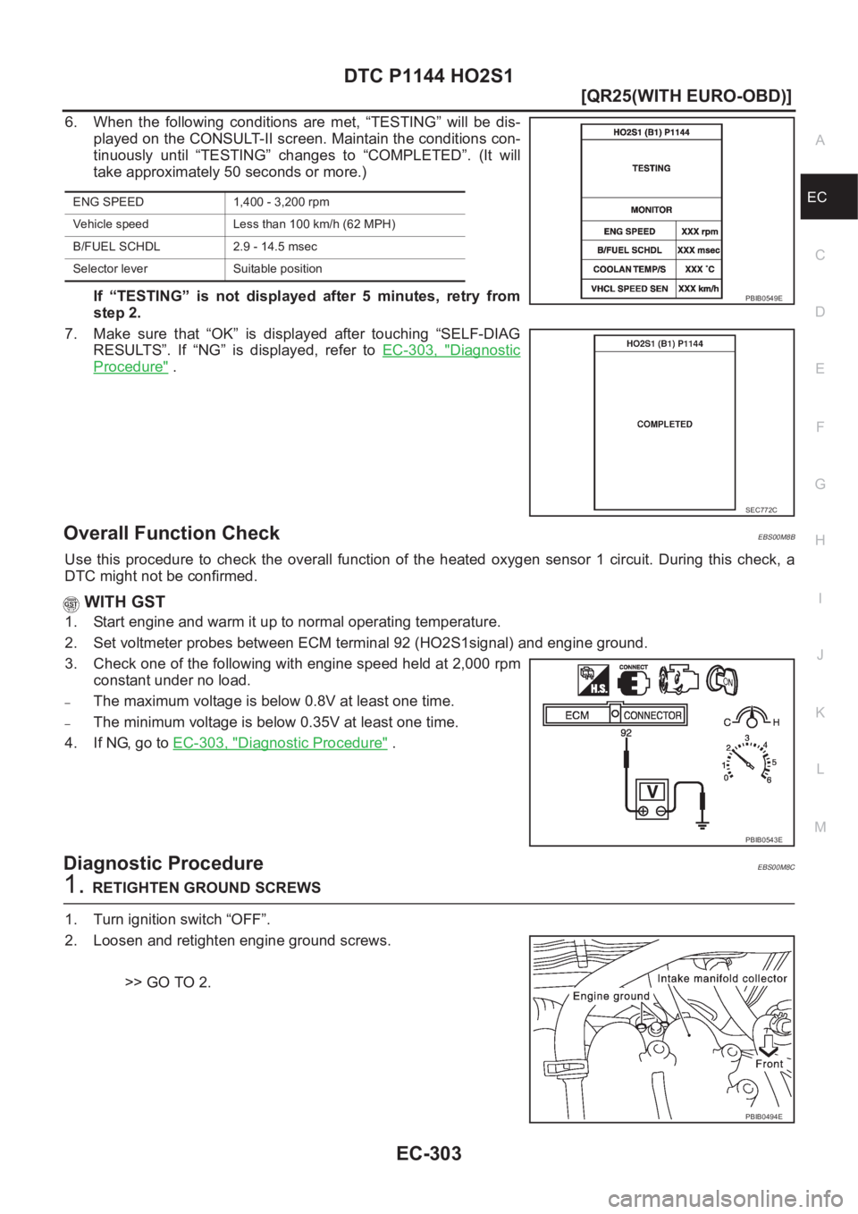
6. When the following conditions are met, “TESTING” will be dis-
played on the CONSULT-II screen. Maintain the conditions con-
tinuously until “TESTING” changes to “COMPLETED”. (It will
take approximately 50 seconds or more.)
If “TESTING” is not displayed after 5 minutes, retry from
step 2.
7. Make sure that “OK” is displayed after touching “SELF-DIAG
RESULTS”. If “NG” is displayed, refer to EC-303, "
Diagnostic
Procedure" .
Overall Function CheckEBS00M8B
Use this procedure to check the overall function of the heated oxygen sensor 1 circuit. During this check, a
DTC might not be confirmed.
WITH GST
1. Start engine and warm it up to normal operating temperature.
2. Set voltmeter probes between ECM terminal 92 (HO2S1signal) and engine ground.
3. Check one of the following with engine speed held at 2,000 rpm
constant under no load.
–The maximum voltage is below 0.8V at least one time.
–The minimum voltage is below 0.35V at least one time.
4. If NG, go to EC-303, "
Diagnostic Procedure" .
Diagnostic ProcedureEBS00M8C
1.RETIGHTEN GROUND SCREWS
1. Turn ignition switch “OFF”.
2. Loosen and retighten engine ground screws.
>> GO TO 2.
ENG SPEED 1,400 - 3,200 rpm
Vehicle speed Less than 100 km/h (62 MPH)
B/FUEL SCHDL 2.9 - 14.5 msec
Selector lever Suitable position
PBIB0549E
SEC772C
PBIB0543E
PBIB0494E
Page 656 of 3833
EC-306
[QR25(WITH EURO-OBD)]
DTC P1144 HO2S1
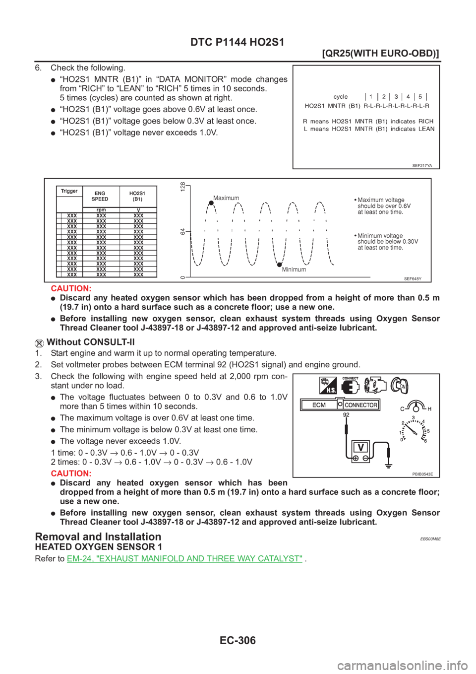
6. Check the following.
●“HO2S1 MNTR (B1)” in “DATA MONITOR” mode changes
from “RICH” to “LEAN” to “RICH” 5 times in 10 seconds.
5 times (cycles) are counted as shown at right.
●“HO2S1 (B1)” voltage goes above 0.6V at least once.
●“HO2S1 (B1)” voltage goes below 0.3V at least once.
●“HO2S1 (B1)” voltage never exceeds 1.0V.
CAUTION:
●Discard any heated oxygen sensor which has been dropped from a height of more than 0.5 m
(19.7 in) onto a hard surface such as a concrete floor; use a new one.
●Before installing new oxygen sensor, clean exhaust system threads using Oxygen Sensor
Thread Cleaner tool J-43897-18 or J-43897-12 and approved anti-seize lubricant.
Without CONSULT-II
1. Start engine and warm it up to normal operating temperature.
2. Set voltmeter probes between ECM terminal 92 (HO2S1 signal) and engine ground.
3. Check the following with engine speed held at 2,000 rpm con-
stant under no load.
●The voltage fluctuates between 0 to 0.3V and 0.6 to 1.0V
more than 5 times within 10 seconds.
●The maximum voltage is over 0.6V at least one time.
●The minimum voltage is below 0.3V at least one time.
●The voltage never exceeds 1.0V.
1 time: 0 - 0.3V → 0.6 - 1.0V → 0 - 0.3V
2 times: 0 - 0.3V → 0.6 - 1.0V → 0 - 0.3V → 0.6 - 1.0V
CAUTION:
●Discard any heated oxygen sensor which has been
dropped from a height of more than 0.5 m (19.7 in) onto a hard surface such as a concrete floor;
use a new one.
●Before installing new oxygen sensor, clean exhaust system threads using Oxygen Sensor
Thread Cleaner tool J-43897-18 or J-43897-12 and approved anti-seize lubricant.
Removal and InstallationEBS00M8E
HEATED OXYGEN SENSOR 1
Refer to EM-24, "EXHAUST MANIFOLD AND THREE WAY CATALYST" .
SEF217YA
SEF648Y
PBIB0543E
Page 795 of 3833
ENGINE CONTROL SYSTEM
EC-445
[QR25(WITHOUT EURO-OBD)]
C
D
E
F
G
H
I
J
K
L
MA
EC
inally designed. Both manufacturing differences (i.e., mass air flow sensor hot film) and characteristic changes
during operation (i.e., injector clogging) directly affect mixture ratio.
Accordingly, the difference between the basic and theoretical mixture ratios is monitored in this system. This is
then computed in terms of “injection pulse duration” to automatically compensate for the difference between
the two ratios.
“Fuel trim” refers to the feedback compensation value compared against the basic injection duration. Fuel trim
includes short term fuel trim and long term fuel trim.
“Short term fuel trim” is the short-term fuel compensation used to maintain the mixture ratio at its theoretical
value. The signal from heated oxygen sensor 1 indicates whether the mixture ratio is RICH or LEAN compared
to the theoretical value. The signal then triggers a reduction in fuel volume if the mixture ratio is rich, and an
increase in fuel volume if it is lean.
“Long term fuel trim” is overall fuel compensation carried out long-term to compensate for continual deviation
of the short term fuel trim from the central value. Such deviation will occur due to individual engine differences,
wear over time and changes in the usage environment.
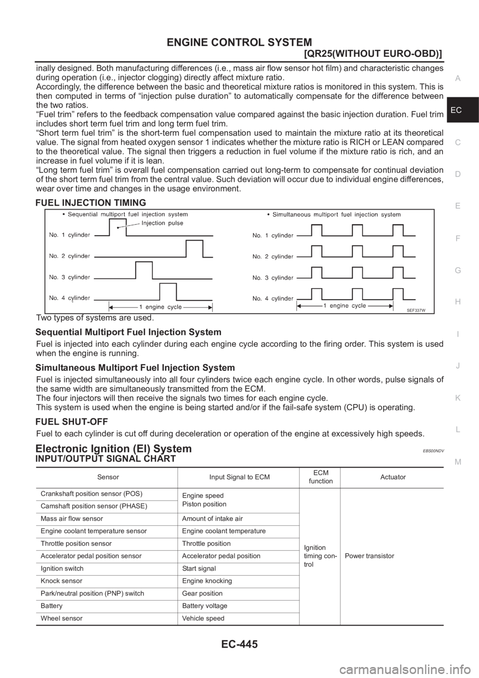
FUEL INJECTION TIMING
Two types of systems are used.
Sequential Multiport Fuel Injection System
Fuel is injected into each cylinder during each engine cycle according to the firing order. This system is used
when the engine is running.
Simultaneous Multiport Fuel Injection System
Fuel is injected simultaneously into all four cylinders twice each engine cycle. In other words, pulse signals of
the same width are simultaneously transmitted from the ECM.
The four injectors will then receive the signals two times for each engine cycle.
This system is used when the engine is being started and/or if the fail-safe system (CPU) is operating.
FUEL SHUT-OFF
Fuel to each cylinder is cut off during deceleration or operation of the engine at excessively high speeds.
Electronic Ignition (EI) SystemEBS00NDV
INPUT/OUTPUT SIGNAL CHART
SEF337W
Sensor Input Signal to ECMECM
functionActuator
Crankshaft position sensor (POS)
Engine speed
Piston position
Ignition
timing con-
trolPower transistor Camshaft position sensor (PHASE)
Mass air flow sensor Amount of intake air
Engine coolant temperature sensor Engine coolant temperature
Throttle position sensor Throttle position
Accelerator pedal position sensor Accelerator pedal position
Ignition switch Start signal
Knock sensor Engine knocking
Park/neutral position (PNP) switch Gear position
Battery Battery voltage
Wheel sensor Vehicle speed
Page 809 of 3833
ON BOARD DIAGNOSTIC (OBD) SYSTEM
EC-459
[QR25(WITHOUT EURO-OBD)]
C
D
E
F
G
H
I
J
K
L
MA
EC
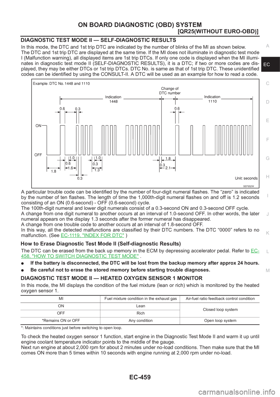
DIAGNOSTIC TEST MODE II — SELF-DIAGNOSTIC RESULTS
In this mode, the DTC and 1st trip DTC are indicated by the number of blinks of the MI as shown below.
The DTC and 1st trip DTC are displayed at the same time. If the MI does not illuminate in diagnostic test mode
I (Malfunction warning), all displayed items are 1st trip DTCs. If only one code is displayed when the MI illumi-
nates in diagnostic test mode II (SELF-DIAGNOSTIC RESULTS), it is a DTC; if two or more codes are dis-
played, they may be either DTCs or 1st trip DTCs. DTC No. is same as that of 1st trip DTC. These unidentified
codes can be identified by using the CONSULT-II. A DTC will be used as an example for how to read a code.
A particular trouble code can be identified by the number of four-digit numeral flashes. The “zero” is indicated
by the number of ten flashes. The length of time the 1,000th-digit numeral flashes on and off is 1.2 seconds
consisting of an ON (0.6-second) - OFF (0.6-second) cycle.
The 100th-digit numeral and lower digit numerals consist of a 0.3-second ON and 0.3-second OFF cycle.
A change from one digit numeral to another occurs at an interval of 1.0-second OFF. In other words, the later
numeral appears on the display 1.3 seconds after the former numeral has disappeared.
A change from one trouble code to another occurs at an interval of 1.8-second OFF.
In this way, all the detected malfunctions are classified by their DTC numbers. The DTC “0000” refers to no
malfunction. (See E C - 111 9 , "
INDEX FOR DTC" )
How to Erase Diagnostic Test Mode II (Self-diagnostic Results)
The DTC can be erased from the back up memory in the ECM by depressing accelerator pedal. Refer to EC-
458, "HOW TO SWITCH DIAGNOSTIC TEST MODE" .
●If the battery is disconnected, the DTC will be lost from the backup memory after approx 24 hours.
●Be careful not to erase the stored memory before starting trouble diagnoses.
DIAGNOSTIC TEST MODE II — HEATED OXYGEN SENSOR 1 MONITOR
In this mode, the MI displays the condition of the fuel mixture (lean or rich) which is monitored by the heated
oxygen sensor 1.
*: Maintains conditions just before switching to open loop.
To check the heated oxygen sensor 1 function, start engine in the Diagnostic Test Mode II and warm it up until
engine coolant temperature indicator points to the middle of the gauge.
Next run engine at about 2,000 rpm for about 2 minutes under no-load conditions. Then make sure that the MI
comes ON more than 5 times within 10 seconds with engine running at 2,000 rpm under no-load.
SEF952W
MI Fuel mixture condition in the exhaust gas Air-fuel ratio feedback control condition
ON Lean
Closed loop system
OFF Rich
*Remains ON or OFF Any condition Open loop system