checking oil NISSAN X-TRAIL 2001 Service Owner's Manual
[x] Cancel search | Manufacturer: NISSAN, Model Year: 2001, Model line: X-TRAIL, Model: NISSAN X-TRAIL 2001Pages: 3833, PDF Size: 39.49 MB
Page 1986 of 3833

MT-10
M/T OIL
M/T OIL
PFP:KLD20
Changing M/T OilECS008BR
DRAINING
1. Start the engine and let it run to warm up the transaxle.
2. Stop the engine. Remove drain plug and drain oil.
3. Set a gasket on the drain plug and install it to the transaxle.
CAUTION:
Do not reuse gasket.
FILLING
1. Remove filler plug. Fill with new oil until oil level reaches the specified limit near filler plug mounting hole.
2. After refilling oil, check oil level. Assemble gasket to filler plug, then install it to transaxle body.
CAUTION:
Do not reuse gasket.
Checking M/T OilECS008BS
OIL LEAKAGE AND OIL LEVEL
●Check that oil is not leaking from transaxle or around it.
●Check oil level from filler plug mounting hole as shown in the fig-
ure.
CAUTION:
Never start engine while checking oil level.
●Set a new gasket on the filler plug and install it on the transaxle.
CAUTION:
Do not reuse gasket.Drain plug:
: 30 - 39 N·m (3.1 - 3.9 kg-m, 23 - 28 ft-lb)
Oil grade : API GL-4
Capacity (reference)
: Approx. 2.3 (4 lmp pt)
Filler plug:
: 30 - 39 N·m (3.1 - 3.9 kg-m, 23 - 28 ft-lb)
Filler plug:
: 30 - 39 N·m (3.1 - 3.9 kg-m, 23 - 28 ft-lb)
SCIA0361E
Page 2617 of 3833
NOISE, VIBRATION, AND HARSHNESS (NVH) TROUBLESHOOTING
TF-7
C
E
F
G
H
I
J
K
L
MA
B
TF
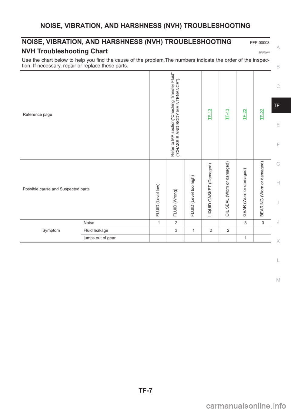
NOISE, VIBRATION, AND HARSHNESS (NVH) TROUBLESHOOTINGPFP:00003
NVH Troubleshooting ChartEDS000I4
Use the chart below to help you find the cause of the problem.The numbers indicate the order of the inspec-
tion. If necessary, repair or replace these parts.
Reference page
Refer to MA section("Checking Transfer Fluid"
("CHASSIS AND BODY MAINTENANCE").
TF-13
TF-13TF-22TF-22
Possible cause and Suspected parts
FLUID (Level low)
FLUID (Wrong)
FLUID (Level too high)
LIQUID GASKET (Damaged)
OIL SEAL (Worn or damaged)
GEAR (Worn or damaged)
BEARING (Worn or damaged)
SymptomNoise 1 2 3 3
Fluid leakage 3 1 2 2
jumps out of gear 1
Page 2635 of 3833

TRANSFER ASSEMBLY
TF-25
C
E
F
G
H
I
J
K
L
MA
B
TF
2. Using a drift, install the selected adjusting shim and gear ring
bearing outer race.
3. Install the oil defense, and tighten the mounting bolts to the
specified torque. The clearance between the oil defense and
transfer case (dimension A) should be the following.
CAUTION:
Do not reuse the mounting bolts.
4. Install the magnet.
5. Using a drift, drive the oil seal until it becomes flush with the
case end.
CAUTION:
●When checking the overall preload torque, measure it
without the oil seal, then install the oil seal.
●Discard old oil seals; replace with new ones.
●Apply onto oil seal lips, and gear oil onto the circumfer-
ence of the oil seal.
6. Apply recommended sealant to filler plug and its threads before
installing it to the transfer case.
7. Apply recommended sealant to breather tube and install it to the transfer case.
8. Install the drive gear assembly.
9. Install the adapter case.
10. Install the pinion sleeve assembly.
11. Check backlash, preload torque, tooth contact, and companion flange runout.
●TF-14, "Assembly Inspection"
CAUTION:
Measure the overall preload torque without the oil seal.
SDIA0538E
Tightening torque
: 6.9 - 8.8 N·m (0.7 - 0.9 kg-m, 61 - 78 in-lb)
Clearance between oil defense and transfer case
Dimension A : 1.0 - 3.5 mm (0.04 - 0.138 in)
Filler plug tightening torque : 9.8 - 19.6 N·m (1.0 - 1.9 kg-m, 87 - 173 in-lb)
Plug tightening torque : 15 - 19 N·m (1.5 - 2.0 kg-m, 11 - 14 ft-lb)
TFB0283D
SDIA0539E
Page 2636 of 3833
TF-26
TRANSFER ASSEMBLY
Drive gear assembly
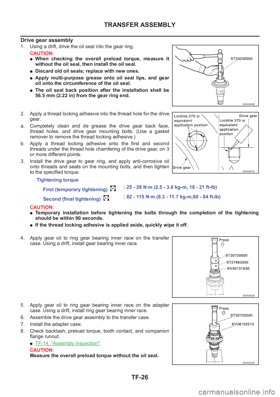
1. Using a drift, drive the oil seal into the gear ring.
CAUTION:
●When checking the overall preload torque, measure it
without the oil seal, then install the oil seal.
●Discard old oil seals; replace with new ones.
●Apply multi-purpose grease onto oil seal lips, and gear
oil onto the circumference of the oil seal.
●The oil seal back position after the installation shall be
56.5 mm (2.22 in) from the gear ring end.
2. Apply a thread locking adhesive into the thread hole for the drive
gear.
a. Completely clean and de grease the drive gear back face,
thread holes, and drive gear mounting bolts. (Use a gasket
remover to remove the thread locking adhesive.)
b. Apply a thread locking adhesive onto the first and second
threads under the thread hole chamfering of the drive gear, on 3
or more different points.
3. Install the drive gear to gear ring, and apply anti-corrosive oil
onto threads and seats on the mounting bolts, and then tighten
to the specified torque.
CAUTION:
●Temporary installation before tightening the bolts through the completion of the tightening
should be within 90 seconds.
●If the thread locking adhesive is applied aside, quickly wipe it off.
4. Apply gear oil to ring gear bearing inner race on the transfer
case. Using a drift, install gear bearing inner race.
5. Apply gear oil to ring gear bearing inner race on the adapter
case. Using a drift, install ring gear bearing inner race.
6. Assemble the drive gear assembly to the transfer case.
7. Install the adapter case.
8. Check backlash, preload torque, tooth contact, and companion
flange runout.
●TF-14, "Assembly Inspection".
CAUTION:
Measure the overall preload torque without the oil seal.
SDIA0540E
Tightening torque
First (temporary tightening) : 25 - 29 N·m (2.5 - 3.0 kg-m, 18 - 21 ft-lb)
Second (final tightening) : 82 - 115 N·m (8.3 - 11.7 kg-m,60 - 84 ft-lb)
SDIA0541E
SDIA0543E
SDIA0544E
Page 2637 of 3833

TRANSFER ASSEMBLY
TF-27
C
E
F
G
H
I
J
K
L
MA
B
TF
Adapter case
1. Select the adjusting shim on the gear ring bearing.
●TF-23, "SELECTIONG ADJUSTING SHIMS".
2. Install the oil gutter.
3. Using a drift, install the selected adjusting shim and gear ring
bearing outer race to the adapter case.
4. Using a drift, drive the oil seal until it becomes flush with the
case end.
CAUTION:
●When checking the overall preload torque, measure it
without the oil seal, then install the oil seal.
●Discard old oil seals; replace with new ones.
●Apply multi-purpose grease onto oil seal lips, and gear
oil onto the circumference of the oil seal.
5. Apply recommended sealant on drain plug and install it to the
adapter case.
6. Apply multi-purpose grease lightly and evenly onto an O-ring, and install it to the adapter case.
CAUTION:
Do not reuse the O-ring.
7. Install the adapter case to the transfer case, and apply anti-cor-
rosive oil onto threads and seats on the mounting bolts. Tighten
to the specified torque.
8. Check backlash, preload torque, tooth contact, and companion
flange runout.
●TF-14, "Assembly Inspection".
CAUTION:
Measure the overall preload torque without the oil seal.
Pinion sleeve assembly
1. Select the pinion sleeve shim.
●TF-23, "SELECTIONG ADJUSTING SHIMS".
SDIA0545E
Drain plug tightening torque
: 9.8 - 19.6 N·m (1.0 -1.9 kg-m, 87 - 173 in-lb)
Tightening torque
: 14 - 16 N·m (1.4 -1.7 kg-m, 11 - 12 ft-lb)
SDIA0546E
SDIA0547E
Page 2680 of 3833
RFD-4
PREPARATION
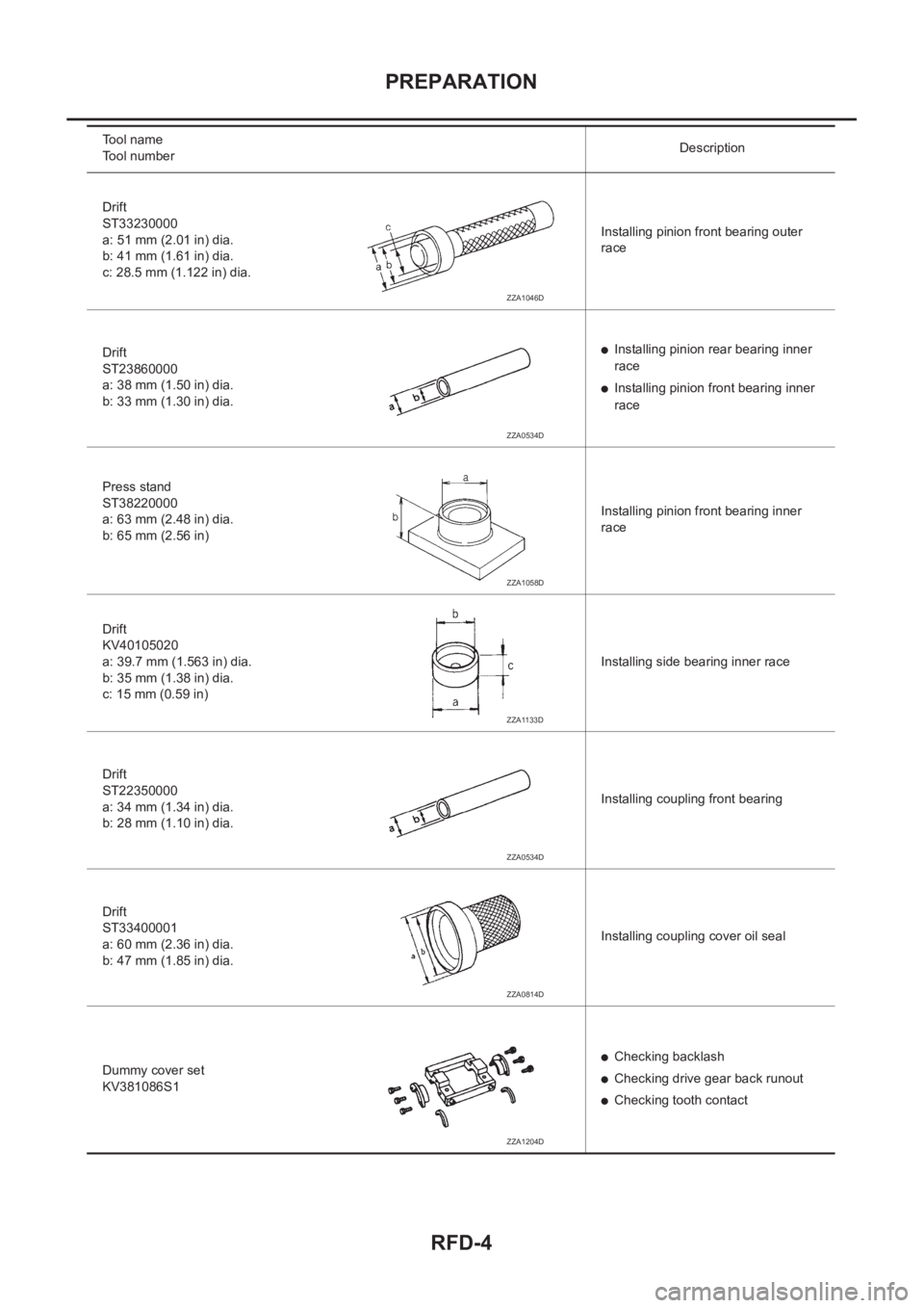
Drift
ST33230000
a: 51 mm (2.01 in) dia.
b: 41 mm (1.61 in) dia.
c: 28.5 mm (1.122 in) dia.Installing pinion front bearing outer
race
Drift
ST23860000
a: 38 mm (1.50 in) dia.
b: 33 mm (1.30 in) dia.
●Installing pinion rear bearing inner
race
●Installing pinion front bearing inner
race
Press stand
ST38220000
a: 63 mm (2.48 in) dia.
b: 65 mm (2.56 in)Installing pinion front bearing inner
race
Drift
KV40105020
a: 39.7 mm (1.563 in) dia.
b: 35 mm (1.38 in) dia.
c: 15 mm (0.59 in)Installing side bearing inner race
Drift
ST22350000
a: 34 mm (1.34 in) dia.
b: 28 mm (1.10 in) dia.Installing coupling front bearing
Drift
ST33400001
a: 60 mm (2.36 in) dia.
b: 47 mm (1.85 in) dia.Installing coupling cover oil seal
Dummy cover set
KV381086S1
●Checking backlash
●Checking drive gear back runout
●Checking tooth contact Tool name
Tool numberDescription
ZZA1046D
ZZA0534D
ZZA1058D
ZZA1133D
ZZA0534D
ZZA0814D
ZZA1204D
Page 2699 of 3833
REAR FINAL DRIVE ASSEMBLY
RFD-23
C
E
F
G
H
I
J
K
L
MA
B
RFD
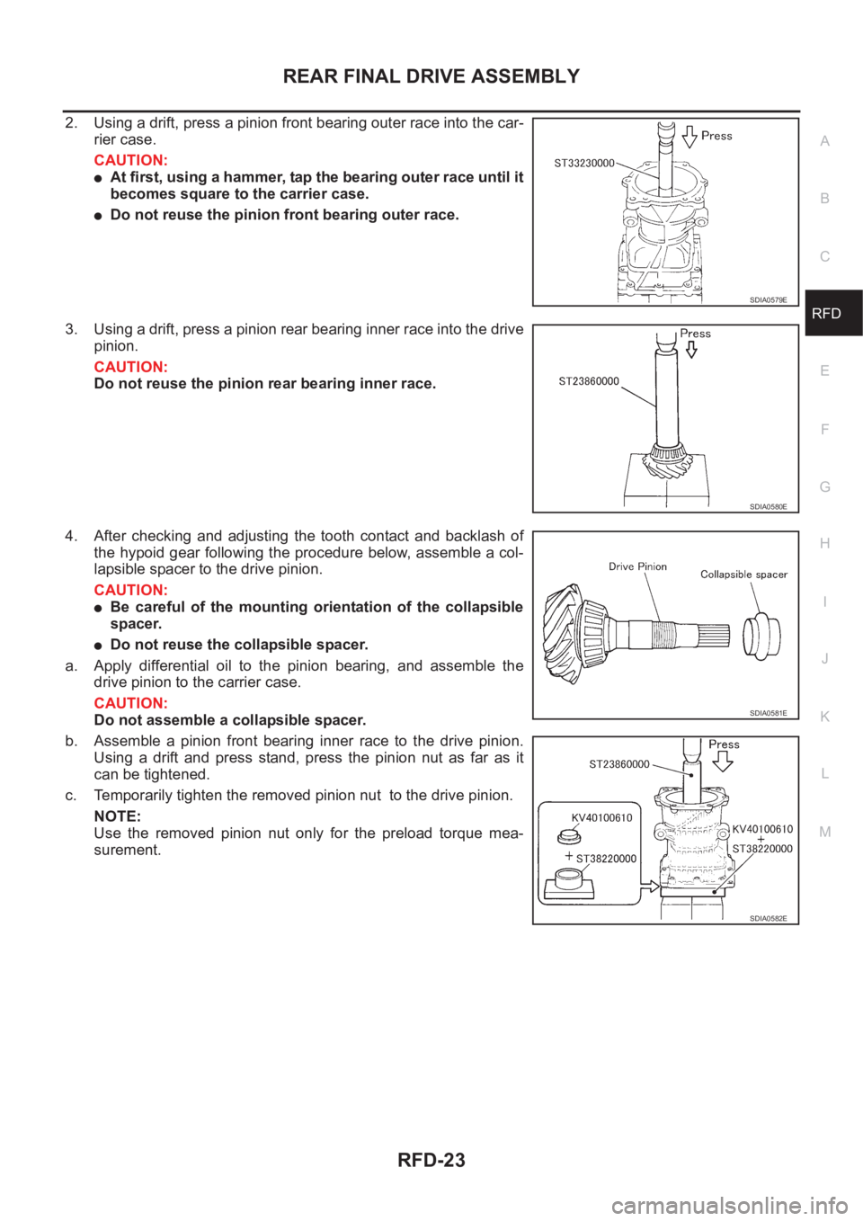
2. Using a drift, press a pinion front bearing outer race into the car-
rier case.
CAUTION:
●At first, using a hammer, tap the bearing outer race until it
becomes square to the carrier case.
●Do not reuse the pinion front bearing outer race.
3. Using a drift, press a pinion rear bearing inner race into the drive
pinion.
CAUTION:
Do not reuse the pinion rear bearing inner race.
4. After checking and adjusting the tooth contact and backlash of
the hypoid gear following the procedure below, assemble a col-
lapsible spacer to the drive pinion.
CAUTION:
●Be careful of the mounting orientation of the collapsible
spacer.
●Do not reuse the collapsible spacer.
a. Apply differential oil to the pinion bearing, and assemble the
drive pinion to the carrier case.
CAUTION:
Do not assemble a collapsible spacer.
b. Assemble a pinion front bearing inner race to the drive pinion.
Using a drift and press stand, press the pinion nut as far as it
can be tightened.
c. Temporarily tighten the removed pinion nut to the drive pinion.
NOTE:
Use the removed pinion nut only for the preload torque mea-
surement.
SDIA0579E
SDIA0580E
SDIA0581E
SDIA0582E
Page 2749 of 3833

BRAKE FLUID
BR-9
C
D
E
G
H
I
J
K
L
MA
B
BR
BRAKE FLUIDPFP:KN100
Checking Brake Fluid Level EFS000C5
●Confirm reservoir tank fluid level is within specifications
(between MAX and MIN lines).
●Visually check around reservoir tank for fluid leaks.
●If fluid level is excessively low, check brake system for leaks.
●If warning lamp remains illuminated after parking lever is
released, check brake system for fluid leakage.
Checking Brake LineEFS001C5
CAUTION:
If leakage occurs around joints, retighten or, if necessary, replace damaged parts.
1. Check brake line (tube and hoses) for cracks, deterioration or
other damage. Replace and damaged parts.
2. Check for oil leakage by fully depressing brake pedal while
engine is running.
Changing Brake FluidEFS000C3
CAUTION:
●Refill with new brake fluid “DOT 3 or DOT 4”.
●Always keep fluid level higher than minimum line on reservoir tank.
●Never reuse drained brake fluid.
●Be careful not to splash brake fluid on spill or splash on painted areas; it may cause paint damage.
If brake fluid is splashed on painted areas, wash it away water immediately.
1. Connect a vinyl tube to the air bleeder.
2. Drain brake fluid gradually from the air bleeder of each wheel
while depressing the brake pedal.
3. Turn OFF ignition switch. Remove ABS actuator connector.
SFIA0066J
SBR389C
BRA0007D
Page 2788 of 3833

BRC-4
[4WD/ABS]
PRECAUTIONS
[4WD/ABS]PRECAUTIONSPFP:00001
Precautions for brake systemEFS001B6
●Recommended fluid is brake fluid “DOT 3 ”or “DOT 4”.
●Never reuse drained brake fluid.
●Be careful not to splash brake fluid on painted areas.
●To clean or wash all parts of master cylinder, disc brake caliper and wheel cylinder, use clean brake fluid.
●Never use mineral oils such as gasoline or kerosene. They will ruin rubber parts of the hydraulic system.
●Use flare nut wrench when removing and installing brake tube.
●Always torque brake lines when installing.
●Burnish the brake contact surfaces after refinishing or replacing
drums or rotors, after replacing pads or linings, or if a soft pedal
occurs at very low mileage. Refer to BR-10, "
Brake Burnishing
Procedure" .
●Before working, turn OFF ignition switch. Disconnect connectors
for ABS actuator and control module or battery terminals.
WARNING:
●Clean brake pads and shoes with a waste cloth, then wipe
with a dust collector.
Precautions for brake controlEFS001B7
●If malfunction is indicated by 4WD warning lamp and/or ABS warning lamp, collect necessary information
from customer (what symptoms are present under what conditions). Find out possible causes before start-
ing service. Besides electrical system inspection, check operation of ABS actuator.
●If malfunction is detected, proceed to trouble diagnosis after checking tire pressure and tire wear.
●Stopping distance or steering stability may be deteriorated by the following conditions. Tire size and type
are in improper combination. Brake pads are not Nissan genuine parts.
●Fitting tires of different size on vehicle can be cause of longitudinal vibration. Always use tires of the same
size and brand. Exchange front and rear tires on the following conditions: Longitudinal vibration occurs in
vehicle with tires of the same size and brand. After replacement, perform trouble diagnosis. 1580|None
●4WD/ABS function may have a failure or error under following condition: There is radio, antenna, or
antenna lead-in wire (including wiring) near control module.
●If aftermarket parts (e.g. Car stereo equipment, CD player) have been installed, check electrical har-
nesses for pinches, open, and improper wiring.
SBR820BA
Page 2911 of 3833

PS-1
POWER STEERING SYSTEM
G STEERING
CONTENTS
C
D
E
F
H
I
J
K
L
M
SECTION
A
B
PS
POWER STEERING SYSTEM
PRECAUTIONS .......................................................... 2
Precautions for Supplemental Restraint System
(SRS) “AIR BAG” and “SEAT BELT PRE-TEN-
SIONER” .................................................................. 2
Caution ..................................................................... 2
PREPARATION ........................................................... 3
Special Service Tools ............................................... 3
NOISE, VIBRATION, AND HARSHNESS (NVH)
TROUBLESHOOTING ................................................ 4
NVH Trouble shooting Chart .................................... 4
POWER STEERING FLUID ........................................ 5
Checking Fluid Level ........................................... ..... 5
Checking Fluid Leak ............................................ ..... 5
Bleeding Hydraulic System ...................................... 5
STEERING WHEEL .................................................... 6
On-Vehicle Inspection and Service .......................... 6
PLAY INSPECTION .............................................. 6
NEUTRAL POSITION INSPECTION .................... 6
STEERING TORQUE CHECK .............................. 6
STEERING ANGLE INSPECTION ........................ 6
Removal and Installation .......................................... 7
REMOVAL ............................................................. 7
INSTALLATION ..................................................... 7
STEERING COLUMN ................................................. 9
Removal and Installation .......................................... 9
REMOVAL OF LOWER JOINT AND HOLE
COVER ................................................................. 9
INSTALLATION OF LOWER JOINT AND HOLE
COVER ................................................................. 9
REMOVAL OF STEERING COLUMN ASSEM-
BLY ...................................................................... 10
INSTALLING STEERING COLUMN ASSEMBLY ... 10
Disassembly and Assembly .................................... 11
DISASSEMBLY .................................................... 11
INSPECTION AFTER DISASSEMBLY. ............... 11
ASSEMBLY .......................................................... 11
POWER STEERING GEAR AND LINKAGE ............ 12
Removal and Installation ........................................ 12
REMOVAL ........................................................... 12INSTALLATION ................................................... 12
Components ........................................................... 14
MODEL PR24AD ................................................. 14
Disassembly and Assembly .................................... 15
DISASSEMBLY ................................................... 15
INSPECTION AFTER DISASSEMBLY ................ 16
ASSEMBLY ......................................................... 17
POWER STEERING OIL PUMP ............................... 24
On-Vehicle Inspection and Service ......................... 24
OIL PUMP PULLEY HYDRAULIC PRESSURE
INSPECTION ...................................................... 24
Removal and Installation (QR20DE and QR25DE
engine models) ....................................................... 24
REMOVAL ........................................................... 24
INSTALLATION ................................................... 24
Disassembly and Assembly(QR20DE and
QR25DE engine models) ........................................ 25
INSPECTION BEFORE DISASSEMBLY ............. 25
DISASSEMBLY ................................................... 25
INSPECTION AFTER DISASSEMBLY ................ 26
ASSEMBLY ......................................................... 26
Removal and Installation (YD22DDTi engine
model) ..................................................................... 29
Disassembly and Assembly (YD22DDTi engine
model) ..................................................................... 30
INSPECTION BEFORE DISASSEMBLY ............. 30
DISASSEMBLY ................................................... 31
INSPECTION AFTER DISASSEMBLY ................ 32
ASSEMBLY ......................................................... 32
HYDRAULIC LINE .................................................
... 34
Removal and Installation ........................................ 34
SERVICE DATA AND SPECIFICATIONS (SDS) ...... 36
Wheel ..................................................................... 36
Steering Angle ........................................................ 36
Steering Column ..................................................... 36
Steering Linkage ..................................................... 36
Steering Gear ......................................................... 37
Oil Pump ................................................................. 37
Steering Fluid .......................................................... 37