checking oil NISSAN X-TRAIL 2001 Service User Guide
[x] Cancel search | Manufacturer: NISSAN, Model Year: 2001, Model line: X-TRAIL, Model: NISSAN X-TRAIL 2001Pages: 3833, PDF Size: 39.49 MB
Page 168 of 3833

EM-118
[YD22DDTi]
DRIVE BELTS
DRIVE BELTS
PFP:02117
Checking Drive BeltsEBS00LRA
●Before inspecting the engine, make sure the engine has cooled
down; wait approximately 30 minutes after the engine has been
stopped.
●Visually inspect all belts for wear, damage or cracks on contact-
ing surfaces and edge areas.
●When measuring deflection, apply 98 N (10 kg, 22 lb) at the
marked point ( ).
CAUTION:
●When checking belt deflection immediately after installa-
tion, first adjust it to the specified value. Then, after turn-
ing the crankshaft two turns or more, re-adjust to the
specified value to avoid variation in deflection between
pulleys.
●Tighten idler pulley lock nut by hand and measure deflection without looseness.
Belt Deflection:
*: When engine is cold.
Tension AdjustmentEBS00LRB
●Adjust belts with the parts shown below.
CAUTION:
●When a new belt is installed as a replacement, adjust it to the value specified under “New” value
because of insufficient adaptability with pulley grooves.
●If the belt deflection of the current belt is out of the “Limit for re-adjusting”, adjust to the
“Adjusted” value.
●When checking belt deflection immediately after installation, first adjust it to the specified value.
Then, after turning crankshaft two turns or more, re-adjust it to the specified value to avoid vari-
ation in deflection between pulleys.
●Make sure the belts are fully fitted into the pulley grooves during installation.
●Handle with care to avoid smearing the belts with engine oil or cooling water etc.
●Do not twist or bend the belts with strong force.
JEM249G
Applied beltBelt deflection with 98 N (10 kg, 22 lb) force applied* mm (in)
New Adjusted Limit for re-adjusting
Air conditioner compressor belt 4 - 5 (0.16 - 0.20) 6 - 7 (0.24 - 0.28) 8.5 (0.335)
Alternator and water pump belt 9.0 - 10.5 (0.354 - 0.413) 11.0 - 12.5 (0.433 - 0.492) 16.5 (0.650)
Applied belt Belt adjustment method
Air conditioner compressor belt Adjusting bolt on idler pulley
Alternator and water pump belt Adjusting bolt on alternator
Page 182 of 3833

EM-132
[YD22DDTi]
EXHAUST MANIFOLD AND TURBOCHARGER
TROUBLE DIAGNOSIS OF TURBOCHARGER
Preliminary check:
●Check that the engine oil level is between MIN and MAX of the dipstick. (When the engine oil amount is
more than MAX, the engine oil flows into the inlet duct through the blow-by gas passage, and the turbo-
charger is misjudged failure.)
●Ask the customer if he/she always runs the vehicle in idle engine speed to cool the engine oil down after
driving.
●Replace the turbocharger assembly when any malfunction is found after unit inspections specified in the
table below.
●If no malfunction is found after the unit inspections, judge that the turbocharger body has no failure. Check
the other parts again.
A: Large possibility
B: Medium possibility
C: Small possibilityInspection item Inspection resultSymptom
(when each inspection item meets each inspection result)
Engine oil
leakageSmoke NoiseInsufficient power/
acceleration failure
Turbine wheelEngine oil leaks C A C C
Carbon is accumulated C A B B
Friction with housing C B A B
Blades are bent or broken — — A A
Compressor wheelInside the air inlet is seriously con-
taminated by engine oil.BB— —
Friction with housing C B A B
Blades are bent or broken — — A A
After checking both turbine and
compressor, inspect rotor shaft
end play.There is resistance when the rotor
shaft is rotated by your fingertips.—CC B
The rotor shaft sometimes does not
rotate by your fingertips.——— A
There is too much play in the bear-
ing.CCB C
Oil return portCarbon or sludge is accumulated in
the waste oil hole.CAC C
Page 232 of 3833

EM-182
[YD22DDTi]
CYLINDER HEAD
CYLINDER HEAD
PFP:11041
On-Vehicle ServiceEBS00LRV
CHECKING COMPRESSION PRESSURE
1. Warm up engine thoroughly. Then, stop it.
2. Using CONSULT-II, make sure no error codes are indicated for self-diagnosis items. Refer to EC-1412,
"Basic Inspection" .
●Do not disconnect CONSULT-II until the end of this operation; it will be used to check engine rpm and
for error detection at the end of this operation.
3. Disconnect the negative battery terminal.
4. Remove charge air cooler. Refer to EM-122, "
Removal and Installation"
5. To prevent fuel from being injected during inspection, remove
fuel supply pump fuse [ENG CONT (20A)] from fuse box on the
left side of engine compartment.
●Among marks on fuse box, [ENG CONT 2 (20A)] is for fuel
supply pump fuse.
6. Remove glow plugs from all the cylinders. Refer to EM-138,
"Removal and Installation" .
CAUTION:
●Before removal, clean the surrounding area to prevent
entry of any foreign materials into the engine.
●Carefully remove glow plugs to prevent any damage or
breakage.
●Handle with care to avoid applying any shock to glow plugs.
7. Install adapter to installation holes of glow plugs and connect
compression gauge for diesel engine.
8. Connect battery negative terminal.
9. Set the ignition switch to “START” and crank. When gauge
pointer stabilizes, read compression pressure and engine rpm.
Repeat the above steps for each cylinder.
●Always use a fully-charged battery to obtain specified engine
speed.
Compression pressure
Unit: kPa (bar, kg/cm2 , psi)/rpm
●When engine rpm is out of the specified range, check the specific gravity of battery liquid. Measure
again under corrected conditions.
●If engine rpm exceeds the limit, check valve clearance and combustion chamber components (valves,
valve seats, cylinder head gaskets, piston rings, pistons, cylinder bores, cylinder block upper and lower
surfaces) and measure again.
●If compression pressure is low in some cylinders, apply engine oil from glow plug installation hole. Then
check pressure again.
–If compression pressure becomes normal after applying engine oil, piston ring may be worn or dam-
aged. Check piston ring for malfunction. If any, replace piston ring.
–If compression pressure is still low after applying engine oil, valve may be malfunctioning. Check valve
for malfunction. If contact malfunction is found, replace valve or valve seat.
●If compression pressure in adjacent two cylinders is low after applying engine oil, pressure may be
leaking from gasket. In this case, replace cylinder head gasket.
10. Complete this operation as follows:
PBIC0680E
: 18 - 21 N·m (1.8 - 2.2 kg-m, 13 - 15 ft-lb)
SEM112G
Standard Minimum Difference limit between cylinders
2,893 (28.9, 29.5, 419)/200 2,452 (24.52, 25.0, 356)/200 490 (4.90, 5.0, 71)/200
Page 287 of 3833

ENGINE OIL
LU-7
[QR]
C
D
E
F
G
H
I
J
K
L
MA
LU
ENGINE OILPFP:KLA92
InspectionEBS00KO3
ENGINE OIL LEVEL
●Before starting the engine, put vehicle horizontally then check
the engine oil level. If the engine is already started, stop it and
allow 10 minutes before checking.
●Check that the engine oil level is within the range shown in the
figure.
●If it is out of range, adjust it.
ENGINE OIL APPEARANCE
●Check the engine oil for white turbidity or remarkable contamination.
●If the engine oil becomes turbid and white, it is highly probable that it is contaminated with engine coolant.
Find the cause and repair.
ENGINE OIL LEAKAGE
Check for engine oil leakage around the following area.
●Oil pan
●Oil pan drain plug
●Oil pressure switch
●Oil filter
●Oil cooler
●Intake valve timing control cover and intake valve timing control solenoid valve
●Front cover
●Mating surface between cylinder block and cylinder head
●Mating surface between cylinder head and rocker cover
●Crankshaft oil seal.
OIL PRESSURE CHECK
WARNING:
●Be careful not to burn yourself, as the engine oil is hot.
●Engine oil pressure check should be done in “ Parking
position” (A/T model) or “Neutral position” (M/T model).
1. Check engine oil level. Refer to LU-7, "
ENGINE OIL LEVEL" .
2. Remove the undercover.
3. Remove the oil pressure switch to connect the oil pressure
gauge.
4. After warming up the engine, check that oil pressure corre-
sponding to the engine speed is produced.
Engine oil pressure [Engine oil temperature at 80 °C (176 °F)]
5. After checking, install the oil pressure switch as follows.
a. Remove old sealant adhering to the switch and engine.
b. Apply thread sealant.
Use Genuine Liquid Gasket or equivalent.
PBIC0249E
KBIA0275E
Engine speed (rpm) Idle speed 2,000 6,000
Engine pressure
kPa (bar, kg/cm
2 , psi)Approx. 98 (0.98, 1.0, 14) or more Approx. 294 (2.9, 3.0, 43) or more Approx. 392 (3.9, 4.0, 57) or more
Page 298 of 3833

LU-18
[YD22DDTi]
ENGINE OIL
ENGINE OIL
PFP:KLA92
InspectionEBS00B03
ENGINE OIL LEVEL AND MUDDINESS
●Before starting the engine, put vehicle horizontally then check
the engine oil level. If the engine is already started, stop it and
allow 10 minutes before checking.
●Check that the engine oil level is within the range shown in the
figure.
●If it is out of range, adjust it.
●Check the engine oil for white turbidity or remarkable contamina-
tion.
●If the engine oil becomes turbid and white, it is highly probable
that it is contaminated with engine coolant. Find the cause and
repair.
ENGINE OIL LEAKAGE
Check for engine oil leakage around the following area.
●Oil pan
●Oil pan drain plug
●Oil pressure switch
●Oil filter bracket
●Oil cooler.
●Oil pump housing
●Vacuum pump
●Cylinder head rear cover assembly
●Chain case
●Mating surface between cylinder block and cylinder head
●Mating surface between cylinder head and rocker cover
●Crankshaft oil seal. Refer to LU-18, "ENGINE OIL LEVEL AND MUDDINESS" .
ENGINE OIL PRESSURE CHECK
WARNING:
●Be careful not to burn yourself, as the engine oil is hot.
●Oil pressure check should be done in “ Neutral position”.
1. Check the engine oil level. Refer to LU-18, "
ENGINE OIL LEVEL
AND MUDDINESS" .
2. Remove the undercover.
3. Remove the oil pressure switch to connect the oil pressure
gauge.
4. After warming up the engine, check that oil pressure corre-
sponding to the engine speed is produced.
Engine oil pressure [Engine oil temperature at 80 °C (176 °F)]
5. After checking, install the oil pressure switch as follows.
a. Remove old sealant adhering to the switch and engine.
b. Apply thread sealant.
Use Genuine Liquid Gasket or equivalent.
SBIA0122E
SBIA0123E
Engine speed (rpm) Idle speed 2,000 4,000
Engine pressure
kPa (bar, kg/cm
2 , psi)Approx. 140 (1.40, 1.43, 20.3) or
moreApprox. 270 (2.69, 2.75, 39.1) or
moreApprox. 430 (4.29, 4.38, 62.3) or
more
Page 317 of 3833

RADIATOR
CO-11
[QR]
C
D
E
F
G
H
I
J
K
L
MA
CO
RADIATORPFP:21400
Removal and InstallationEBS00KOI
WARNING:
Never remove the radiator cap when the engine is hot. Serious burns could occur from high pressure
engine coolant escaping from the radiator. Wrap a thick cloth around the cap. Slowly turn it a quarter
turn to allow built-up pressure to escape. Carefully remove the cap by turning it all the way.
REMOVAL
1. Drain engine coolant. Refer to CO-9, "DRAINING ENGINE COOLANT" .
2. Remove air duct with air cleaner assembly.
3. Remove A/T oil cooler hose.
●Install blind plug to avoid leakage of A/T fluid.
4. Disconnect radiator upper hose, lower hose and mounting bracket.
5. Remove radiator and radiator fan assembly
CAUTION:
Do not damage or scratch radiator core when removing.
INSTALLATION
●Reinstall any parts removed in reverse order of removal.
●Check for engine coolant leaks. Refer to CO-9, "CHECKING RADIATOR SYSTEM FOR LEAKS" .
PBIC0237E
1. Radiator 2. Bracket 3. Mounting rubber
4. A/T oil cooler hose 5. Radiator hose (lower) 6. Radiator fan assembly
7. Reservoir tank 8. Radiator hose (upper) 9. Radiator cap
Page 570 of 3833

EC-220
[QR25(WITH EURO-OBD)]
DTC P0300 - P0304 MULTIPLE CYLINDER MISFIRE, NO. 1 - 4 CYLINDER MIS-
FIRE
5. CHECK IGNITION SPARK
1. Disconnect ignition coil assembly from rocker cover.
2. Connect a known-good spark plug to the ignition coil assembly.
3. Place end of spark plug against a suitable ground and crank engine.
4. Check for spark.
OK or NG
OK >> GO TO 6.
NG >> Check ignition coil, power transistor and their circuits.
Refer to EC-379, "
IGNITION SIGNAL" .
6. CHECK SPARK PLUGS
Remove the spark plugs and check for fouling, etc.
OK or NG
OK >> GO TO 7.
NG >> Repair or replace spark plug(s) with standard type
one(s). For spark plug type, refer to MA-24, "
Checking
and Changing Spark Plugs" .
7. CHECK COMPRESSION PRESSURE
Check compression pressure. Refer to EM-59, "
CHECKING COMPRESSION PRESSURE" .
OK or NG
OK >> GO TO 8.
NG >> Check pistons, piston rings, valves, valve seats and cylinder head gaskets.
8. CHECK FUEL PRESSURE
1. Install all removed parts.
2. Release fuel pressure to zero. Refer to EC-42, "
FUEL PRESSURE RELEASE" .
3. Install fuel pressure gauge and check fuel pressure. Refer to EC-42, "
FUEL PRESSURE CHECK" .
OK or NG
OK >> GO TO 9.
NG >> Follow the Instruction of “FUEL PRESSURE CHECK”.
SEF575Q
SEF156I
Standard:
1,190 kPa (11.9 bar, 12.1 kg/cm2 , 172 psi)/250
rpm
Minimum:
990 kPa (9.9 bar, 10.1 kg/cm
2 , 144 psi)/250 rpm
Difference between each
cylinder:98 kPa (0.98 bar, 1.0 kg/cm
2 , 14 psi)/250 rpm
At idle: Approx. 350 kPa (3.5 bar, 3.57 kg/cm
2 , 51 psi)
Page 1299 of 3833

DTC P0300 - P0304 MULTIPLE CYLINDER MISFIRE, NO. 1 - 4 CYLINDER MIS-
FIRE
EC-949
[QR20(WITH EURO-OBD)]
C
D
E
F
G
H
I
J
K
L
MA
EC
5.CHECK IGNITION SPARK
1. Disconnect ignition coil assembly from rocker cover.
2. Connect a known-good spark plug to the ignition coil assembly.
3. Place end of spark plug against a suitable ground and crank engine.
4. Check for spark.
OK or NG
OK >> GO TO 6.
NG >> Check ignition coil, power transistor and their circuits.
Refer to EC-1074, "
IGNITION SIGNAL" .
6.CHECK SPARK PLUGS
Remove the spark plugs and check for fouling, etc.
OK or NG
OK >> GO TO 7.
NG >> Repair or replace spark plug(s) with standard type
one(s). For spark plug type, refer to MA-24, "
Checking
and Changing Spark Plugs" .
7.CHECK COMPRESSION PRESSURE
Check compression pressure. Refer to EM-59, "
CHECKING COMPRESSION PRESSURE" .
OK or NG
OK >> GO TO 8.
NG >> Check pistons, piston rings, valves, valve seats and cylinder head gaskets.
8.CHECK FUEL PRESSURE
1. Install all removed parts.
2. Release fuel pressure to zero. Refer to EC-775, "
FUEL PRESSURE RELEASE" .
3. Install fuel pressure gauge and check fuel pressure. Refer to EC-775, "
FUEL PRESSURE CHECK" .
OK or NG
OK >> GO TO 9.
NG >> Follow the Instruction of “FUEL PRESSURE CHECK”.
SEF575Q
SEF156I
Standard:
1,190 kPa (11.9 bar, 12.1 kg/cm2 , 172 psi)/250
rpm
Minimum:
990 kPa (9.9 bar, 10.1 kg/cm
2 , 144 psi)/250 rpm
Difference between each
cylinder:98 kPa (0.98 bar, 1.0 kg/cm
2 , 14 psi)/250 rpm
At idle: Approx. 350 kPa (3.5 bar, 3.57 kg/cm
2 , 51 psi)
Page 1859 of 3833

DTC P1217 OVERHEAT (COOLING SYSTEM)
EC-1509
[YD]
C
D
E
F
G
H
I
J
K
L
MA
EC
When the engine coolant temperature reaches an abnormally high temperature condition, a malfunction is
indicated.
CAUTION:
When a malfunction is indicated, be sure to replace the coolant following the procedure in the MA-27,
"Changing Engine Coolant" . Also, replace the engine oil.
1. Fill radiator with coolant up to specified level with a filling speed of 2 liters per minute. Be sure to
use coolant with the proper mixture ratio. Refer to MA-18, "
Engine Coolant Mixture Ratio" .
2. After refilling coolant, run engine to ensure that no water-flow noise is emitted.
Overall Function CheckEBS004QV
Use this procedure to check the overall function of the cooling fan. During this check, a DTC might not be con-
firmed.
WARNING:
Never remove the radiator cap when the engine is hot. Serious burns could be caused by high pres-
sure fluid escaping from the radiator.
Wrap a thick cloth around the cap. Carefully remove the cap by turning it a quarter turn to allow built-
up pressure to escape. Then turn the cap all the way off.
WITH CONSULT-II
1. Check the coolant level in the reservoir tank and radiator.
Allow engine to cool before checking coolant level.
If the coolant level in the reservoir tank and/or radiator is below
the proper range, skip the following steps and go to EC-1511,
"Diagnostic Procedure" .
2. Confirm whether customer filled the coolant or not. If customer
filled the coolant, skip the following steps and go to EC-1511,
"Diagnostic Procedure" .
3. Turn ignition switch “ON”.
4. Perform “COOLING FAN” in “ACTIVE TEST” mode with CON-
SULT-II and make sure that cooling fans operate when touching
“HIGH” or “LOW”.
If NG, go to EC-1511, "
Diagnostic Procedure" .
DTC Malfunction is detected when ... Check Items (Possible Cause)
P1217
●Cooling fan does not operate properly (Overheat).
●Cooling fan system does not operate properly
(Overheat).
●Engine coolant was not added to the system using
the proper filling method.
●Harness or connectors
(The cooling fan circuit is open or shorted.)
●Cooling fan
●Radiator hose
●Radiator
●Radiator cap
●Water pump
●Thermostat
●Engine coolant temperature sensor
For more information, refer to EC-1517, "
Main 12
Causes of Overheating" .
AEC640
SEF111X
Page 1977 of 3833
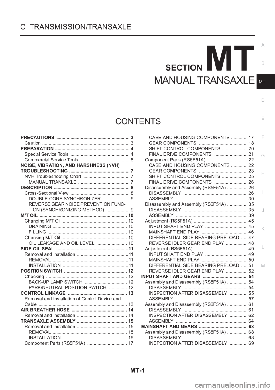
MT-1
MANUAL TRANSAXLE
C TRANSMISSION/TRANSAXLE
CONTENTS
D
E
F
G
H
I
J
K
L
M
SECTION
A
B
MT
MANUAL TRANSAXLE
PRECAUTIONS .......................................................... 3
Caution ..................................................................... 3
PREPARATION ........................................................... 4
Special Service Tools ............................................... 4
Commercial Service Tools ........................................ 6
NOISE, VIBRATION, AND HARSHNESS (NVH)
TROUBLESHOOTING ................................................ 7
NVH Troubleshooting Chart ..................................... 7
MANUAL TRANSAXLE ......................................... 7
DESCRIPTION ............................................................ 8
Cross-Sectional View ............................................... 8
DOUBLE-CONE SYNCHRONIZER ...................... 9
REVERSE GEAR NOISE PREVENTION FUNC-
TION (SYNCHRONIZING METHOD) ................... 9
M/T OIL ..................................................................... 10
Changing M/T Oil ................................................... 10
DRAINING ........................................................... 10
FILLING ............................................................... 10
Checking M/T Oil .................................................... 10
OIL LEAKAGE AND OIL LEVEL ......................... 10
SIDE OIL SEAL .........................................................11
Removal and Installation ......................................... 11
REMOVAL ............................................................ 11
INSTALLATION .................................................... 11
POSITION SWITCH .................................................. 12
Checking ................................................................ 12
BACK-UP LAMP SWITCH .................................. 12
PARK/NEUTRAL POSITION SWITCH ............... 12
CONTROL LINKAGE ............................................... 13
Removal and Installation of Control Device and
Cable ...................................................................... 13
AIR BREATHER HOSE ............................................ 14
Removal and Installation ........................................ 14
TRANSAXLE ASSEMBLY ........................................ 15
Removal and Installation ........................................ 15
REMOVAL ........................................................... 15
INSTALLATION ................................................... 16
Component Parts (RS5F51A) ................................ 17CASE AND HOUSING COMPONENTS .............. 17
GEAR COMPONENTS ....................................... 18
SHIFT CONTROL COMPONENTS ..................... 20
FINAL DRIVE COMPONENTS ........................... 21
Component Parts (RS6F51A) ................................. 22
CASE AND HOUSING COMPONENTS .............. 22
GEAR COMPONENTS ....................................... 23
SHIFT CONTROL COMPONENTS ..................... 25
FINAL DRIVE COMPONENTS ........................... 26
Disassembly and Assembly (RS5F51A) ................. 26
DISASSEMBLY ................................................... 26
ASSEMBLY ......................................................... 30
Disassembly and Assembly (RS6F51A) ................. 35
DISASSEMBLY ................................................... 35
ASSEMBLY ......................................................... 39
Adjustment (RS5F51A) ........................................... 45
INPUT SHAFT END PLAY .................................. 45
MAINSHAFT END PLAY ..................................... 46
DIFFERENTIAL SIDE BEARING PRELOAD ...... 47
REVERSE IDLER GEAR END PLAY .................. 48
Adjustment (RS6F51A) ........................................... 49
INPUT SHAFT END PLAY .................................. 49
MAINSHAFT END PLAY ..................................... 50
DIFFERENTIAL SIDE BEARING PRELOAD ...... 51
REVERSE IDLER GEAR END PLAY .................. 52
INPUT SHAFT AND GEARS .................................... 54
Assembly and Disassembly (RS5F51A) ................. 54
DISASSEMBLY ................................................... 54
INSPECTION AFTER DISASSEMBLY ................ 55
ASSEMBLY ......................................................... 57
Assembly and Disassembly (RS6F51A) ................. 61
DISASSEMBLY ................................................... 61
INSPECTION AFTER DISASSEMBLY ................ 62
ASSEMBLY ......................................................... 64
MAINSHAFT AND GEARS ....................................... 68
Assembly and Disassembly (RS5F51A) ................. 68
DISASSEMBLY ................................................... 68
INSPECTION AFTER DISASSEMBLY ................ 69