checking oil NISSAN X-TRAIL 2001 Service Owner's Guide
[x] Cancel search | Manufacturer: NISSAN, Model Year: 2001, Model line: X-TRAIL, Model: NISSAN X-TRAIL 2001Pages: 3833, PDF Size: 39.49 MB
Page 2915 of 3833

POWER STEERING FLUID
PS-5
C
D
E
F
H
I
J
K
L
MA
B
PS
POWER STEERING FLUIDPFP:KLF20
Checking Fluid LevelEGS0004B
●Check the fluid level with the engine OFF.
●Check that fluid level is between MAX and MIN marks on tank.
Fluid level should not exceed MAX mark. Excessive fluid will
cause fluid to leak from cap.
●Note that fluid level can change depending on temperature of
fluid. HIGH and LOW marks are shown on tank to indicate the
proper level at high temperature and low temperature respec-
tively.
CAUTION:
●Never reuse drained power steering fluid.
●Use DEXRONTM III or equivalent. Never use Nissan Power Steering Fluid Special, Nissan Matic
Fluid C, or D.
Checking Fluid LeakEGS0004C
Check hydraulic connections for any leak, crack, damage, loose-
ness, or wear.
1. Run engine until fluid temperature reaches 50 to 80°C (122 to
176°F) in reservoir tank. Keep engine speed at idle.
2. Turn steering wheel several times from stop to stop.
3. Turn the steering wheel clockwise or counter clockwise until it
reaches the stop and hold it for five seconds. Check for fluid
leak.
CAUTION:
Do not hold steering wheel at stop for 15 seconds or longer.
Otherwise, pump may be damaged.
4. If any leak is found on joint, loosen and retighten flair nut. Excessive tightening may damage O-ring,
washer, or connector.
Bleeding Hydraulic SystemEGS0004D
1. Lift vehicle.
2. Fill tank up to MAX mark. Turn steering wheel several times from stop to stop. Add fluid if fluid level goes
down. Repeat this step until there is no fluid decrease and no bubble in tank.
3. Start engine and repeat step above with engine at idle. Continue step until no decrease in fluid happens.
If bleeding is not complete, following symptoms can be observed.
●Bubbles are created in reservoir tank.
●Rattling noise can be heard from oil pump.
●Whining noise can be heard from oil pump.
Turn steering wheel slowly or stop vehicle. Sound of fluid movement may be heard from gear valve and
pump. This sound has nothing to do with steering performance or durability. HOT : Oil temperature 50 to 80°C (122 to 176°F)
COLD : Oil temperature 0 to 30°C (32 to 86°F)
STC0996D
SST836C
Page 3292 of 3833

ATC-16
PREPARATION
Recovery/Recycling
Recharging equipment (ACR4)Function: Refrigerant Recovery and
Recycling and Recharging
Electrical leak detectorPower supply:
●DC 12V (Cigarette lighter)
(J-43926)
Refrigerant dye leak detection kit
Kit includes:
(J-42220)
UV lamp and UV safety goggles
(J-41459)
HFC-134a (R-134a) Dye injector
Use with J-41447, 1/4 ounce
bottle
(J-41447)
HFC-134a (R-134a) Fluorescent
leak detection dye
(Box of 24, 1/4 ounce bottles)
(J-43872)
Refrigerant dye cleanerPower supply:
DC 12V (Battery terminal)
(J-42220)
UV lamp and UV safety gogglesPower supply: DC 12V (Battery
terminal)
For checking refrigerant leak when
fluorescent dye is installed in A/C
system.
Includes: UV lamp and UV safety
goggles
(J-41447)
HFC-134a (R-134a) Fluorescent
leak detection dye
(Box of 24, 1/4 ounce bottles)Application: For HFC-134a (R-134a)
PAG oil
Container: 1/4 ounce (7.4cc) bottle
(Includes self-adhesive dye
identification labels for affixing to
vehicle after charging system with
dye.) Tool number
Tool nameDescription
RJIA0195E
SHA705EB
ZHA200H
SHA438F
SHA439F
Page 3422 of 3833

ATC-146
REFRIGERANT LINES
Removal and Installation for Expansion Valve
EJS0028B
1. Use the refrigerant collecting equipment (for HFC-134a) to dis-
charge the refrigerant.
2. Disconnect the low-pressure flexible hose and high-pressure
pipe from the evaporator.
CAUTION:
Cap or wrap the joint of the low-pressure flexible hose and
the high-pressure pipe with a suitable tool such as a vinyl
tape to avoid the entry of air.
3. Remove the expansion valve cover.
4. Remove the expansion valve.
Removal and Installation for Liquid TankEJS0028C
REMOVAL
1. Remove the condenser. Refer to ATC-143, "Removal and Instal-
lation for Condenser" .
2. Remove the liquid tank.
CAUTION:
Cap or wrap the joint of the condenser pipe with a suitable tool
such as a vinyl tape to avoid the entry of air.
INSTALLATION
CAUTION:
●Replace the O-rings of the condenser pipe with new ones, then apply compressor oil to them after
installing them.
●When pouring refrigerant, check for leaks.
Checking for Refrigerant LeaksEJS000VJ
Perform a visual inspection of all refrigeration parts, fittings, hoses and components for signs of A/C lubricant
leakage, damage and corrosion. A/C lubricant leakage may indicate an area of refrigerant leakage. Allow
extra inspection time in these areas when using either an electronic refrigerant leak detector or fluorescent
dye leak detector.
If dye is observed, confirm the leak with an electronic refrigerant leak detector. It is possible a prior leak was
repaired and not properly cleaned.
When searching for leaks, do not stop when one leak is found but continue to check for additional leaks at all
system components and connections.
When searching for refrigerant leaks using an electronic leak detector, move the probe along the suspected
leak area at 1 to 2 inches per second and no further than 1/4 inch from the component.
CAUTION:
Moving the electronic leak detector probe slower and closer to the suspected leak area will improve
the chances of finding a leak.Expansion valve mounting bolts
Tightening torque :3.0 - 4.4 N·m (0.30 - 0.45 kg·m, 26 - 39 in-lb)
RJIA0083E
RJIA0743E
Condenser pipe mounting bolt
Tightening torque :3.5 - 5.9 N·m (0.35 - 0.60 kg·m, 30 - 52 in-lb)
Page 3423 of 3833

REFRIGERANT LINES
ATC-147
C
D
E
F
G
H
I
K
L
MA
B
AT C
Checking System for Leaks Using the Fluorescent Leak DetectorEJS000VK
1. Check A/C system for leaks using the UV lamp and safety goggles (J-42220) in a low sunlight area (area
without windows preferable). Illuminate all components, fittings and lines. The dye will appear as a bright
green/yellow area at the point of leakage. Fluorescent dye observed at the evaporator drain opening indi-
cates an evaporator core assembly (tubes, core or expansion valve) leak.
2. If the suspected area is difficult to see, use an adjustable mirror or wipe the area with a clean shop rag or
cloth, with the UV lamp for dye residue.
3. After the leak is repaired, remove any residual dye using dye cleaner (J-43872) to prevent future misdiag-
nosis.
4. Perform a system performance check and verify the leak repair with an approved electronic refrigerant
leak detector.
NOTE:
Other gases in the work area or substances on the A/C components, for example, anti-freeze, windshield
washer fluid, solvents and lubricants, may falsely trigger the leak detector. Make sure the surfaces to be
checked are clean.
Clean with a dry cloth or blow off with shop air.
Do not allow the sensor tip of the detector to contact with any substance. This can also cause false readings
and may damage the detector.
Dye InjectionEJS000VL
(This procedure is only necessary when recharging the system or when the compressor has seized and was
replaced.)
1. Check A/C system static (at rest) pressure. Pressure must be at least 345 kPa (50 psi).
2. Pour one bottle (1/4 ounce / 7.4 cc) of the A/C refrigerant dye into the injector tool (J-41459).
3. Connect the injector tool to the A/C LOW PRESSURE side service fitting.
4. Start engine and switch A/C ON.
5. When the A/C operating (compressor running), inject one bottle (1/4 ounce / 7.4 cc) of fluorescent dye
through the low-pressure service valve using dye injector tool J-41459 (refer to the manufacture's operat-
ing instructions).
6. With the engine still running, disconnect the injector tool from the service fitting.
CAUTION:
Be careful the A/C system or replacing a component, pour the dye directly into the open system con-
nection and proceed with the service procedures.
7. Operate the A/C system for a minimum of 20 minutes to mix the dye with the system oil. Depending on the
leak size, operating conditions and location of the leak, it may take from minutes to days for the dye to
penetrate a leak and become visible.
Electronic Refrigerant Leak DetectorEJS000VM
PRECAUTIONS FOR HANDLING LEAK DETECTOR
When performing a refrigerant leak check, use an A/C leak detector
or equivalent. Ensure that the instrument is calibrated and set prop-
erly per the operating instructions.
The leak detector is a delicate device. In order to use the leak detec-
tor properly, read the operating instructions and perform any speci-
fied maintenance.
SHA705EB
Page 3781 of 3833

MA-1
MAINTENANCE
L MAINTENANCE
CONTENTS
C
D
E
F
G
H
I
J
K
M
SECTION
A
B
MA
MAINTENANCE
PREPARATION ........................................................... 3
Special Service Tools ............................................... 3
Commercial Service Tools ........................................ 3
DESCRIPTION ............................................................ 4
Pre-delivery Inspection Items ................................... 4
GENERAL MAINTENANCE ....................................... 6
General Maintenance ............................................... 6
PERIODIC MAINTENANCE ....................................... 7
Periodic Maintenance ............................................... 7
ENGINE AND EMISSION CONTROL MAINTE-
NANCE (QR20DE AND QR25DE PETROL
ENGINE) ............................................................... 7
CHASSIS AND BODY MAINTENANCE
(QR20DE AND QR25DE PETROL ENGINE) ....... 7
ENGINE AND EMISSION CONTROL MAINTE-
NANCE (YD22DDTI DIESEL ENGINE) ................ 8
CHASSIS AND BODY MAINTENANCE
(YD22DDTI DIESEL ENGINE) .............................. 9
MAINTENANCE UNDER SEVERE DRIVING
CONDITIONS ...................................................... 10
ENGINE AND EMISSION CONTROL MAINTE-
NANCE (QR20DE AND QR25DE PETROL
ENGINE) .............................................................. 11
CHASSIS AND BODY MAINTENANCE
(QR20DE AND QR25DE PETROL ENGINE) ..... 12
ENGINE AND EMISSION CONTROL MAINTE-
NANCE (YD22DDTI DIESEL ENGINE) .............. 13
CHASSIS AND BODY MAINTENANCE
(YD22DDTI DIESEL ENGINE) ............................ 14
MAINTENANCE UNDER SEVERE DRIVING
CONDITIONS ...................................................... 14
RECOMMENDED FLUIDS AND LUBRICANTS ...... 16
Fluids and Lubricants ............................................. 16
SAE Viscosity Number ........................................... 17
GASOLINE ENGINE ........................................... 17
DIESEL ENGINE ................................................. 17
Engine Coolant Mixture Ratio ................................ 18
ENGINE MAINTENANCE (QR20DE·QR25DE) ........ 19
Checking Drive Belts .............................................. 19
Tension Adjustment ................................................ 19Changing Engine Coolant ....................................... 19
DRAINING ENGINE COOLANT .......................... 19
REFILLING ENGINE COOLANT ......................... 20
FLUSHING COOLING SYSTEM ......................... 21
Checking Cooling System ...................................... 21
CHECKING COOLING SYSTEM HOSES ........... 21
CHECKING RADIATOR ...................................... 21
CHECKING RADIATOR CAP .............................. 21
CHECKING RADIATOR SYSTEM FOR LEAKS ... 22
Checking Fuel Lines ............................................ ... 22
Changing Air Cleaner Filter .................................... 22
VISCOUS PAPER TYPE ..................................... 22
DRY PAPER TYPE .............................................. 22
Changing Engine Oil ............................................ ... 23
Changing Oil Filter .................................................. 23
Checking and Changing Spark Plugs ..................... 24
REMOVAL ........................................................... 24
INSPECTION AFTER REMOVAL ....................... 24
INSTALLATION ................................................... 25
Checking EVAP Vapor Lines .................................. 25
ENGINE MAINTENANCE (YD22DDTI) .................... 26
Checking Drive Belts .............................................. 26
Tension Adjustment ............................................. ... 26
AIR CONDITIONER COMPRESSOR BELT ........ 27
ALTERNATOR AND WATER PUMP BELT .......... 27
Changing Engine Coolant ....................................... 27
DRAINING ENGINE COOLANT .......................... 27
REFILLING ENGINE COOLANT ......................... 28
FLUSHING COOLING SYSTEM ......................... 29
Checking Cooling System ...................................... 29
CHECKING COOLING SYSTEM HOSES ........... 29
CHECKING RADIATOR ...................................... 29
CHECKING RADIATOR CAP .............................. 30
CHECKING RADIATOR SYSTEM FOR LEAKS ... 30
Checking Fuel Lines ............................................ ... 30
Changing Fuel Filter ............................................... 31
REMOVAL ........................................................... 31
INSTALLATION ................................................... 31
Changing Air Cleaner Filter .................................... 32
VISCOUS PAPER TYPE ..................................... 32
Page 3782 of 3833
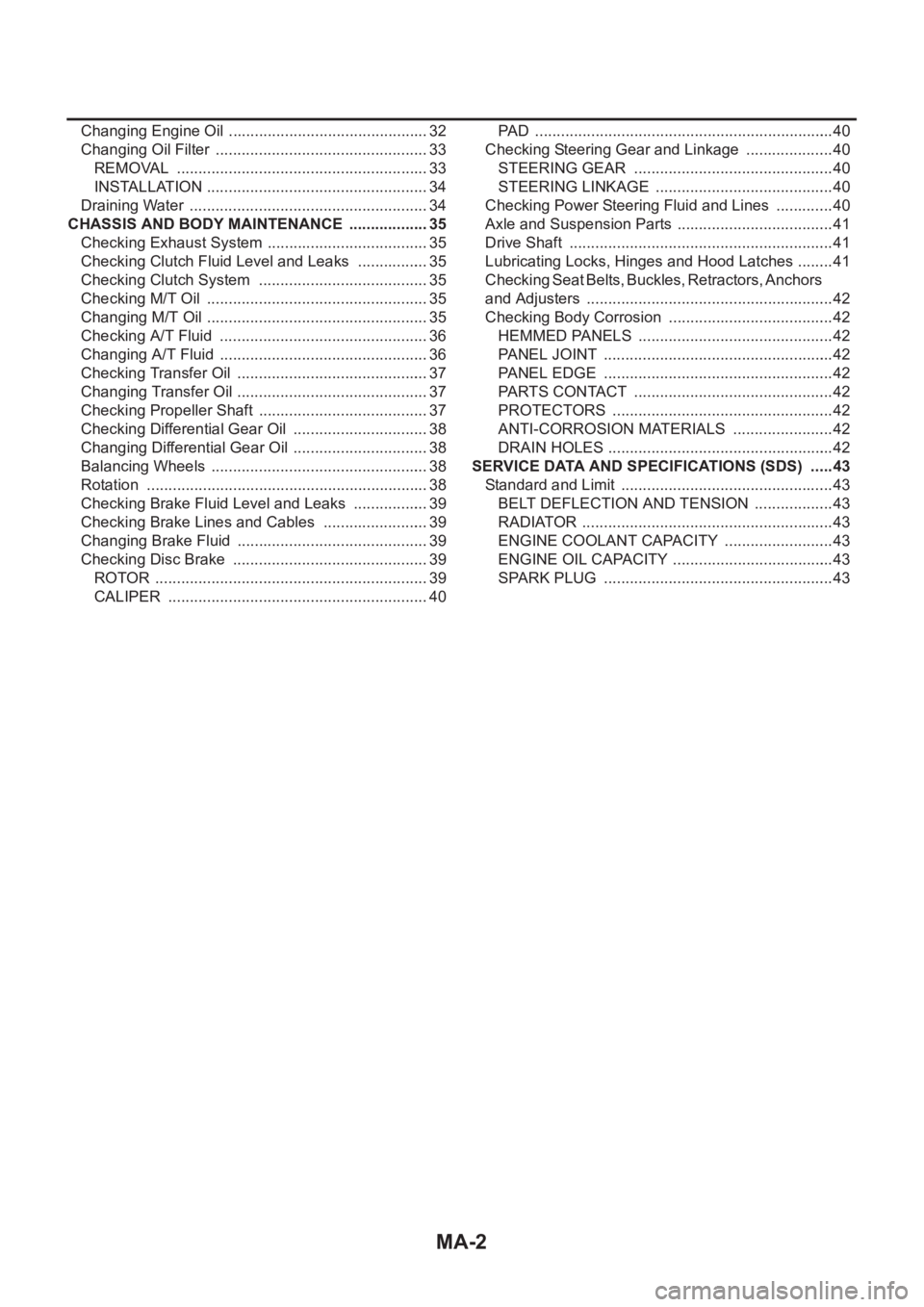
MA-2
Changing Engine Oil ............................................ ... 32
Changing Oil Filter .................................................. 33
REMOVAL ........................................................... 33
INSTALLATION .................................................... 34
Draining Water ........................................................ 34
CHASSIS AND BODY MAINTENANCE ................... 35
Checking Exhaust System ...................................... 35
Checking Clutch Fluid Level and Leaks ................. 35
Checking Clutch System ........................................ 35
Checking M/T Oil .................................................... 35
Changing M/T Oil .................................................... 35
Checking A/T Fluid ................................................. 36
Changing A/T Fluid ................................................. 36
Checking Transfer Oil ............................................. 37
Changing Transfer Oil .......................................... ... 37
Checking Propeller Shaft ........................................ 37
Checking Differential Gear Oil ................................ 38
Changing Differential Gear Oil ................................ 38
Balancing Wheels ................................................... 38
Rotation .................................................................. 38
Checking Brake Fluid Level and Leaks .................. 39
Checking Brake Lines and Cables ......................... 39
Changing Brake Fluid ............................................. 39
Checking Disc Brake .............................................. 39
ROTOR ................................................................ 39
CALIPER ............................................................. 40PAD ...................................................................... 40
Checking Steering Gear and Linkage ..................... 40
STEERING GEAR ............................................... 40
STEERING LINKAGE .......................................... 40
Checking Power Steering Fluid and Lines .............. 40
Axle and Suspension Parts ..................................... 41
Drive Shaft .............................................................. 41
Lubricating Locks, Hinges and Hood Latches ......... 41
Checking Seat Belts, Buckles, Retractors, Anchors
and Adjusters .......................................................... 42
Checking Body Corrosion ....................................... 42
HEMMED PANELS .............................................. 42
PANEL JOINT ...................................................... 42
PANEL EDGE ...................................................... 42
PARTS CONTACT ............................................... 42
PROTECTORS .................................................... 42
ANTI-CORROSION MATERIALS ........................ 42
DRAIN HOLES ..................................................... 42
SERVICE DATA AND SPECIFICATIONS (SDS) ...... 43
Standard and Limit .................................................. 43
BELT DEFLECTION AND TENSION ................... 43
RADIATOR ........................................................... 43
ENGINE COOLANT CAPACITY .......................... 43
ENGINE OIL CAPACITY ...................................... 43
SPARK PLUG ...................................................... 43
Page 3787 of 3833

PERIODIC MAINTENANCE
MA-7
C
D
E
F
G
H
I
J
K
MA
B
MA
PERIODIC MAINTENANCEPFP:00026
Periodic MaintenanceELS000AM
The following tables show the normal maintenance schedule. Depending upon weather and atmospheric con-
ditions, varying road surfaces, individual driving habits and vehicle usage, additional or more frequent mainte-
nance may be required.
Periodic maintenance beyond the last period shown on the tables requires similar maintenance.
ENGINE AND EMISSION CONTROL MAINTENANCE (QR20DE AND QR25DE PETROL ENGINE)
(Annual Mileage <30,000 Km/year)
Abbreviations: I = Inspect and correct or replace as necessary,R = Replace,.
NOTE:
● Maintenance items with “ ” should be performed more frequently according to “Maintenance Under Severe Driving
Conditions”.
●(1)Periodic maintenance is not required. However, if valve noise increases, check valve clearance.
●(2) Replace the drive belts if found damaged or if the auto belt tensioner reading reaches the maximum limit.
●(3) First replace at 90,000 Km (54,000 miles)/60 months, then every 60,000 km (36,000 miles)/48 months. Perform "I"
(Checking the mixture ratio and correcting the mixture ratio if necessary) at the middle of replacement interval.
●(4) Fuel filter is maintenance-free. For service procedures, refer to FL section.
●(5) Perform only according to "Maintenance Under Severe Driving conditions" for models without Euro-OBD system. For
models with Euro-OBD system, periodic maintenance is not required.
CHASSIS AND BODY MAINTENANCE (QR20DE AND QR25DE PETROL ENGINE)
(Annual Mileage <30,000 Km/year)
MAINTENANCE OPERATIONMAINTENANCE INTERVAL
Refer-
ence
page Perform on a kilometer basis, but on an annual
basis when driving less than 15,000 km (9,000
miles) per yearkm x
1,000
(Miles x
1,000)
Months15
(9)
1230
(18)
2445
(27)
3660
(36)
4875
(45)
6090
(54)
72105
(63)
84120
(72)
96
Engine compartment and under vehicle
Intake and exhaust valve clearanceSee
NOTE (1)EM-53
Drive beltsSee
NOTE (2)MA-19
Engine oil (Use recommended oil.)R RRRRRRRMA-23
Engine oil filter (Use NISSAN genuine part or
equivalent)R RRRRRRRMA-23
Engine anti-freeze coolant (Use genuine NISSAN
Anti-Freeze Coolant (L2N) or equivalent.)See
NOTE (3)IRIMA-19
Cooling system II IIIIIIMA-21
Fuel lines I I I IMA-22
Air cleaner filterRRMA-22
Fuel filter (In-tank type)See
NOTE (4)FL-4
Spark plugs R R R RMA-24
EVAP vapor lines (With carbon canister) I I I IEC-425or EC-
111 2
Heated oxygen sensor 1 See
NOTE (5)EC-1320
Page 3789 of 3833

PERIODIC MAINTENANCE
MA-9
C
D
E
F
G
H
I
J
K
MA
B
MA
NOTE:
● Maintenance items with “ ” should be performed more frequently according to “Maintenance Under Severe Driving
Conditions”.
●(1) If valve noise increases, check valve clearance.
●(2) Never use CG-4 oil.
●(3) Oil filter element assembly and O-ring seal are replacement parts.
●(4) First replace at 100,000 Km (60,000 miles)/60 months, then every 60,000Km (36,000 miles)/36 months. After first
replacement, perform "I" (checking the mixture ratio and correcting the mixture ratio if necessary) at the middle of
replacement interval.
●(5) If engine power decreases, black exhaust smoke is emitted or engine noise increases, perform this maintenance item.
CHASSIS AND BODY MAINTENANCE (YD22DDTI DIESEL ENGINE)
(Annual Mileage <30,000 Km/year)
Abbreviations: I = Inspect and correct or replace as necessary,R = Replace, L = Lubricate. Engine oil filter (Use Eco filter or equivalent)See NOTE
(3)RRRRRRMA-33
Engine anti-freeze coolant (Use genuine Nissan Anti-
freeze coolant (L2N) or equivalent)See NOTE
(4)IRMA-27
Cooling system I I I I I IMA-29
Fuel lines I I IMA-30
Air cleaner filter RRMA-32
Fuel filterDRDRDRMA-31
Fuel injectorSee NOTE
(5)EM-144
MAINTENANCE OPERATIONMAINTENANCE INTERVAL
Refer-
ence page Perform either at number of kilometers (miles) or
months, whichever comes first.km x 1,000
(Miles x
1,000)
Months20
(12)
1240
(24)
2460
(36)
3680
(48)
48100
(60)
60120
(72)
72
MAINTENANCE OPERATIONMAINTENANCE INTERVAL
Reference
page Perform either at number of kilometers
(miles) or months, whichever comes first.km x 1,000
(Miles x 1,000)
Months20
(12)
1240
(24)
2460
(36)
3680
(48)
48100
(60)
60120
(72)
72
Underhood and under vehicle
Headlamp aiming IIIIIILT- 6
Brake & clutch, systems and fluid (For level
& leaks)IIIIIIMA-39,MA-35
Brake fluidRRRMA-39
Brake booster vacuum hoses, connections
& check valveIIIBR-19
Power steering fluid & lines (For level &
leaks)IIIIIIMA-40
Manual transaxle gear oil (For level & leaks) IIIIIIMA-35,
Transfer gear oil (For level & leaks) IIIIIIMA-37
Differential gear oil (For level & leaks or
replace)IIRIIRMA-38
Steering gear & linkage, axle & suspension
parts, propeller shaft, front drive shafts &
exhaust systemIIIIIIMA-40,MA-41
,MA-37 ,MA-
41 ,MA-35
Wheel alignment (If necessary, rotate & bal-
ance wheels)IIIIIIFSU-6,MA-38
Page 3792 of 3833

MA-12
PERIODIC MAINTENANCE
NOTE:
● Maintenance items with “ ” should be performed more frequently according to “Maintenance Under Severe Driving
Conditions”.
●(1)Periodic maintenance is not required. However, if valve noise increases, check valve clearance.
●(2) Replace the drive belts if found damaged or if the auto belt tensioner reading reaches the maximum limit.
●(3) First replace at 90,000 Km (54,000 miles), then every 60,000 km (36,000 miles). Perform "I" (Checking the mixture ratio
and correcting the mixture ratio if necessary) at the middle of replacement interval.
●(4) Fuel filter is maintenance-free. For service procedures, refer to FL section.
●(5) Perform only according to "Maintenance Under Severe Driving conditions" for models without Euro-OBD system. For
models with Euro-OBD system, periodic maintenance is not required.
CHASSIS AND BODY MAINTENANCE (QR20DE AND QR25DE PETROL ENGINE)
(Annual Mileage >30,000 Km/year)
Abbreviations: I = Inspect and correct or replace as necessary,R = Replace, L = Lubricate. Cooling system I I I IMA-21
Fuel linesIIMA-22
Air cleaner filterRRMA-22
Fuel filter (In-tank type)See
NOTE (4)FL-4
Spark plugs R R R RMA-24
EVAP vapor lines (With carbon canister) I IEC-111 2 o r
EC-
111 2
Heated oxygen sensor 1 See
NOTE (5)EC-1320
MAINTENANCE OPERATIONMAINTENANCE INTERVAL
Refer-
ence
page Perform on a kilometer basis, but on an annual
basis when driving less than 15,000 km (9.000
miles) per yearkm x
1,000
(Miles x
1,000)
Months15
(9)30
(18)45
(27)60
(36)75
(45)90
(54)105
(63)120
(72)
MAINTENANCE OPERATIONMAINTENANCE INTERVAL
Reference
page Perform either at number of kilometers
(miles) or months, whichever comes
first.km x 1,000
(Miles x 1,000)
Months15
(9)30
(18)45
(27)60
(36)75
(45)90
(54)105
(63)120
(72)
Underhood and under vehicle
Headlamp aiming I I I ILT- 6
Brake & clutch, systems and fluid (For
level & leaks)IIIIMA-35,MA-
39
Brake fluidRRMA-39
Brake booster vacuum hoses, connec-
tions & check valveIIBR-19
Power steering fluid & lines (For level
& leaks)IIIIMA-40
Manual transaxle gear oil (For level &
leaks)IIIIMA-35
Automatic transaxle fluid (For level &
leaks)IIIIMA-36
Transfer gear oil (For level & leaks) I I I IMA-37
Differential gear oil (For level & leaks
or replace)IRIRMA-38,MA-
38
Page 3794 of 3833
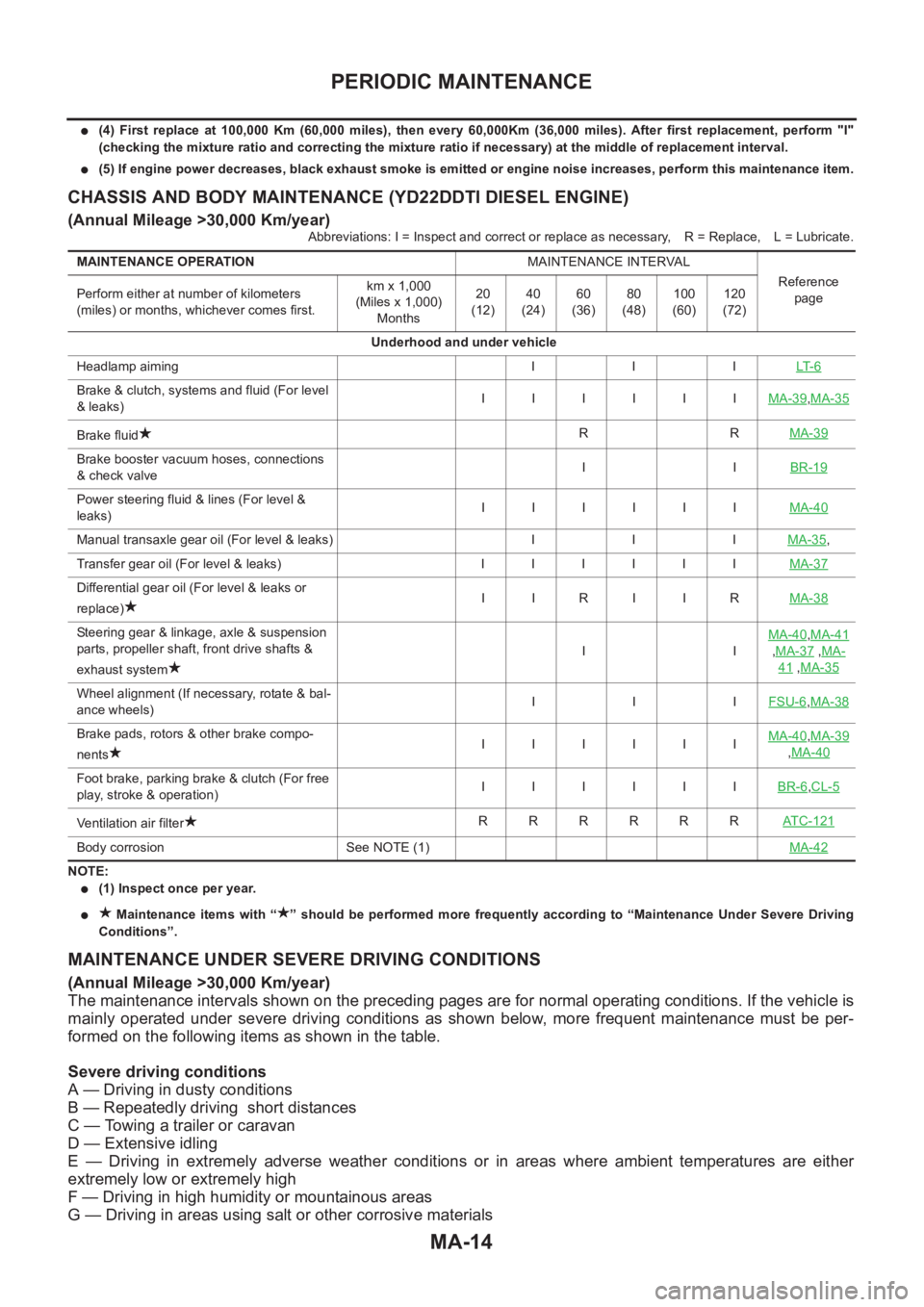
MA-14
PERIODIC MAINTENANCE
●(4) First replace at 100,000 Km (60,000 miles), then every 60,000Km (36,000 miles). After first replacement, perform "I"
(checking the mixture ratio and correcting the mixture ratio if necessary) at the middle of replacement interval.
●(5) If engine power decreases, black exhaust smoke is emitted or engine noise increases, perform this maintenance item.
CHASSIS AND BODY MAINTENANCE (YD22DDTI DIESEL ENGINE)
(Annual Mileage >30,000 Km/year)
Abbreviations: I = Inspect and correct or replace as necessary,R = Replace, L = Lubricate.
NOTE:
●(1) Inspect once per year.
● Maintenance items with “ ” should be performed more frequently according to “Maintenance Under Severe Driving
Conditions”.
MAINTENANCE UNDER SEVERE DRIVING CONDITIONS
(Annual Mileage >30,000 Km/year)
The maintenance intervals shown on the preceding pages are for normal operating conditions. If the vehicle is
mainly operated under severe driving conditions as shown below, more frequent maintenance must be per-
formed on the following items as shown in the table.
Severe driving conditions
A — Driving in dusty conditions
B — Repeatedly driving short distances
C — Towing a trailer or caravan
D — Extensive idling
E — Driving in extremely adverse weather conditions or in areas where ambient temperatures are either
extremely low or extremely high
F — Driving in high humidity or mountainous areas
G — Driving in areas using salt or other corrosive materials
MAINTENANCE OPERATIONMAINTENANCE INTERVAL
Reference
page Perform either at number of kilometers
(miles) or months, whichever comes first.km x 1,000
(Miles x 1,000)
Months20
(12)40
(24)60
(36)80
(48)100
(60)120
(72)
Underhood and under vehicle
Headlamp aiming I I ILT- 6
Brake & clutch, systems and fluid (For level
& leaks)IIIIIIMA-39,MA-35
Brake fluidRRMA-39
Brake booster vacuum hoses, connections
& check valveIIBR-19
Power steering fluid & lines (For level &
leaks)IIIIIIMA-40
Manual transaxle gear oil (For level & leaks) I I IMA-35,
Transfer gear oil (For level & leaks) IIIIIIMA-37
Differential gear oil (For level & leaks or
replace)IIRIIRMA-38
Steering gear & linkage, axle & suspension
parts, propeller shaft, front drive shafts &
exhaust systemIIMA-40,MA-41
,MA-37 ,MA-
41 ,MA-35
Wheel alignment (If necessary, rotate & bal-
ance wheels)IIIFSU-6,MA-38
Brake pads, rotors & other brake compo-
nentsIIIIIIMA-40,MA-39
,MA-40
Foot brake, parking brake & clutch (For free
play, stroke & operation)IIIIIIBR-6,CL-5
Ventilation air filterRRRRRRAT C - 1 2 1
Body corrosion See NOTE (1)MA-42