instrument panel NISSAN X-TRAIL 2001 Service Owner's Manual
[x] Cancel search | Manufacturer: NISSAN, Model Year: 2001, Model line: X-TRAIL, Model: NISSAN X-TRAIL 2001Pages: 3833, PDF Size: 39.49 MB
Page 1495 of 3833

ON BOARD DIAGNOSTIC (OBD) SYSTEM
EC-1145
[QR20(WITHOUT EURO-OBD)]
C
D
E
F
G
H
I
J
K
L
MA
EC
4. 1st trip freeze frame data
5. Others
HOW TO SWITCH DIAGNOSTIC TEST MODE
NOTE:
●It is better to count the time accurately with a clock.
●It is impossible to switch the diagnostic mode when an accelerator pedal position sensor circuit
has a malfunction.
●Always ECM returns to Diagnostic Test Mode I after ignition switch is turned “OFF”.
How to Set Diagnostic Test Mode II (Self-diagnostic Results)
1. Confirm that accelerator pedal is fully released, turn ignition switch “ON” and wait 3 seconds.
2. Repeat the following procedure quickly five times within 5 seconds.
a. Fully depress the accelerator pedal.
b. Fully release the accelerator pedal.
3. Wait 7 seconds, fully depress the accelerator pedal and keep it for approx. 10 seconds until the MI starts
blinking.
4. Fully release the accelerator pedal.
ECM has entered to Diagnostic Test Mode II (Self-diagnostic results).
How to Set Diagnostic Test Mode II (Heated Oxygen Sensor 1 Monitor)
1. Set the ECM in Diagnostic Test Mode II (Self-diagnostic results). Refer to EC-1145, "How to Set Diagnos-
tic Test Mode II (Self-diagnostic Results)" .
2. Start Engine.
ECM has entered to Diagnostic Test Mode II (Heated oxygen sensor 1 monitor).
How to Erase Diagnostic Test Mode II (Self-diagnostic Results)
1. Set ECM in Diagnostic Test Mode II (Self-diagnostic results). Refer to EC-1145, "How to Set Diagnostic
Test Mode II (Self-diagnostic Results)" .
2. Fully depress the accelerator pedal and keep it for more than 10 seconds.
The emission-related diagnostic information has been erased from the backup memory in the ECM.
3. Fully release the accelerator pedal, and confirm the DTC 0000 is displayed.
DIAGNOSTIC TEST MODE I — BULB CHECK
In this mode, the MI on the instrument panel should stay ON. If it remains OFF, check the bulb. Refer to DI-43,
"WARNING LAMPS" or see EC-1265 .
DIAGNOSTIC TEST MODE I — MALFUNCTION WARNING
●These DTC numbers are clarified in Diagnostic Test Mode II (SELF-DIAGNOSTIC RESULTS)
DIAGNOSTIC TEST MODE II — SELF-DIAGNOSTIC RESULTS
In this mode, the DTC and 1st trip DTC are indicated by the number of blinks of the MI as shown below.
The DTC and 1st trip DTC are displayed at the same time. If the MI does not illuminate in diagnostic test mode
I (Malfunction warning), all displayed items are 1st trip DTCs. If only one code is displayed when the MI illumi-
PBIB0092E
MI Condition
ON When the malfunction is detected or the ECM's CPU is malfunctioning.
OFF No malfunction.
Page 1615 of 3833

DTC P0650 MI
EC-1265
[QR20(WITHOUT EURO-OBD)]
C
D
E
F
G
H
I
J
K
L
MA
EC
DTC P0650 MIPFP:24810
Component DescriptionEBS00N72
Malfunction Indicator (MI) is located on the instrument panel. When the ignition switch is turned ON without
engine running, MI will light up. This is a bulb check. When the engine is started, MI should go off. If MI
remains on, the on board diagnostic system has detected an engine system malfunction.
On Board Diagnosis LogicEBS00N73
The MI will not light up for this diagnosis.
FAIL-SAFE MODE
ECM enters fail-safe mode when both DTC P0650 and another DTC, which calls for MI to light up, are
detected at the same time.
DTC Confirmation ProcedureEBS00N74
NOTE:
If “DTC Confirmation Procedure” has been previously conducted, always turn ignition switch “OFF” and wait at
least 10 seconds before conducting the next test.
WITH CONSULT-II
1. Turn ignition switch “ON” and wait at least 1 second.
2. Select “DATA MONITOR” mode with CONSULT-II.
3. Start engine and let it idle for 1 second.
4. If 1st trip DTC is detected, go to EC-1267, "
Diagnostic Proce-
dure" .
Overall Function CheckEBS00N75
Use this procedure to check the overall function of the mass air flow sensor circuit. During this check, a 1st trip
DTC might not be confirmed.
WITHOUT CONSULT-II
1. Turn ignition switch “ON”.
2. Check that the MI is illuminated.
3. If NG, go to EC-1267, "
Diagnostic Procedure" .
If OK, go to next step.
4. Start engine.
5. Check that the MI is not illuminated.
6. If NG, go to EC-1267, "
Diagnostic Procedure" .
DTC No. Trouble diagnosis name DTC detecting condition Possible cause
P0650
0650Malfunction indicator
(MI) control circuit
●An excessively high voltage is sent to ECM
through the MI circuit under the condition
that calls for MI light up.
●An excessively low voltage is sent to ECM
through the MI circuit under the condition
that calls for MI not to light up.
●Harness or connectors
(MI circuit is open or shorted.)
●MI
Detected items Engine operating condition in fail-safe mode
MI circuit Engine speed will not rise more than 2,500 rpm due to the fuel cut
SEF058Y
Page 1757 of 3833

ON BOARD DIAGNOSTIC (OBD) SYSTEM
EC-1407
[YD]
C
D
E
F
G
H
I
J
K
L
MA
EC
Therefore, be sure to receive all keys from vehicle owner. Regarding the procedure of NATS initial-
ization and NATS ignition key ID registration, refer to CONSULT-II operation manual, NATS.
Malfunction Indicator (MI)EBS0036Q
DESCRIPTION
The MI is located on the instrument panel.
1. The MI will light up when the ignition switch is turned ON without
the engine running. This is a bulb check.
●If the MI does not light up, refer to DI-43, "WARNING LAMPS"
or see EC-1573 .
2. When the engine is started, the MI should go off.
If the MI remains on, the on board diagnostic system has
detected an engine system malfunction.
On Board Diagnostic System Function
The on board diagnostic system has the following two functions.
Diagnostic Test Mode I - Bulb Check
In this mode, the MI on the instrument panel should stay ON. If it remains OFF, check the bulb. Refer to DI-43,
"WARNING LAMPS" or see EC-1573 .
Diagnostic Test Mode I - Malfunction Warning
SAT652J
Diagnostic Test
ModeKEY and ENG.
Statu sFunction Explanation of Function
Mode I Ignition switch in
ON position
Engine stoppedBULB CHECK This function checks the MI bulb for damage (blown, open
circuit, etc.).
If the MI does not come on, check MI circuit. (See EC-
1573, "MI& DATA LINK CONNECTORS" .)
Engine running MALFUNCTION
WARNINGThis is a usual driving condition. When ECM detects a mal-
function, the MI will light up to inform the driver that a mal-
function has been detected.
MI Condition
ON When the malfunction is detected or the ECM's CPU is malfunctioning.
OFF No malfunction.
Page 2115 of 3833

ON BOARD DIAGNOSTIC SYSTEM DESCRIPTION
AT-37
[EURO-OBD]
D
E
F
G
H
I
J
K
L
MA
B
AT
ON BOARD DIAGNOSTIC SYSTEM DESCRIPTIONPFP:00000
IntroductionECS004QH
The A/T system has two self-diagnostic systems.
The first is the emission-related on board diagnostic system (EURO-OBD) performed by the TCM in combina-
tion with the ECM. The malfunction is indicated by the MIL (malfunction indicator lamp) and is stored as a DTC
in the ECM memory but not the TCM memory.
The second is the TCM original self-diagnosis indicated by the O/D OFF indicator lamp. The malfunction is
stored in the TCM memory. The detected items are overlapped with EURO-OBD self-diagnostic items. For
detail, refer to AT-42, "
SELF-DIAGNOSTIC RESULT TEST MODE" .
EURO-OBD Function for A/T SystemECS004QI
The ECM provides emission-related on board diagnostic (EURO-OBD) functions for the A/T system. One
function is to receive a signal from the TCM used with EURO-OBD-related parts of the A/T system. The signal
is sent to the ECM when a malfunction occurs in the corresponding EURO-OBD-related part. The other func-
tion is to indicate a diagnostic result by means of the MIL (malfunction indicator lamp) on the instrument panel.
Sensors, switches and solenoid valves are used as sensing elements.
The MIL automatically illuminates in One or Two Trip Detection Logic when a malfunction is sensed in relation
to A/T system parts.
One or Two Trip Detection Logic of EURO-OBDECS004QJ
ONE TRIP DETECTION LOGIC
If a malfunction is sensed during the first test drive, the MIL will illuminate and the malfunction will be stored in
the ECM memory as a DTC. The TCM is not provided with such a memory function.
TWO TRIP DETECTION LOGIC
When a malfunction is sensed during the first test drive, it is stored in the ECM memory as a 1st trip DTC
(diagnostic trouble code) or 1st trip freeze frame data. At this point, the MIL will not illuminate. — First Trip
If the same malfunction as that experienced during the first test drive is sensed during the second test drive,
the MIL will illuminate. — Second Trip
A/T-related parts for which the MIL illuminates during the first or second test drive are listed below.
The “trip” in the “One or Two Trip Detection Logic” means a driving mode in which self-diagnosis is performed
during vehicle operation.
EURO-OBD Diagnostic Trouble Code (DTC)ECS004QK
HOW TO READ DTC AND 1ST TRIP DTC
DTC and 1st trip DTC can be read by the following methods.
( With CONSULT-II or GST) CONSULT-II or GST (Generic Scan Tool) Examples: P0705, P0710,
P0720, P0725, etc.
These DTCs are prescribed by SAE J2012.
(CONSULT-II also displays the malfunctioning component or system.)
●1st trip DTC No. is the same as DTC No.
●Output of the diagnostic trouble code indicates that the indicated circuit has a malfunction. How-
ever, in case of the Mode II and GST they do not indicate whether the malfunction is still occurring
or occurred in the past and returned to normal.
CONSULT-II can identify them as shown below. Therefore, using CONSULT-II (if available) is rec-
ommended.
ItemsMIL
One trip detection Two trip detection
Shift solenoid valve A — DTC: P0750 X
Shift solenoid valve B — DTC: P0755 X
Throttle position sensor — DTC: P1705 X
Except aboveX
Page 2747 of 3833
BRAKE PEDAL
BR-7
C
D
E
G
H
I
J
K
L
MA
B
BR
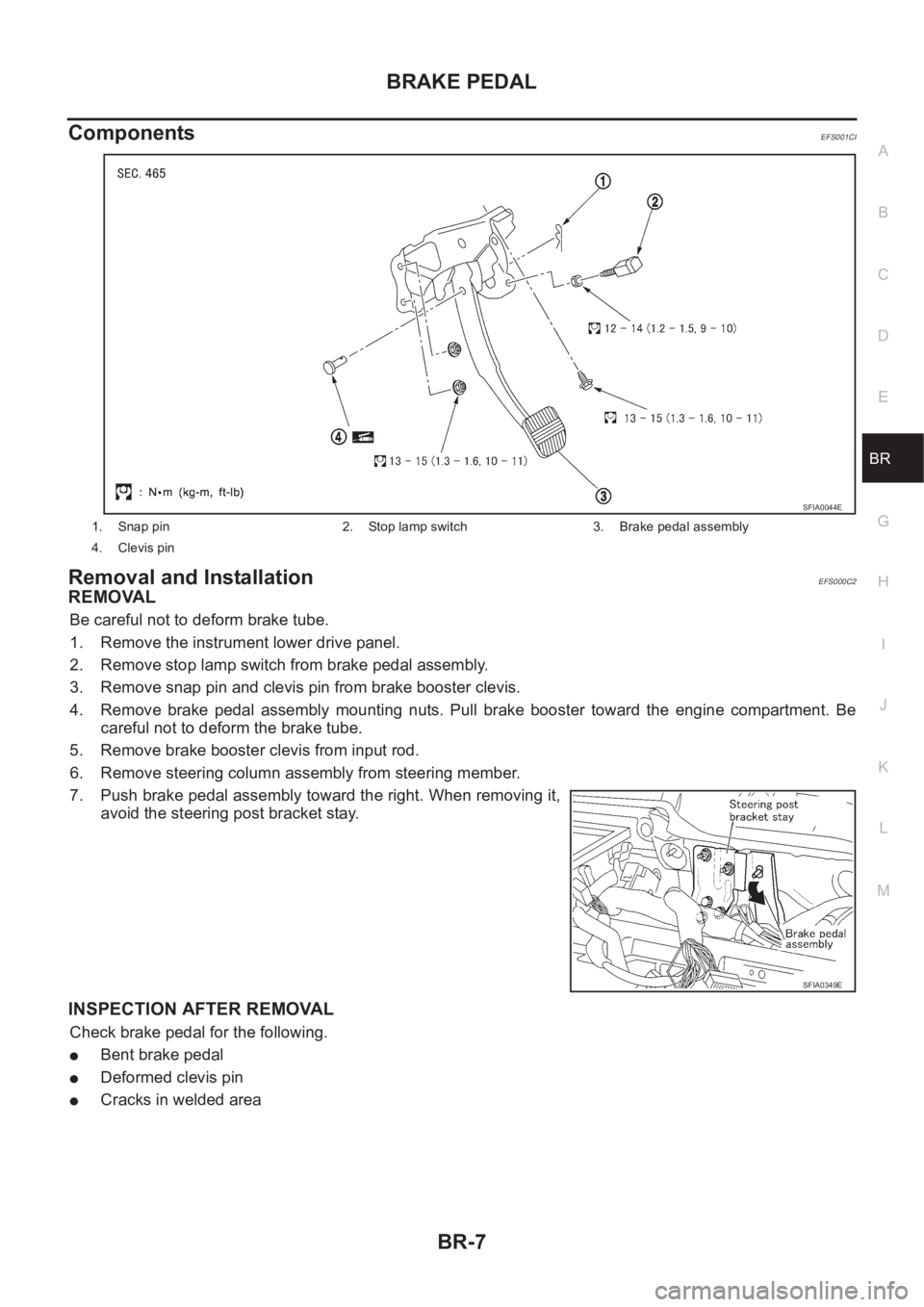
ComponentsEFS001CI
Removal and InstallationEFS000C2
REMOVAL
Be careful not to deform brake tube.
1. Remove the instrument lower drive panel.
2. Remove stop lamp switch from brake pedal assembly.
3. Remove snap pin and clevis pin from brake booster clevis.
4. Remove brake pedal assembly mounting nuts. Pull brake booster toward the engine compartment. Be
careful not to deform the brake tube.
5. Remove brake booster clevis from input rod.
6. Remove steering column assembly from steering member.
7. Push brake pedal assembly toward the right. When removing it,
avoid the steering post bracket stay.
INSPECTION AFTER REMOVAL
Check brake pedal for the following.
●Bent brake pedal
●Deformed clevis pin
●Cracks in welded area
1. Snap pin 2. Stop lamp switch 3. Brake pedal assembly
4. Clevis pin
SFIA0044E
SFIA0349E
Page 2832 of 3833

BRC-48
[4WD/ABS]
4WD/ABS CONTROL UNIT
4WD/ABS CONTROL UNIT
PFP:47660
Removal and InstallationEFS002F7
REMOVAL
1. Remove lower instrument panel and glove box. Refer to IP-3, "INSTRUMENT PANEL ASSEMBLY" .
2. Remove 4WD/ABS control unit.
INSTALLATION
Install in the reverse order of removal.
SFIA1038E
SFIA1039E
Page 2834 of 3833

BRC-50
[4WD/ABS]
G-SENSOR (4WD MODEL ONLY)
G-SENSOR (4WD MODEL ONLY)
PFP:47930
Removal and InstallationEFS001C2
CAUTION:
Be careful not to drop or bump G -sensor because it is sensitive to impact.
1. Remove center console and instrument. Refer to applicable sec-
tion in IP-3, "
INSTRUMENT PANEL ASSEMBLY" .
2. Disconnect G -sensor connector.
3. Remove mounting nuts and remove G -sensor.
Install in the reverse order of removal observing the precautions
above.
SFIA0065E
Page 2909 of 3833

ESP OFF SWITCH
BRC-125
[ESP/TCS/ABS]
C
D
E
G
H
I
J
K
L
MA
B
BRC
ESP OFF SWITCHPFP:25145
Removal and InstallationEFS001CQ
REMOVAL
1. Remove the instrument lower driver panel. Refer to IP-7,
"INSTRUMENT LOWER DRIVER PANEL" .
2. Push the ESP OFF switch's pawls and remove the switch from
the instrument lower driver panel.
INSTALLATION
Installation is the reverse order of removal.
SFIA0390E
Page 2920 of 3833
PS-10
STEERING COLUMN
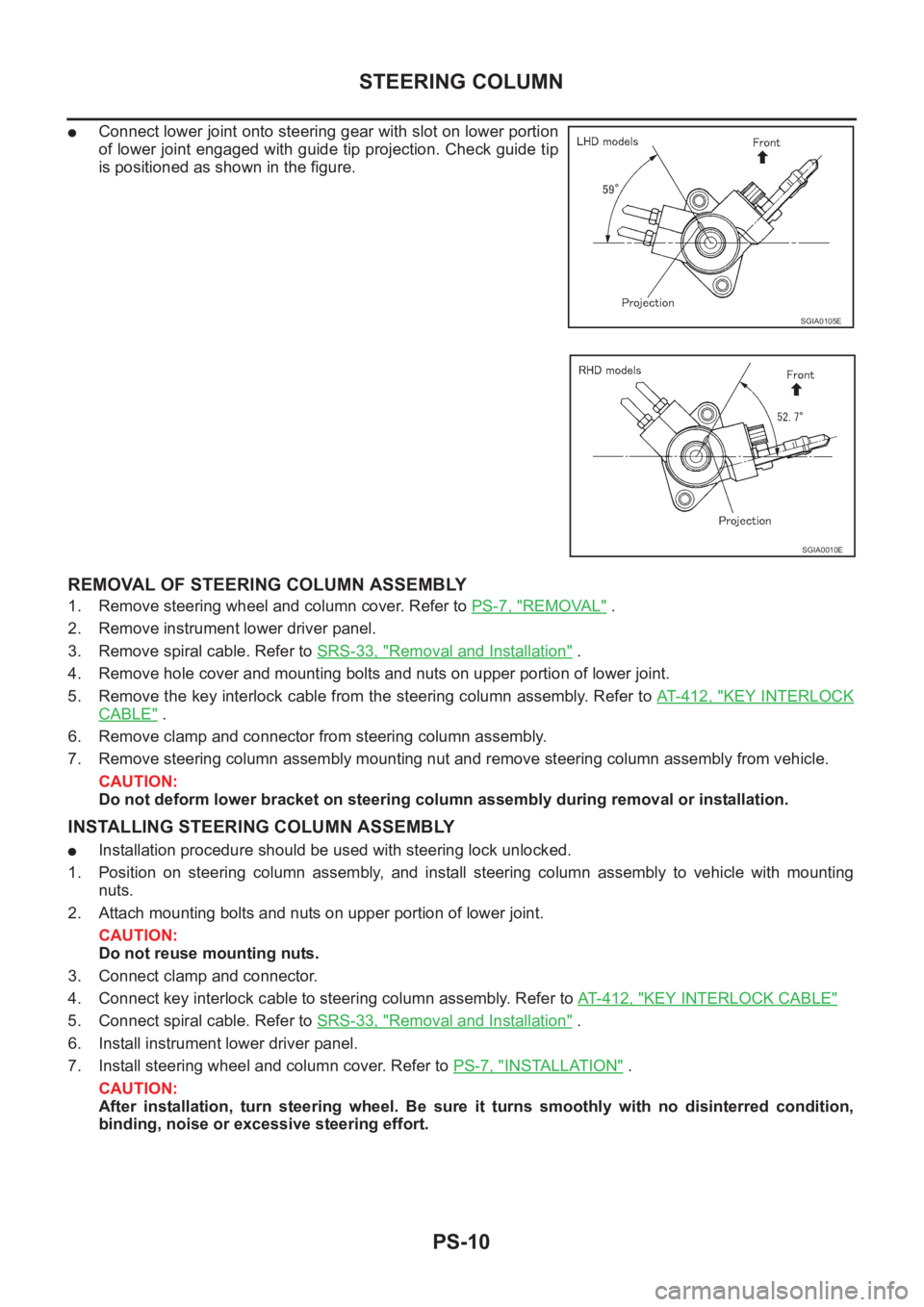
●Connect lower joint onto steering gear with slot on lower portion
of lower joint engaged with guide tip projection. Check guide tip
is positioned as shown in the figure.
REMOVAL OF STEERING COLUMN ASSEMBLY
1. Remove steering wheel and column cover. Refer to PS-7, "REMOVAL" .
2. Remove instrument lower driver panel.
3. Remove spiral cable. Refer to SRS-33, "
Removal and Installation" .
4. Remove hole cover and mounting bolts and nuts on upper portion of lower joint.
5. Remove the key interlock cable from the steering column assembly. Refer to AT- 4 1 2 , "
KEY INTERLOCK
CABLE" .
6. Remove clamp and connector from steering column assembly.
7. Remove steering column assembly mounting nut and remove steering column assembly from vehicle.
CAUTION:
Do not deform lower bracket on steering column assembly during removal or installation.
INSTALLING STEERING COLUMN ASSEMBLY
●Installation procedure should be used with steering lock unlocked.
1. Position on steering column assembly, and install steering column assembly to vehicle with mounting
nuts.
2. Attach mounting bolts and nuts on upper portion of lower joint.
CAUTION:
Do not reuse mounting nuts.
3. Connect clamp and connector.
4. Connect key interlock cable to steering column assembly. Refer to AT- 4 1 2 , "
KEY INTERLOCK CABLE"
5. Connect spiral cable. Refer to SRS-33, "Removal and Installation" .
6. Install instrument lower driver panel.
7. Install steering wheel and column cover. Refer to PS-7, "
INSTALLATION" .
CAUTION:
After installation, turn steering wheel. Be sure it turns smoothly with no disinterred condition,
binding, noise or excessive steering effort.
SGIA0105E
SGIA0010E
Page 3005 of 3833
PRECAUTIONS
SRS-3
C
D
E
F
G
I
J
K
L
MA
B
SRS
PRECAUTIONSPFP:00001
Precautions for Supplemental Restraint System (SRS) “AIR BAG” and “SEAT
BELT PRE-TENSIONER”
EHS000QI
The Supplemental Restraint System such as “AIR BAG” and “SEAT BELT PRE-TENSIONER”, used along
with a front seat belt, helps to reduce the risk or severity of injury to the driver and front passenger for certain
types of collision. Information necessary to service the system safely is included in the SRS and SB section of
this Service Manual.
WARNING:
●To avoid rendering the SRS inoperative, which could increase the risk of personal injury or death
in the event of a collision which would result in air bag inflation, all maintenance must be per-
formed by an authorized NISSAN/INFINITI dealer.
●Improper maintenance, including incorrect removal and installation of the SRS, can lead to per-
sonal injury caused by unintentional activation of the system. For removal of Spiral Cable and Air
Bag Module, see the SRS section.
●Do not use electrical test equipment on any circuit related to the SRS unless instructed to in this
Service Manual. SRS wiring harnesses can be identified by yellow and/or orange harness connec-
tors.
Precautions for SRS “AIR BAG” and “SEAT BELT PRE-TENSIONER” ServiceEHS000BH
●Do not use electrical test equipment to check SRS circuits unless instructed to in this Service Manual.
●Before servicing the SRS, turn ignition switch “OFF”, disconnect both battery cables and wait at least 3
minutes.
For approximately 3 minutes after the cables is removed, it is still possible for the air bag and seat belt
pre-tensioner to deploy. Therefore, do not work on any SRS connectors or wires until at least 3 minutes
have passed.
●Diagnosis sensor unit must always be installed with their arrow marks “⇐” pointing towards the front of the
vehicle for proper operation. Also check diagnosis sensor unit for cracks, deformities or rust before instal-
lation and replace as required.
●The spiral cable must be aligned with the neutral position since its rotations are limited. Do not attempt to
turn steering wheel or column after removal of steering gear.
●Handle air bag module carefully. Always place driver and front passenger air bag modules with the pad
side facing upward and place front side air bag module standing with stud bolt side setting bottom.
●Conduct self-diagnosis to check entire SRS for proper function after replacing any components.
●After air bag inflates, the front instrument panel assembly should be replaced if damaged.
Trouble Diagnosis PrecautionEHS000BI
When you read wiring diagrams, refer to the followings:
●“HOW TO READ WIRING DIAGRAMS” in GI section
●PG-2, "POWER SUPPLY ROUTING" in PG section
When you perform trouble diagnosis, refer to the followings:
●“HOW TO FOLLOW TEST GROUP IN TROUBLE DIAGNOSIS” in GI section
●“HOW TO PERFORM EFFICIENT DIAGNOSIS FOR AN ELECTRICAL INCIDENT” in GI section
Check for any service bulletins before servicing the vehicle.