NISSAN X-TRAIL 2001 Service Workshop Manual
X-TRAIL 2001
NISSAN
NISSAN
https://www.carmanualsonline.info/img/5/57405/w960_57405-0.png
NISSAN X-TRAIL 2001 Service Workshop Manual
Page 3404 of 3833
ATC-128
DUCTS AND GRILLES
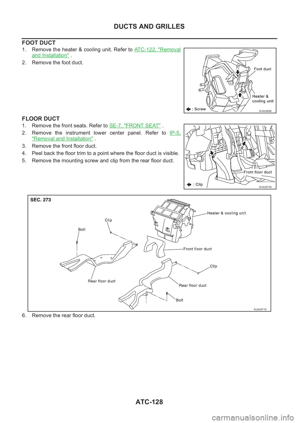
FOOT DUCT
1. Remove the heater & cooling unit. Refer to ATC-122, "Removal
and Installation" .
2. Remove the foot duct.
FLOOR DUCT
1. Remove the front seats. Refer to SE-7, "FRONT SEAT" .
2. Remove the instrument lower center panel. Refer to IP-5,
"Removal and Installation" .
3. Remove the front floor duct.
4. Peel back the floor trim to a point where the floor duct is visible.
5. Remove the mounting screw and clip from the rear floor duct.
6. Remove the rear floor duct.
RJIA0069E
RJIA0070E
RJIA0071E
Page 3450 of 3833
MTC-24
HEATER UNIT
HEATER UNIT
PFP:27100
Removal and InstallationEJS001F9
REMOVAL
1. Drain coolant from cooling system.
2. Disconnect two heater hoses from heater core pipe.
3. Remove the instrument panel.
4. Remove the blower unit.
5. Remove the clips of vehicle harness from steering member.
6. Remove the instrument stay.
NOTE:
This illustration is for RHD models. The layout for LHD models is symmetrically opposite.
RJIA0060E
RJIA0061E
RJIA0062E
Page 3455 of 3833
DUCTS AND GRILLES
MTC-29
C
D
E
F
G
H
I
K
L
MA
B
MTC
DUCTS AND GRILLESPFP:27860
Removal and InstallationEJS000XW
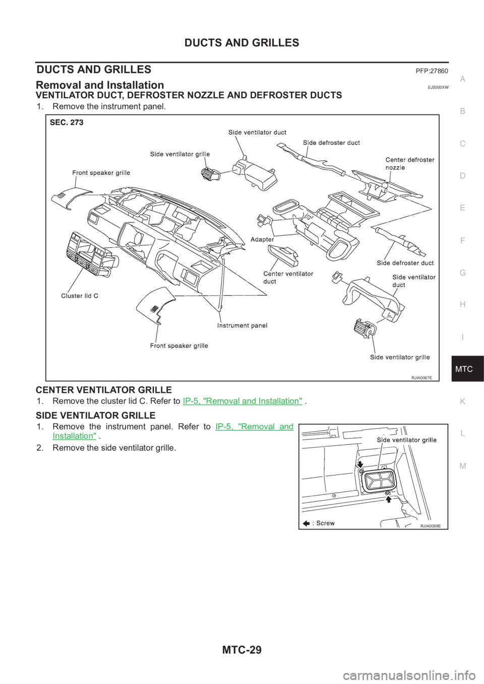
VENTILATOR DUCT, DEFROSTER NOZZLE AND DEFROSTER DUCTS
1. Remove the instrument panel.
CENTER VENTILATOR GRILLE
1. Remove the cluster lid C. Refer to IP-5, "Removal and Installation" .
SIDE VENTILATOR GRILLE
1. Remove the instrument panel. Refer to IP-5, "Removal and
Installation" .
2. Remove the side ventilator grille.
RJIA0067E
RJIA0068E
Page 3456 of 3833
MTC-30
DUCTS AND GRILLES
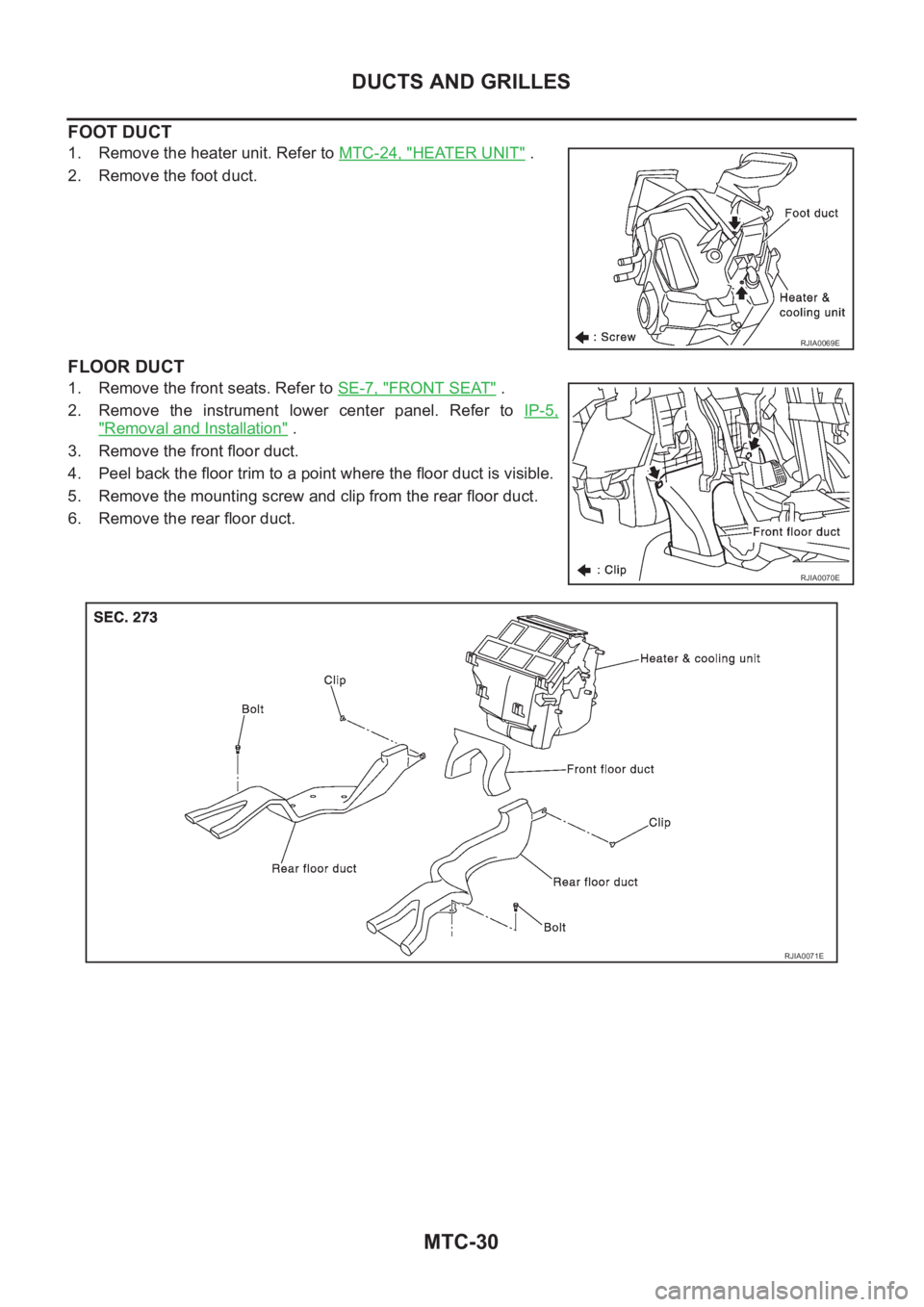
FOOT DUCT
1. Remove the heater unit. Refer to MTC-24, "HEATER UNIT" .
2. Remove the foot duct.
FLOOR DUCT
1. Remove the front seats. Refer to SE-7, "FRONT SEAT" .
2. Remove the instrument lower center panel. Refer to IP-5,
"Removal and Installation" .
3. Remove the front floor duct.
4. Peel back the floor trim to a point where the floor duct is visible.
5. Remove the mounting screw and clip from the rear floor duct.
6. Remove the rear floor duct.
RJIA0069E
RJIA0070E
RJIA0071E
Page 3506 of 3833
LT-16
HEADLAMP AIMING CONTROL
Removal and Installation
EKS003CA
1. Remove the Instrument lower driver panel . Refer to IP-5,
"Removal and Installation" in “INSTRUMENT PANEL (IP)” sec-
tion.
2. Press the headlamp aiming switch fixing pawls and remove it
from the Instrument lower driver panel.
Switch Circuit InspectionEKS003CB
Using a circuit tester, check continuity between the headlamp aiming
switch connector terminals in each operation status of the aiming
switch.
SKIA4167E
SKIA1168E
Page 3515 of 3833
HAZARD SWITCH
LT-25
C
D
E
F
G
H
I
J
L
MA
B
LT
HAZARD SWITCHPFP:25290
Removal and Installation EKS003BZ
REMOVAL
1. Remove Instrument lower center panel. Refer to IP-3, "INSTRU-
MENT PANEL ASSEMBLY" .in “INSTRUMENT PANEL (IP)”
section.
2. Using a flat-bladed screwdriver or other suitable tool, press pawl
to remove hazard switch from Instrument lower center panel.
INSTALLATION
Installation is in the reverse order of removal.
SKIA0061E
Page 3581 of 3833
COMBINATION METERS (LHD MODELS)
DI-23
C
D
E
F
G
H
I
J
L
MA
B
DI
Removal and Installation for Combination MeterEKS002ZO
1. Remove the cluster lid A. Refer toIP-3, "INSTRUMENT PANEL
ASSEMBLY" .
2. Remove the screws (4), and pull out combination meter.
3. Disconnect connectors and remove combination meter.
Disassembly and Assembly for Combination MeterEKS002ZP
1. Disengaged the tabs(8) to separate front cover.
2. Remove finisher.
3. Remove bulbs.
SKIA0036E
SKIA0044E
Page 3600 of 3833
DI-42
COMBINATION METERS (RHD MODELS)
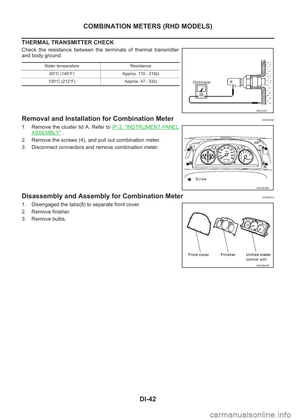
THERMAL TRANSMITTER CHECK
Check the resistance between the terminals of thermal transmitter
and body ground.
Removal and Installation for Combination MeterEKS0030Z
1. Remove the cluster lid A. Refer to IP-3, "INSTRUMENT PANEL
ASSEMBLY" .
2. Remove the screws (4), and pull out combination meter.
3. Disconnect connectors and remove combination meter.
Disassembly and Assembly for Combination MeterEKS00310
1. Disengaged the tabs(8) to separate front cover.
2. Remove finisher.
3. Remove bulbs.
Water temperature Resistance
60°C (140°F) Approx. 170 - 210Ω
100°C (212°F) Approx. 47 - 53Ω
MEL424F
SKIA0036E
SKIA0044E
Page 3654 of 3833
WW-26
CIGARETTE LIGHTER
Removal and Installation
EKS0033D
REMOVAL
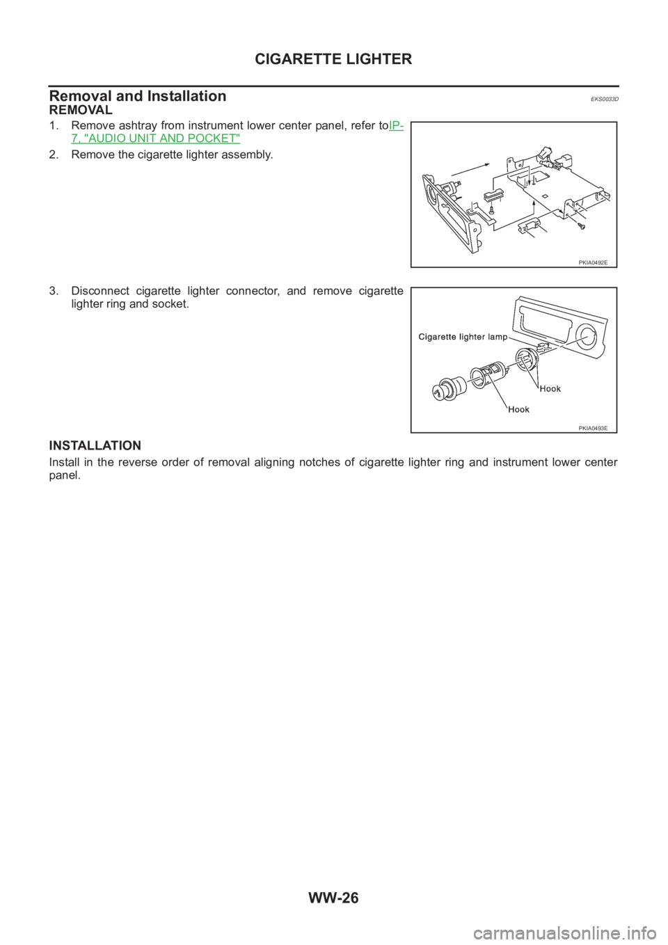
1. Remove ashtray from instrument lower center panel, refer toIP-
7, "AUDIO UNIT AND POCKET"
2. Remove the cigarette lighter assembly.
3. Disconnect cigarette lighter connector, and remove cigarette
lighter ring and socket.
INSTALLATION
Install in the reverse order of removal aligning notches of cigarette lighter ring and instrument lower center
panel.
PKIA0492E
PKIA0493E
Page 3656 of 3833
WW-28
POWER SOCKET
Removal and Installation for Front Power Socket
EKS0036F
REMOVAL
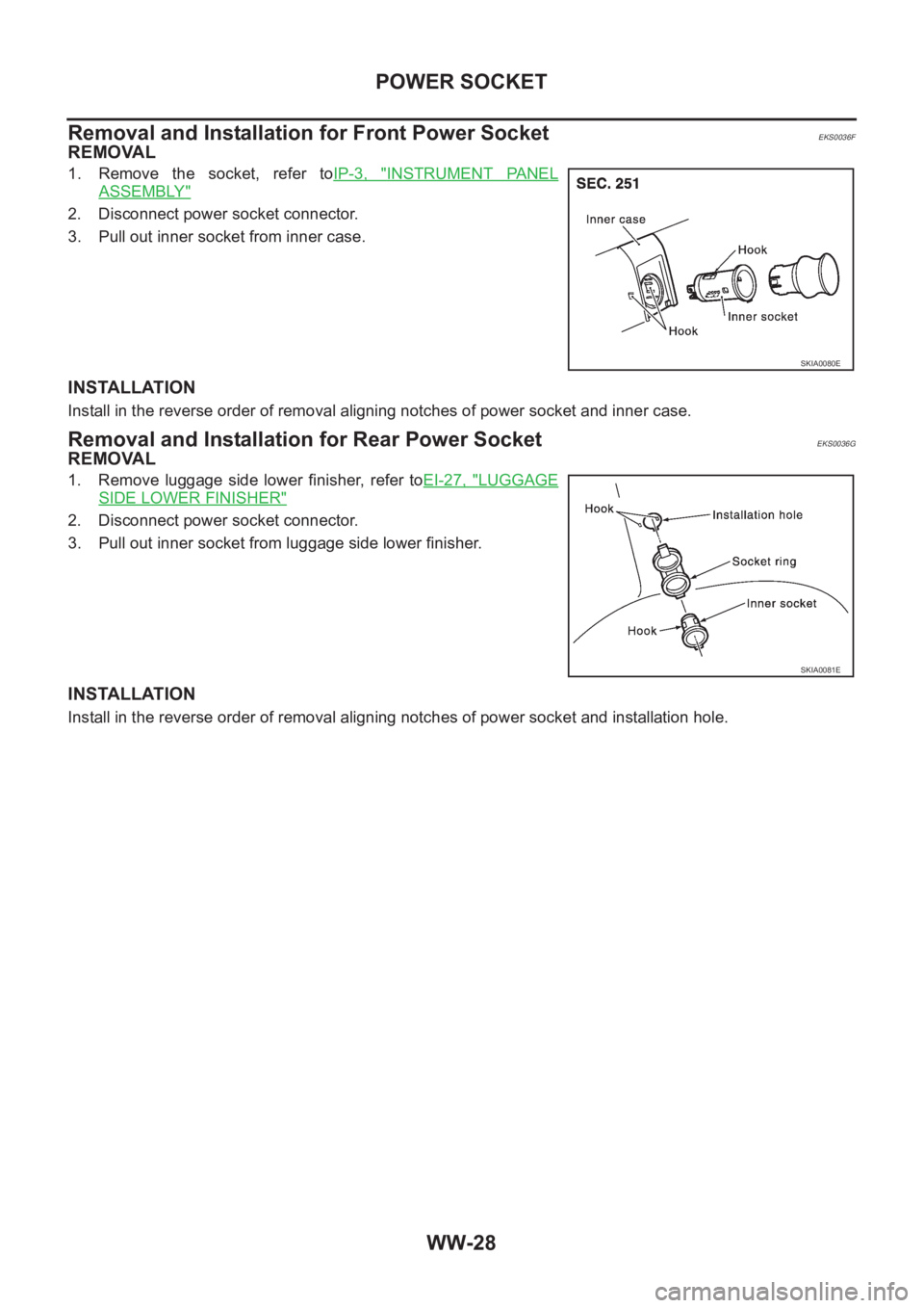
1. Remove the socket, refer toIP-3, "INSTRUMENT PANEL
ASSEMBLY"
2. Disconnect power socket connector.
3. Pull out inner socket from inner case.
INSTALLATION
Install in the reverse order of removal aligning notches of power socket and inner case.
Removal and Installation for Rear Power SocketEKS0036G
REMOVAL
1. Remove luggage side lower finisher, refer toEI-27, "LUGGAGE
SIDE LOWER FINISHER"
2. Disconnect power socket connector.
3. Pull out inner socket from luggage side lower finisher.
INSTALLATION
Install in the reverse order of removal aligning notches of power socket and installation hole.
SKIA0080E
SKIA0081E