seat adjustment NISSAN X-TRAIL 2001 Service Repair Manual
[x] Cancel search | Manufacturer: NISSAN, Model Year: 2001, Model line: X-TRAIL, Model: NISSAN X-TRAIL 2001Pages: 3833, PDF Size: 39.49 MB
Page 52 of 3833

EM-2
TIMING CHAIN .......................................................... 37
Removal and Installation ........................................ 37
REMOVAL ........................................................... 38
INSPECTION AFTER REMOVAL ........................ 41
INSTALLATION .................................................... 41
CAMSHAFT ............................................................... 46
Removal and Installation ........................................ 46
REMOVAL ........................................................... 46
INSTALLATION .................................................... 48
INSPECTION AFTER REMOVAL ........................ 51
Valve Clearance ...................................................... 53
INSPECTION ....................................................... 53
ADJUSTMENT .................................................... 54
OIL SEAL .................................................................. 56
Removal and Installation of Valve Oil Seal ............. 56
REMOVAL ........................................................... 56
INSTALLATION .................................................... 56
Removal and Installation of Front Oil Seal ............. 56
REMOVAL ........................................................... 56
INSTALLATION .................................................... 57
Removal and Installation of Rear Oil Seal .............. 57
REMOVAL ........................................................... 57
INSTALLATION .................................................... 57
CYLINDER HEAD .................................................. ... 59
On-Vehicle Service ................................................. 59
CHECKING COMPRESSION PRESSURE ......... 59
Removal and Installation ........................................ 60
REMOVAL ........................................................... 60
INSPECTION AFTER REMOVAL ........................ 61
INSTALLATION .................................................... 61
Disassembly and Assembly .................................... 62
DISASSEMBLY ................................................... 63
ASSEMBLY ......................................................... 63
Inspection After Disassembly ................................. 64
CYLINDER HEAD DISTORTION ........................ 64
VALVE DIMENSIONS .......................................... 64
VALVE GUIDE CLEARANCE .............................. 65
VALVE GUIDE REPLACEMENT ......................... 65
VALVE SEAT CONTACT ..................................... 66
VALVE SEAT REPLACEMENT ........................... 66
VALVE SPRING SQUARENESS ......................... 67
VALVE SPRING DIMENSIONS AND VALVE
SPRING PRESSURE LOAD ............................... 68
ENGINE ASSEMBLY ................................................ 69
Removal and Installation ........................................ 69
REMOVAL .......................................................
.... 69
INSTALLATION .................................................... 71
INSPECTION AFTER INSTALLATION ................ 71
CYLINDER BLOCK ................................................... 73
Disassembly and Assembly .................................... 73
DISASSEMBLY ................................................... 74
ASSEMBLY ......................................................... 78
How to Select Piston and Bearing .......................... 82
DESCRIPTION .................................................... 82
HOW TO SELECT PISTON ................................. 83
HOW TO SELECT CONNECTING ROD BEAR-
ING ...................................................................... 83HOW TO SELECT MAIN BEARING .................... 85
Inspection After Disassembly .................................. 88
CRANKSHAFT END PLAY .................................. 88
CONNECTING ROD SIDE CLEARANCE ........... 89
PISTON AND PISTON PIN CLEARANCE ........... 89
PISTON RING SIDE CLEARANCE ..................... 90
PISTON RING END GAP .................................... 90
CONNECTING ROD BEND AND TORSION ....... 91
CONNECTING ROD BEARING (BIG END) ........ 91
CONNECTING ROD BUSHING OIL CLEAR-
ANCE (SMALL END) ........................................... 91
CYLINDER BLOCK DISTORTION ...................... 92
INNER DIAMETER OF MAIN BEARING HOUS-
ING ....................................................................... 93
PISTON TO CYLINDER BORE CLEARANCE .... 93
OUTER DIAMETER OF CRANKSHAFT JOUR-
NAL ...................................................................... 94
OUTER DIAMETER OF CRANKSHAFT PIN ...... 94
OUT-OF-ROUND AND TAPER OF CRANK-
SHAFT ................................................................. 94
CRANKSHAFT RUNOUT .................................... 95
CONNECTING ROD BEARING OIL CLEAR-
ANCE ................................................................... 95
MAIN BEARING OIL CLEARANCE ..................... 95
MAIN BEARING CRUSH HEIGHT ...................... 96
OUTER DIAMETER OF LOWER CYLINDER
BLOCK MOUNTING BOLT .................................. 96
OUTER DIAMETER OF CONNECTING ROD
BOLT .................................................................... 96
MOVEMENT AMOUNT OF FLYWHEEL (M/T
MODELS) ............................................................. 97
SERVICE DATA AND SPECIFICATIONS (SDS) ...... 98
Standard and Limit .................................................. 98
GENERAL SPECIFICATIONS ............................. 98
DRIVE BELTS ...................................................... 98
INTAKE MANIFOLD AND EXHAUST MANI-
FOLD ................................................................... 98
SPARK PLUG ...................................................... 98
CYLINDER HEAD ................................................ 98
VALVE .................................................................. 99
CAMSHAFT AND CAMSHAFT BEARING .........102
CYLINDER BLOCK ............................................102
PISTON, PISTON RING AND PISTON PIN .....
.103
CONNECTING ROD ..........................................104
CRANKSHAFT ...................................................105
MAIN BEARING .................................................106
CONNECTING ROD BEARING .........................107
Tightening Torque .................................................108
YD22DDTi
PRECAUTIONS .......................................................110
Precautions for Drain Engine Coolant ...................110
Precautions for Disconnecting Fuel Piping ...........110
Precautions for Removal and Disassembly ..........110
Precautions for Inspection, Repair and Replace-
ment ......................................................................110
Precautions for Assembly and Installation ............110
Page 1968 of 3833
CL-10
CLUTCH MASTER CYLINDER
REMOVAL
1. Using one of the following methods, remove hose from the nipple.
●Drain clutch fluid from reservoir tank and remove hose.
●Remove hose from the nipple. Immediately plug hose and reservoir tank to prevent clutch fluid from
dripping.
CAUTION:
Do not spill clutch fluid onto painted surfaces. If it spills, wipe up immediately and wash the
affected area with water.
2. Using a flare nut wrench, remove clutch tube.
3. Remove snap pin and clevis pin on clevis in passenger compartment to separate clutch pedal.
4. First remove the mounting nuts on the master cylinder assembly, and then the master cylinder assembly
from the vehicle.
INSTALLATION
1. Connect clutch tube to master cylinder assembly and temporarily tighten flare nut.
2. Install master cylinder assembly and tighten mounting nut to the specified torque.
3. Using a flare nut torque wrench, tighten clutch tube flare nut to the specified torque.
4. Attach clevis of the clevis pin to the clutch pedal.
5. Attach snap pin to the clevis pin.
6. Install hose to the nipple.
7. After completing this procedure, inspect and adjust pedal height and then bleed the clutch tube.
●Refer to CL-5, "On-Vehicle Inspection and Adjustment" , CL-8, "Air Bleeding Procedure" .
Disassembly and AssemblyECS008BB
DISASSEMBLY
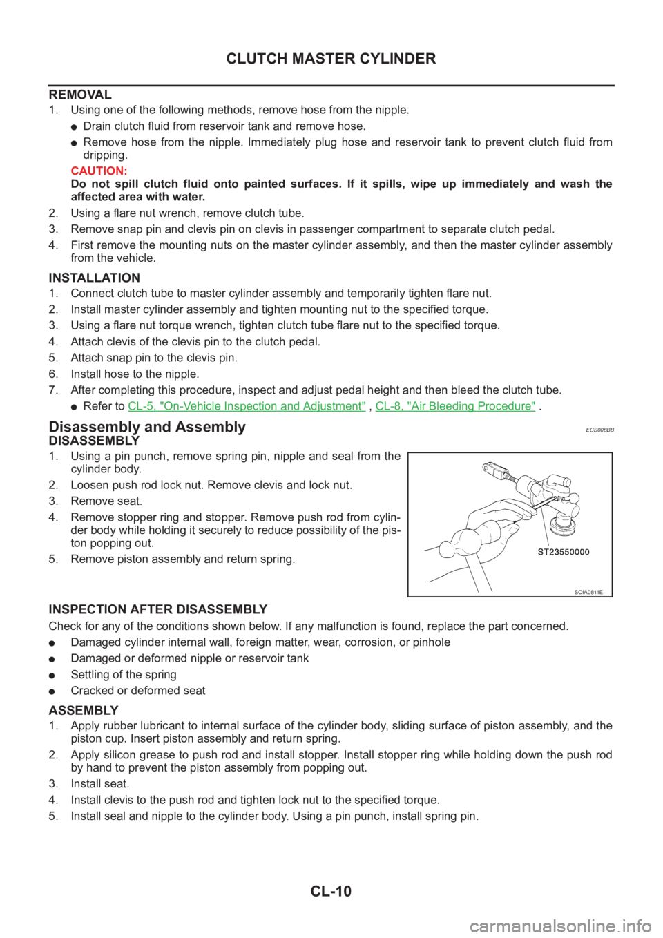
1. Using a pin punch, remove spring pin, nipple and seal from the
cylinder body.
2. Loosen push rod lock nut. Remove clevis and lock nut.
3. Remove seat.
4. Remove stopper ring and stopper. Remove push rod from cylin-
der body while holding it securely to reduce possibility of the pis-
ton popping out.
5. Remove piston assembly and return spring.
INSPECTION AFTER DISASSEMBLY
Check for any of the conditions shown below. If any malfunction is found, replace the part concerned.
●Damaged cylinder internal wall, foreign matter, wear, corrosion, or pinhole
●Damaged or deformed nipple or reservoir tank
●Settling of the spring
●Cracked or deformed seat
ASSEMBLY
1. Apply rubber lubricant to internal surface of the cylinder body, sliding surface of piston assembly, and the
piston cup. Insert piston assembly and return spring.
2. Apply silicon grease to push rod and install stopper. Install stopper ring while holding down the push rod
by hand to prevent the piston assembly from popping out.
3. Install seat.
4. Install clevis to the push rod and tighten lock nut to the specified torque.
5. Install seal and nipple to the cylinder body. Using a pin punch, install spring pin.
SCIA0811E
Page 2639 of 3833

TRANSFER ASSEMBLY
TF-29
C
E
F
G
H
I
J
K
L
MA
B
TF
8. Using a drift and press, press in the companion flange.
9. Apply anti-corrosion oil onto threads and seat of the pinion nut
and adjust the pinion nut tightening torque and pinion bearing
preload torque (P’
1 ).
CAUTION:
●Discard the old pinion nut; replace with new ones.
●Adjust the lower limit of the pinion nut tightening torque first.
●If specified preload torque is exceeded, replace the collapsible spacer and tighten again. Never
loosen the pinion nut for further preload torque adjustment.
●After the adjustment, rotate the companion flange back and forth in 2 to 3 times to check for
abnormal noise, rotation malfunction, and other malfunctions.
10. Apply multi-purpose grease lightly and evenly onto an O-ring, and install it to the pinion sleeve.
CAUTION:
Discard the old O-ring; replace with new one.
11. Assemble the selected pinion sleeve shim.
12. Install the pinion sleeve assembly, and apply anti-corrosive oil onto threads and seats on the mounting
bolts. Tighten to the specified torque.
13. Check backlash, preload torque, tooth contact, and companion flange runout.
●TF-14, "Assembly Inspection".
The overall preload torque is as follows:Pinion nut tightening torque
: 128 - 294 N·m (13 - 30 kg-m, 94 - 216 ft-lb)
Pinion bearing preload torque (P’
1 )
: 0.40 - 0.78 N·m (0.04 - 0.08 kg-m, 4 - 6 in-lb)
Tightening torque : 26 - 33 N·m (2.6 - 3.4 kg-m, 19 - 24 ft-lb)
Overall preload torque
With all oil seals installed : P’
1 +0.45 - 0.47 N·m (0.045 - 0.048 kg-m, 3.9- 4.1 in-lb)
Without transfer case oil seal and ring gear oil seal
: P’
1 + 0 . 3 5 - 0 . 3 7 N · m ( 0 . 0 3 5 - 0 . 0 3 8 k g - m , 3 . 1 - 3 . 2 i n - l b )
SDIA0552E
Page 2741 of 3833

BR-1
BRAKE SYSTEM
F BRAKES
CONTENTS
C
D
E
G
H
I
J
K
L
M
SECTION
A
B
BR
BRAKE SYSTEM
PRECAUTIONS .......................................................... 3
Precautions for Supplemental Restraint System
(SRS) “AIR BAG” and “SEAT BELT PRE-TEN-
SIONER” .................................................................. 3
Precautions for Brake System .................................. 3
PREPARATION ........................................................... 4
Special Service Tools ............................................... 4
Commercial Service Tools ........................................ 4
NOISE, VIBRATION, AND HARSHNESS (NVH)
TROUBLESHOOTING ................................................ 5
NVH Troubleshooting Chart ..................................... 5
BRAKE PEDAL .......................................................... 6
On-Vehicle Inspection and Adjustment .................... 6
Components ............................................................. 7
Removal and Installation .......................................... 7
REMOVAL ............................................................. 7
INSPECTION AFTER REMOVAL ......................... 7
INSTALLATION ..................................................... 8
BRAKE FLUID ............................................................ 9
Checking Brake Fluid Level ..................................... 9
Checking Brake Line ................................................ 9
Changing Brake Fluid ............................................... 9
Brake Burnishing Procedure .................................. 10
Bleeding Brake System .......................................... 10
BRAKE PIPING AND HOSE .....................................11
Hydraulic Piping ...................................................... 11
Removal and Installation of Front Brake Piping and
Brake Hose ............................................................. 11
REMOVAL ............................................................ 11
INSTALLATION .................................................... 11
Removal and Installation of Rear Brake Piping and
Brake Hose ............................................................ 12
REMOVAL ........................................................... 12
INSTALLATION ................................................... 12
Inspection ............................................................... 12
BRAKE MASTER CYLINDER .................................. 13
Components ........................................................... 13
Removal and Installation ........................................ 13
REMOVAL ........................................................... 13INSTALLATION ................................................... 13
Disassembly and Assembly .................................... 14
DISASSEMBLY ................................................... 14
INSPECTION AFTER REMOVAL ....................... 14
ASSEMBLY ......................................................... 15
BRAKE BOOSTER ................................................... 17
On-Vehicle Inspection and Service ......................... 17
FUNCTION INSPECTION ................................... 17
AIRTIGHTNESS INSPECTION ........................... 17
Removal and Installation ........................................ 17
REMOVAL ........................................................... 17
INSPECTION AFTER REMOVAL ....................... 18
INSTALLATION ................................................... 18
VACUUM LINES ....................................................... 19
Removal and Installation ........................................ 19
Inspection ............................................................... 19
VISUAL INSPECTION ......................................... 19
CHECK VALVE INSPECTION ............................. 20
FRONT DISC BRAKE ............................................... 21
Component ............................................................. 21
Inspection ............................................................... 21
PAD THICKNESS ................................................ 21
Pad Replacement ................................................ ... 22
REMOVAL ........................................................... 22
INSTALLATION ................................................... 22
Caliper Removal and Installation ............................ 22
REMOVAL ........................................................... 22
INSTALLATION ................................................... 23
Caliper Disassembly and Assembly ....................... 23
DISASSEMBLY ................................................... 23
INSPECTION AFTER DISASSEMBLY ................ 23
DISC ROTOR INSPECTION ............................... 24
ASSEMBLY ......................................................... 24
BRAKE BURNISHING PROCEDURE ................. 25
REAR DISC BRAKE ................................................. 26
Component ............................................................. 26
Inspection ............................................................... 26
PAD WEAR INSPECTION ................................... 26
Pad Replacement ................................................ ... 27
REMOVAL ........................................................... 27
Page 3053 of 3833
BL-1
BODY, LOCK & SECURITY SYSTEM
I BODY
CONTENTS
C
D
E
F
G
H
J
K
L
M
SECTION
A
B
BL
BODY, LOCK & SECURITY SYSTEM
PRECAUTIONS .......................................................... 3
Precautions for Supplemental Restraint System
(SRS) “AIR BAG” and “SEAT BELT PRE-TEN-
SIONER” .................................................................. 3
Precautions .............................................................. 3
HOOD ......................................................................... 4
Fitting Adjustment .................................................... 4
FRONT END HEIGHT ADJUSTMENT AND LAT-
ERAL/LONGITUDINAL CLEARANCE ADJUST-
MENT .................................................................... 4
SURFACE HEIGHT ADJUSTMENT ..................... 4
Removal and Installation of Hood Assembly ............ 5
Removal and Installation of Hood Lock Control ....... 6
REMOVAL ............................................................. 6
INSTALLATION ..................................................... 7
Hood Lock Control Inspection .................................. 7
DOOR ......................................................................... 8
Fitting Adjustment .................................................... 8
FRONT DOOR ...................................................... 8
REAR DOOR ........................................................ 8
STRIKER ADJUSTMENT ..................................... 8
Removal and Installation .......................................... 9
Door Weatherstrip .................................................. 10
POWER DOOR LOCK SYSTEM ...............................11
System Description ................................................. 11
OPERATION ........................................................ 11
Component Parts and Harness Connector Location .... 11
Schematic .............................................................. 12
Wiring Diagram — D/LOCK — ............................... 13
Terminal and Reference Value for Time Control Unit ... 17
Symptom Chart ...................................................... 18
Power Supply and Ground Circuit Check ............... 18
Door Lock/Unlock Switch Check ............................ 19
Door Key Cylinder Switch Check ........................... 20
Front Door Lock Actuator (Driver Side) Check ....... 21
Front Door Lock Actuator (Passenger Side) Check ... 22
Rear Door Lock Actuator LH Check ....................... 23
Rear Door Lock Actuator RH Check ...................... 24
Back Door Lock Actuator Check ............................ 25
Door Switch Check ................................................. 26Door Unlock Sensor Check .................................... 26
Key Switch Check ................................................... 27
POWER DOOR LOCK — SUPER LOCK — ............ 29
System Description ................................................. 29
OUTLINE ............................................................. 29
OPERATION .....................................................
... 29
Schematic ............................................................... 31
Wiring Diagram — S/LOCK — ............................... 32
Terminal and Reference Value for Time Control Unit ... 38
Trouble Diagnoses ................................................. 39
PRELIMINARY CHECK ....................................... 39
SYMPTOM CHART ............................................. 40
Power Supply and Ground Circuit Check ............... 41
Door Lock/Unlock Switch Check ............................ 42
Door Key Cylinder Switch Check ............................ 43
Front Door Lock Actuator (Driver Side) Check ....... 44
Front Door Lock Actuator (Passenger Side) Check ... 45
Rear Door Lock Actuator LH Check ....................... 46
Rear Door Lock Actuator RH Check ....................... 47
Back Door Lock Actuator Check ............................. 48
Door Switch Check ................................................. 49
Door Unlock Sensor Check .................................... 50
Key Switch Check ................................................... 51
Super Lock Actuator Check .................................... 52
NATS Release Signal Check .................................. 53
Ignition Switch “ON” Circuit Check ......................... 54
MULTI-REMOTE CONTROL SYSTEM ..................... 55
Component Parts and Harness Connector Location ... 55
System Description ................................................. 56
FUNCTION .......................................................... 56
LOCK OPERATION ............................................. 56
UNLOCK OPERATION ........................................ 56
HAZARD REMINDER ......................................... 56
MULTI-REMOTE CONTROLLER ID CODE
ENTRY ................................................................ 56
Wiring Diagram — MULTI — .................................. 57
Terminal and Reference Value for Multi-remote
Control Unit ............................................................. 59
Symptom Chart ....................................................... 59
Remote Controller Battery Check ........................... 59
Page 3209 of 3833
RF-1
ROOF
I BODY
CONTENTS
C
D
E
F
G
H
J
K
L
M
SECTION
A
B
RF
ROOF
PRECAUTIONS .......................................................... 2
Precautions for Supplemental Restraint System
(SRS) “AIR BAG” and “SEAT BELT PRE-TEN-
SIONER” .................................................................. 2
Precautions .............................................................. 2
SUNROOF .................................................................. 3
System Description .................................................. 3
RESUMING OPERATION ..................................... 3
Component Parts Location ....................................... 3
Wiring Diagram — SROOF — ................................. 4
Terminal and Reference Value for Sunroof Switch ..... 6
Wind Deflector Inspection ........................................ 6Sunroof Lid Weatherstrip Inspection ........................ 6
Link and Wire Assembly Inspection .......................... 6
Fitting Adjustment ..................................................... 7
LONGITUDINAL/LATERAL CLEARANCE
ADJUSTMENT ...................................................... 7
SURFACE MISMATCH ADJUSTMENT ................ 7
Removal and Installation .......................................... 8
SUNROOF UNIT ................................................... 9
GLASS LID .......................................................... 10
SUNSHADE ........................................................ 10
WIND DEFLECTOR ............................................ 11
SUNROOF MOTOR ............................................ 11
Page 3427 of 3833

MTC-1
MANUAL AIR CONDITIONER
J AIR CONDITIONER
CONTENTS
C
D
E
F
G
H
I
K
L
M
SECTION
A
B
MTC
MANUAL AIR CONDITIONER
PRECAUTIONS .......................................................... 2
Precautions for Supplemental Restraint System
(SRS) “AIR BAG” and “SEAT BELT PRE-TEN-
SIONER” .................................................................. 2
Wiring Diagrams and Trouble Diagnosis .................. 2
TROUBLE DIAGNOSIS .............................................. 3
How to Perform Trouble Diagnoses for Quick and
Accurate Repair ....................................................... 3
WORK FLOW ........................................................ 3
SYMPTOM TABLE ................................................ 3
Component Parts and Harness Connector Location ..... 4
PASSENGER COMPARTMENT ........................... 4
Discharge Air Flow ................................................... 5
Wiring Diagram-HEATER ......................................... 6
Operational Check ................................................... 7
CHECKING BLOWER ........................................... 7
CHECKING DISCHARGE AIR .............................. 7
CHECKING RECIRCULATION ............................. 7
CHECKING TEMPERATURE DECREASE .......... 8
CHECKING TEMPERATURE INCREASE ............ 8
Mode Door ............................................................... 9
Air Mix Door ........................................................... 10
Intake Door Motor Circuit ........................................ 11
INSPECTION FLOW ............................................ 11
COMPONENT DESCRIPTION ............................ 11
DIAGNOSTIC PROCEDURE .............................. 12
Blower Motor Circuit ............................................... 14
INSPECTION FLOW ........................................... 14
DIAGNOSTIC PROCEDURE .............................. 15
COMPONENT INSPECTION .............................. 17
Insufficient Heating ................................................. 18
INSPECTION FLOW ........................................... 18CONTROLLER .......................................................... 20
Removal and Installation ........................................ 20
Disassembly and Assembly .................................... 20
BLOWER MOTOR .................................................... 21
Removal and Installation ........................................ 21
BLOWER FAN RESISTOR ....................................... 22
Removal and Installation ........................................ 22
INTAKE DOOR MOTOR ........................................... 23
Removal and Installation ........................................ 23
HEATER UNIT ........................................................... 24
Removal and Installation ........................................ 24
REMOVAL ........................................................... 24
INSTALLATION ................................................... 25
Disassembly and Assembly .................................... 25
HEATER CORE ......................................................
... 26
Removal and Installation ........................................ 26
MODE DOOR ............................................................ 27
Control Linkage adjustment .................................... 27
MODE DOOR CONTROL CABLE ....................... 27
AIR MIX DOOR ......................................................... 28
Control Linkage Adjustment ................................... 28
AIR MIX DOOR CONTROL CABLE .................... 28
DUCTS AND GRILLES ............................................. 29
Removal and Installation ........................................ 29
VENTILATOR DUCT, DEFROSTER NOZZLE
AND DEFROSTER DUCTS ................................ 29
CENTER VENTILATOR GRILLE ......................... 29
SIDE VENTILATOR GRILLE ............................... 29
FOOT DUCT ....................................................... 30
FLOOR DUCT ..................................................... 30
Page 3491 of 3833

LT-1
LIGHTING SYSTEM
K ELECTRICAL
CONTENTS
C
D
E
F
G
H
I
J
L
M
SECTION
A
B
LT
LIGHTING SYSTEM
PRECAUTION ............................................................ 3
Precautions for Supplemental Restraint System
(SRS) “AIR BAG” and “SEAT BELT PRE-TEN-
SIONER” .................................................................. 3
Precaution ................................................................ 3
Wiring Diagrams and Trouble Diagnosis .................. 3
HEADLAMP ................................................................ 4
System Description .................................................. 4
DESCRIPTION ...................................................... 4
LOW BEAM OPERATION ..................................... 4
HIGH BEAM OPERATION/FLASH-TO-PASS
OPERATION ......................................................... 4
Wiring Diagram — H/LAMP — ................................. 5
Trouble Diagnoses ................................................... 6
Aiming Adjustment ................................................... 6
LOW BEAM ........................................................... 7
Bulb Replacement .................................................... 8
HEAD LAMP ......................................................... 8
CLEARANCE LAMP ............................................. 8
Removal and Installation .......................................... 8
REMOVAL ............................................................. 8
INSTALLATION ..................................................... 8
HEADLAMP - DAYTIME LIGHT SYSTEM - ............... 9
System Description .................................................. 9
DESCRIPTION ...................................................... 9
HEADLAMP OPERATION (DAYTIME LIGHT
CANCEL OPERATION) ........................................ 9
DAYTIME LIGHT OPERATION ............................. 9
Schematic .............................................................. 10
Wiring Diagram -DTRL- ........................................... 11
Trouble Diagnoses ................................................. 14
DAYTIME LIGHT CONTROL UNIT INSPECTION
TABLE ................................................................. 14
Bulb Replacement .................................................. 14
Aiming Adjustment ................................................. 14
HEADLAMP AIMING CONTROL ............................. 15
Wiring Diagram -H/AIM- ......................................... 15
Removal and Installation ........................................ 16
Switch Circuit Inspection ........................................ 16
TURN SIGNAL AND HAZARD WARNING LAMPS ... 17System Description ................................................. 17
TURN SIGNAL OPERATION .............................. 17
HAZARD LAMP OPERATION ............................. 17
Wiring Diagram — TURN — ................................... 19
Trouble Diagnoses ................................................. 21
Electrical Components Inspection .......................... 21
COMBINATION FLASHER UNIT CHECK ........
... 21
Bulb Replacement .................................................. 22
FRONT TURN SIGNAL LAMP ............................ 22
SIDE TURN SIGNAL LAMP ................................ 22
REAR TURN SIGNAL LAMP .............................. 22
Removal and Installation for Front Turn Signal Lamp ... 22
REMOVAL ........................................................... 22
INSTALLATION ................................................... 22
Removal and Installation for Side Turn Signal Lamp ... 23
Removal and Installation for Rear Turn Signal Lamp ... 23
LIGHTING AND TURN SIGNAL SWITCH ................ 24
Removal and Installation ........................................ 24
Switch Circuit Inspection ........................................ 24
HAZARD SWITCH .................................................... 25
Removal and Installation ........................................ 25
REMOVAL ........................................................... 25
INSTALLATION ................................................... 25
STOP LAMP .............................................................. 26
Wiring Diagram — STOP/L — ................................ 26
Bulb Replacement .................................................. 27
STOP LAMP ........................................................ 27
HIGH-MOUNTED STOP LAMP ........................... 27
Removal and Installation ........................................ 27
STOP LAMP ........................................................ 27
HIGH-MOUNTED STOP LAMP ........................... 27
BACK-UP LAMP ....................................................... 28
Wiring Diagram — BACK/L — ................................ 28
Bulb Replacement .................................................. 29
Removal and Installation ........................................ 29
PARKING, LICENSE PLATE AND TAIL LAMPS ..... 30
Wiring Diagram — TAIL/L — .................................. 30
Bulb Replacement .................................................. 32
PARKING AND TAIL LAMPS .............................. 32
Page 3493 of 3833
PRECAUTION
LT-3
C
D
E
F
G
H
I
J
L
MA
B
LT
PRECAUTION PFP:00011
Precautions for Supplemental Restraint System (SRS) “AIR BAG” and “SEAT
BELT PRE-TENSIONER”
EKS0079M
The Supplemental Restraint System such as “AIR BAG” and “SEAT BELT PRE-TENSIONER”, used along
with a front seat belt, helps to reduce the risk or severity of injury to the driver and front passenger for certain
types of collision. Information necessary to service the system safely is included in the SRS and SB section of
this Service Manual.
WARNING:
●To avoid rendering the SRS inoperative, which could increase the risk of personal injury or death
in the event of a collision which would result in air bag inflation, all maintenance must be per-
formed by an authorized NISSAN/INFINITI dealer.
●Improper maintenance, including incorrect removal and installation of the SRS, can lead to per-
sonal injury caused by unintentional activation of the system. For removal of Spiral Cable and Air
Bag Module, see the SRS section.
●Do not use electrical test equipment on any circuit related to the SRS unless instructed to in this
Service Manual. SRS wiring harnesses can be identified by yellow and/or orange harness connec-
tors.
Precaution EKS003KS
●Do not touch the glass of bulb directly by hand. Keep grease and other oily matters away from it. Do not
touch bulb by hand while it is lit or right after being turned off. Burning may result.
●Do not leave bulb out of headlamp reflector for a long time because dust, moisture smoke, etc. may affect
the performance of the headlamp. When replacing the bulb, be sure to replace it with a new one.
●Adjust aiming by tightening aiming screw. (To adjust it toward loosening side, first loosen adjusting screw,
and then make adjustment by tightening.)
●To remove soil or sealant of bulbs, do not use organic solvent (thinner, gasoline, etc.)
●When replacing bulb, be sure to hold bulb socket and pull it out straight. If wiring harness of the bulb is
pulled at an angle, the bulb may be caught in the lamp, making it difficult to take out.
Wiring Diagrams and Trouble Diagnosis EKS003KT
When you read wiring diagrams, refer to the followings:
●Refer to GI-13, "How to Read Wiring Diagrams" in GI section
●Refer to PG-2, "POWER SUPPLY ROUTING" for power distribution circuit in PG section
When you perform trouble diagnosis, refer to the followings:
●Refer to GI-10, "HOW TO FOLLOW TEST GROUPS IN TROUBLE DIAGNOSES" in GI section
●Refer toGI-23, "How to Perform Efficient Diagnosis for an Electrical Incident" in GI section
Page 3629 of 3833
WW-1
WIPER, WASHER & HORN
K ELECTRICAL
CONTENTS
C
D
E
F
G
H
I
J
L
M
SECTION
A
B
WW
WIPER, WASHER & HORN
PRECAUTIONS .......................................................... 3
Precautions for Supplemental Restraint System
(SRS) “AIR BAG” and “SEAT BELT PRE-TEN-
SIONER” .................................................................. 3
Wiring Diagrams and Trouble Diagnosis .................. 3
FRONT WIPER AND WASHER SYSTEM .................. 4
System Description .................................................. 4
WIPER OPERATION ............................................ 4
WASHER OPERATION ......................................... 4
Wiring Diagram — WIPER — .................................. 6
Terminal and Reference Values for Combination
Switch ....................................................................... 7
Removal and Installation for Front Wiper Arms,
Adjustment for Wiper Arms Stop Location ............... 7
Removal and Installation for Wiper Motor and Link-
age ........................................................................... 8
REMOVAL ............................................................. 9
INSTALLATION ..................................................... 9
Washer Nozzle Adjustment .................................... 10
Washer Tube Layout .............................................. 10
Removal and Installation for Washer Nozzle .......... 11
REMOVAL ............................................................ 11
INSTALLATION .................................................... 11
Inspection for Washer Nozzle ................................. 11
CHECK VALVE .................................................... 11
Removal and Installation for Wiper and Washer
Switch ...................................................................... 11
REMOVAL ............................................................ 11
INSTALLATION .................................................... 11
Removal and Installation for Washer Tank ............. 12
Removal and Installation for Washer Pump ........... 12
REAR WIPER AND WASHER SYSTEM .................. 13
Wiring Diagram — WIP/R — .................................. 13
Terminal and Reference Values for Combination
Switch ..................................................................... 15
Removal and Installation for Rear Wiper Arms ...... 15
WIPER ARMS ..................................................... 15
Removal and Installation for Wiper Motor and Link-
age ......................................................................... 16REMOVAL ........................................................... 16
INSTALLATION ................................................... 16
Washer Nozzle Adjustment .................................... 17
Removal and Installation for Rear Washer Nozzle ... 17
REMOVAL ........................................................... 17
INSTALLATION ................................................... 17
Inspection for Washer Nozzle ................................. 17
CHECK VALVE .................................................... 17
Removal and Installation for Wiper and Washer
Switch ..................................................................... 18
Removal and Installation for Washer Tank ............. 18
Removal and Installation for Washer Pump ........... 18
Washer Tube Layout .............................................. 18
HEADLAMP WASHER ............................................. 19
System Description ................................................. 19
Wiring Diagram –HLC– ........................................... 20
Removal and Installation for Washer Nozzle .......... 21
REMOVAL ........................................................... 21
INSTALLATION ................................................... 21
Inspection for Washer Nozzle ................................. 21
CHECK VALVE .................................................... 21
Removal and Installation for Washer Tank ............. 21
Removal and Installation for Washer Pump ........... 21
Washer Tube Layout .............................................. 22
HORN ........................................................................ 23
Wiring Diagram — HORN — .................................. 23
Removal and Installation ........................................ 24
REMOVAL ........................................................... 24
INSTALLATION ................................................... 24
CIGARETTE LIGHTER ............................................. 25
Wiring Diagram — CIGAR — ................................. 25
Removal and Installation ........................................ 26
REMOVAL ........................................................... 26
INSTALLATION ................................................... 26
POWER SOCKET ..................................................... 27
Wiring Diagram –POWER SOCKET– .................... 27
Removal and Installation for Front Power Socket ... 28
REMOVAL ........................................................... 28