instrument panel NISSAN X-TRAIL 2001 Service User Guide
[x] Cancel search | Manufacturer: NISSAN, Model Year: 2001, Model line: X-TRAIL, Model: NISSAN X-TRAIL 2001Pages: 3833, PDF Size: 39.49 MB
Page 808 of 3833
EC-458
[QR25(WITHOUT EURO-OBD)]
ON BOARD DIAGNOSTIC (OBD) SYSTEM
4. 1st trip freeze frame data
5. Others
HOW TO SWITCH DIAGNOSTIC TEST MODE
NOTE:
●It is better to count the time accurately with a clock.
●It is impossible to switch the diagnostic mode when an accelerator pedal position sensor circuit
has a malfunction.
●Always ECM returns to Diagnostic Test Mode I after ignition switch is turned “OFF”.
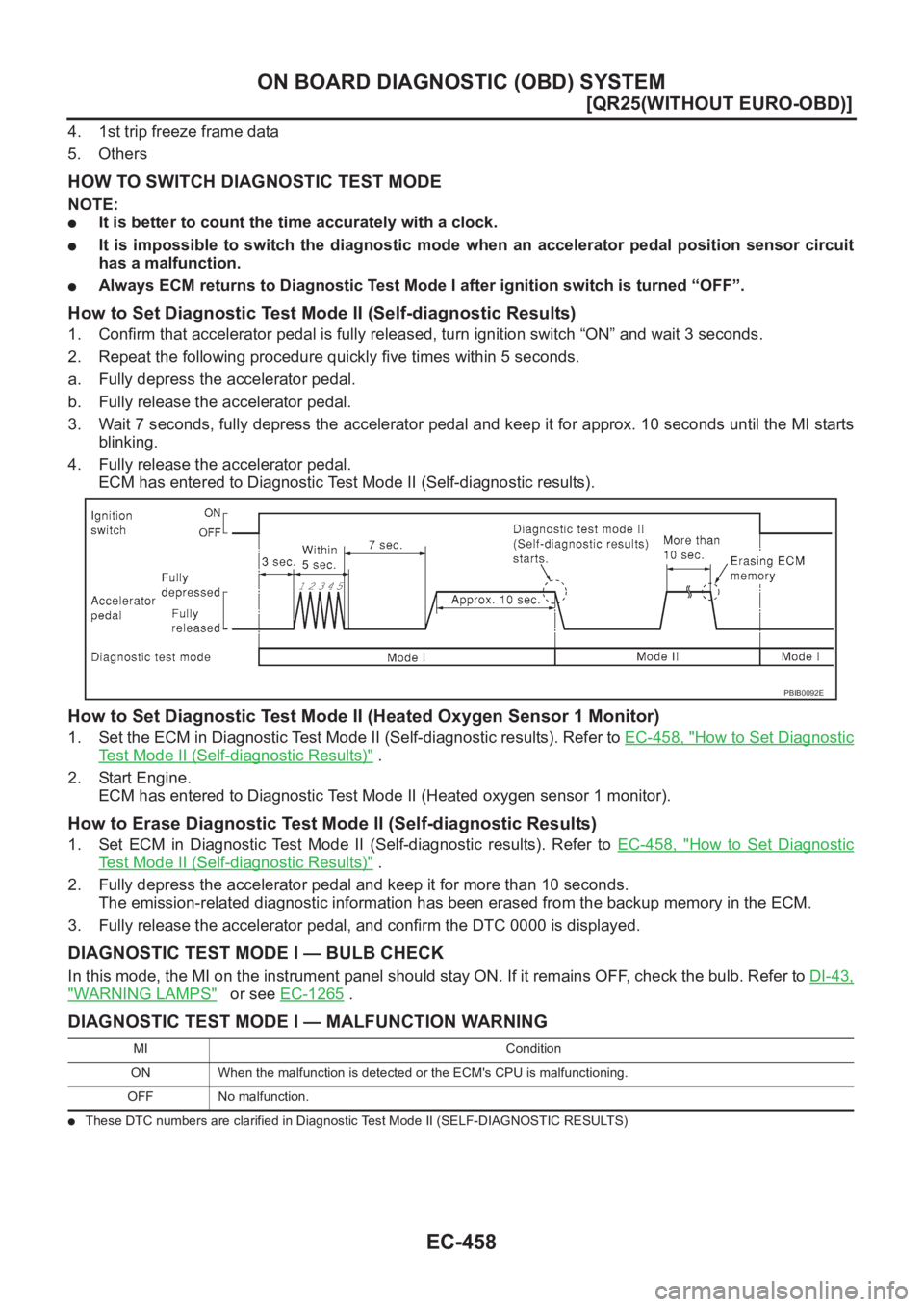
How to Set Diagnostic Test Mode II (Self-diagnostic Results)
1. Confirm that accelerator pedal is fully released, turn ignition switch “ON” and wait 3 seconds.
2. Repeat the following procedure quickly five times within 5 seconds.
a. Fully depress the accelerator pedal.
b. Fully release the accelerator pedal.
3. Wait 7 seconds, fully depress the accelerator pedal and keep it for approx. 10 seconds until the MI starts
blinking.
4. Fully release the accelerator pedal.
ECM has entered to Diagnostic Test Mode II (Self-diagnostic results).
How to Set Diagnostic Test Mode II (Heated Oxygen Sensor 1 Monitor)
1. Set the ECM in Diagnostic Test Mode II (Self-diagnostic results). Refer to EC-458, "How to Set Diagnostic
Test Mode II (Self-diagnostic Results)" .
2. Start Engine.
ECM has entered to Diagnostic Test Mode II (Heated oxygen sensor 1 monitor).
How to Erase Diagnostic Test Mode II (Self-diagnostic Results)
1. Set ECM in Diagnostic Test Mode II (Self-diagnostic results). Refer to EC-458, "How to Set Diagnostic
Test Mode II (Self-diagnostic Results)" .
2. Fully depress the accelerator pedal and keep it for more than 10 seconds.
The emission-related diagnostic information has been erased from the backup memory in the ECM.
3. Fully release the accelerator pedal, and confirm the DTC 0000 is displayed.
DIAGNOSTIC TEST MODE I — BULB CHECK
In this mode, the MI on the instrument panel should stay ON. If it remains OFF, check the bulb. Refer to DI-43,
"WARNING LAMPS" or see EC-1265 .
DIAGNOSTIC TEST MODE I — MALFUNCTION WARNING
●These DTC numbers are clarified in Diagnostic Test Mode II (SELF-DIAGNOSTIC RESULTS)
PBIB0092E
MI Condition
ON When the malfunction is detected or the ECM's CPU is malfunctioning.
OFF No malfunction.
Page 926 of 3833
EC-576
[QR25(WITHOUT EURO-OBD)]
DTC P0650 MI
DTC P0650 MI
PFP:24810
Component DescriptionEBS00NHA
Malfunction Indicator (MI) is located on the instrument panel. When the ignition switch is turned ON without
engine running, MI will light up. This is a bulb check. When the engine is started, MI should go off. If MI
remains on, the on board diagnostic system has detected an engine system malfunction.
On Board Diagnosis LogicEBS00NHB
FAIL-SAFE MODE
ECM enters fail-safe mode when both DTC P0650 and another DTC, which calls for MI to light up, are
detected at the same time.
DTC Confirmation ProcedureEBS00NHC
NOTE:
If “DTC Confirmation Procedure” has been previously conducted, always turn ignition switch “OFF” and wait at
least 10 seconds before conducting the next test.
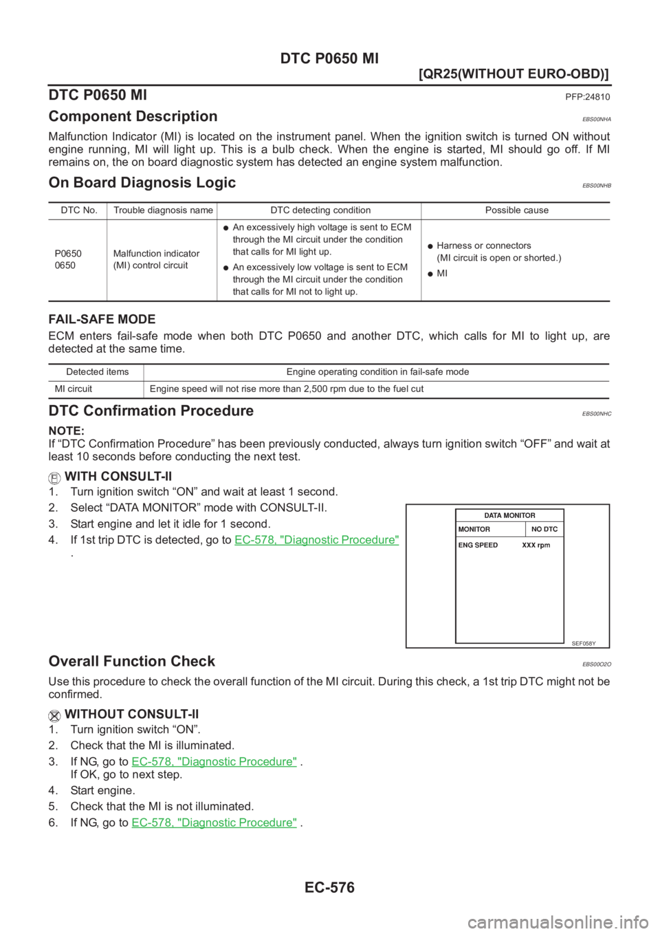
WITH CONSULT-II
1. Turn ignition switch “ON” and wait at least 1 second.
2. Select “DATA MONITOR” mode with CONSULT-II.
3. Start engine and let it idle for 1 second.
4. If 1st trip DTC is detected, go to EC-578, "
Diagnostic Procedure"
.
Overall Function CheckEBS00O2O
Use this procedure to check the overall function of the MI circuit. During this check, a 1st trip DTC might not be
confirmed.
WITHOUT CONSULT-II
1. Turn ignition switch “ON”.
2. Check that the MI is illuminated.
3. If NG, go to EC-578, "
Diagnostic Procedure" .
If OK, go to next step.
4. Start engine.
5. Check that the MI is not illuminated.
6. If NG, go to EC-578, "
Diagnostic Procedure" .
DTC No. Trouble diagnosis name DTC detecting condition Possible cause
P0650
0650Malfunction indicator
(MI) control circuit
●An excessively high voltage is sent to ECM
through the MI circuit under the condition
that calls for MI light up.
●An excessively low voltage is sent to ECM
through the MI circuit under the condition
that calls for MI not to light up.
●Harness or connectors
(MI circuit is open or shorted.)
●MI
Detected items Engine operating condition in fail-safe mode
MI circuit Engine speed will not rise more than 2,500 rpm due to the fuel cut
SEF058Y
Page 1115 of 3833
ENGINE CONTROL SYSTEM
EC-765
[QR20(WITH EURO-OBD)]
C
D
E
F
G
H
I
J
K
L
MA
EC
System ChartEBS00MSA
*1: This sensor is not used to control the engine system under normal conditions.
*2: These signals are sent to the ECM through CAN communication line.
Multiport Fuel Injection (MFI) SystemEBS00MSB
INPUT/OUTPUT SIGNAL CHART
*1: Under normal conditions, this sensor is not for engine control operation.
*2: This signal is sent to the ECM through CAN communication line. Input (Sensor) ECM Function Output (Actuator)
●Camshaft position sensor (PHASE)
●Crankshaft position sensor (POS)
●Mass air flow sensor
●Engine coolant temperature sensor
●Heated oxygen sensor 1
●Throttle position sensor
●Accelerator pedal position sensor
●Park/neutral position (PNP) switch
●Intake air temperature sensor
●Power steering pressure sensor
●Ignition switch
●Battery voltage
●Knock sensor
●Refrigerant pressure sensor
●Heated oxygen sensor 2 *1
●TCM (Transmission control module) *2
●ESP/TCS/ABS control unit *2
●Wheel sensor
●Air conditioner switch
●Electrical loadFuel injection & mixture ratio control Fuel injectors
Electronic ignition system Power transistors
Fuel pump control Fuel pump relay
On board diagnostic system MI (On the instrument panel)
Heated oxygen sensor 1 heater control Heated oxygen sensor 1 heater
Heated oxygen sensor 2 heater control Heated oxygen sensor 2 heater
EVAP canister purge flow controlEVAP canister purge volume control
solenoid valve
Air conditioning cut control Air conditioner relay
Cooling fan control Cooling fan relays
Sensor Input Signal to ECMECM func-
tionActuator
Crankshaft position sensor (POS)
Engine speed
Piston position
Fuel injec-
tion & mix-
ture ratio
controlFuel injectors Camshaft position sensor (PHASE)
Mass air flow sensor Amount of intake air
Engine coolant temperature sensor Engine coolant temperature
Heated oxygen sensor 1 Density of oxygen in exhaust gas
Throttle position sensor Throttle position
Accelerator pedal position sensor Accelerator pedal position
Park/neutral position (PNP) switch Gear position
Ignition switch Start signal
Knock sensor Engine knocking condition
Battery Battery voltage
Power steering pressure sensor Power steering operation
Heated oxygen sensor 2 *1 Density of oxygen in exhaust gas
ESP/TCS/ABS control unit *2 ESP/TCS operation command
Wheel sensor Vehicle speed
Air conditioner switch Air conditioner operation
Page 1127 of 3833
ON BOARD DIAGNOSTIC (OBD) SYSTEM
EC-777
[QR20(WITH EURO-OBD)]
C
D
E
F
G
H
I
J
K
L
MA
EC
ON BOARD DIAGNOSTIC (OBD) SYSTEMPFP:00028
IntroductionEBS00MSL
The ECM has an on board diagnostic system, which detects malfunctions related to engine sensors or actua-
tors. The ECM also records various emission-related diagnostic information including:
The above information can be checked using procedures listed in the table below.
×: Applicable —: Not applicable
*1: 1st trip DTCs for self-diagnoses concerning SRT items cannot be shown on the GST display.
*2: When DTC and 1st trip DTC simultaneously appear on the display, they cannot be clearly distinguished from each other.
The malfunction indicator (MI) on the instrument panel lights up when the same malfunction is detected in two
consecutive trips (Two trip detection logic), or when the ECM enters fail-safe mode. (Refer to EC-753
.)
Two Trip Detection LogicEBS00MSM
When a malfunction is detected for the first time, 1st trip DTC and 1st trip Freeze Frame data are stored in the
ECM memory. The MI will not light up at this stage. <1st trip>
If the same malfunction is detected again during the next drive, the DTC and Freeze Frame data are stored in
the ECM memory, and the MI lights up. The MI lights up at the same time when the DTC is stored. <2nd trip>
The “trip” in the “Two Trip Detection Logic” means a driving mode in which self-diagnosis is performed during
vehicle operation. Specific on board diagnostic items will cause the ECM to light up or blink the MI, and store
DTC and Freeze Frame data, even in the 1st trip, as shown below.
×: Applicable —: Not applicable Emission-related diagnostic information ISO Standard
Diagnostic Trouble Code (DTC) Mode 3 of ISO 15031-5
Freeze Frame data Mode 2 of ISO 15031-5
System Readiness Test (SRT) code Mode 1 of ISO 15031-5
1st Trip Diagnostic Trouble Code (1st Trip DTC) Mode 7 of ISO 15031-5
1st Trip Freeze Frame data
Test values and Test limits Mode 6 of ISO 15031-5
Calibration ID Mode 9 of ISO 15031-5
DTC 1st trip DTCFreeze Frame
data1st trip Freeze
Frame dataSRT code Test value
CONSULT-II×× × × ×—
GST×
×*
1×—××
ECM×
×*
2————
ItemsMI DTC 1st trip DTC
1st trip 2nd trip
1st trip
displaying2nd trip
displaying1st trip
displaying2nd trip
display-
ing BlinkingLighting
upBlinkingLighting
up
Misfire (Possible three way cata-
lyst damage) — DTC: P0300 -
P0304 is being detected×———— —×—
Misfire (Possible three way cata-
lyst damage) — DTC: P0300 -
P0304 is being detected——×——×——
One trip detection diagnoses
(Refer to EC-753
)—×——×—×—
Except above — — —×—××—
Page 1140 of 3833
EC-790
[QR20(WITH EURO-OBD)]
ON BOARD DIAGNOSTIC (OBD) SYSTEM
5. System readiness test (SRT) codes
6. Test values
7. Others
Actual work procedures are explained using a DTC as an example. Be careful so that not only the DTC, but all
of the data listed above, are cleared from the ECM memory during work procedures.
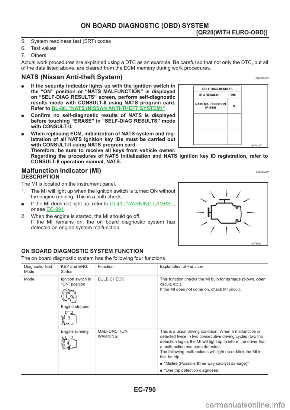
NATS (Nissan Anti-theft System)EBS00MSO
●If the security indicator lights up with the ignition switch in
the “ON” position or “NATS MALFUNCTION” is displayed
on “SELF-DIAG RESULTS” screen, perform self-diagnostic
results mode with CONSULT-II using NATS program card.
Refer to BL-80, "
NATS (NISSAN ANTI-THEFT SYSTEM)" .
●Confirm no self-diagnostic results of NATS is displayed
before touching “ERASE” in “SELF-DIAG RESULTS” mode
with CONSULT-II.
●When replacing ECM, initialization of NATS system and reg-
istration of all NATS ignition key IDs must be carried out
with CONSULT-II using NATS program card.
Therefore, be sure to receive all keys from vehicle owner.
Regarding the procedures of NATS initialization and NATS ignition key ID registration, refer to
CONSULT-II operation manual, NATS.
Malfunction Indicator (MI)EBS00MSP
DESCRIPTION
The MI is located on the instrument panel.
1. The MI will light up when the ignition switch is turned ON without
the engine running. This is a bulb check.
●If the MI does not light up, refer to DI-43, "WARNING LAMPS" ,
or see EC-991
.
2. When the engine is started, the MI should go off.
If the MI remains on, the on board diagnostic system has
detected an engine system malfunction.
ON BOARD DIAGNOSTIC SYSTEM FUNCTION
The on board diagnostic system has the following four functions.
SEF515Y
SAT652J
Diagnostic Test
ModeKEY and ENG.
Sta tusFunction Explanation of Function
Mode I Ignition switch in
“ON” position
Engine stoppedBULB CHECK This function checks the MI bulb for damage (blown, open
circuit, etc.).
If the MI does not come on, check MI circuit.
Engine running MALFUNCTION
WARNINGThis is a usual driving condition. When a malfunction is
detected twice in two consecutive driving cycles (two trip
detection logic), the MI will light up to inform the driver that
a malfunction has been detected.
The following malfunctions will light up or blink the MI in
the 1st trip.
●“Misfire (Possible three way catalyst damage)”
●“One trip detection diagnoses”
Page 1142 of 3833
EC-792
[QR20(WITH EURO-OBD)]
ON BOARD DIAGNOSTIC (OBD) SYSTEM
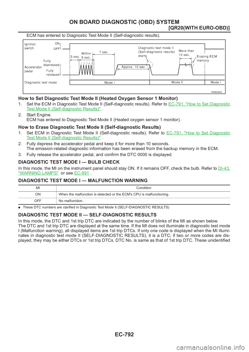
ECM has entered to Diagnostic Test Mode II (Self-diagnostic results).
How to Set Diagnostic Test Mode II (Heated Oxygen Sensor 1 Monitor)
1. Set the ECM in Diagnostic Test Mode II (Self-diagnostic results). Refer to EC-791, "How to Set Diagnostic
Test Mode II (Self-diagnostic Results)" .
2. Start Engine.
ECM has entered to Diagnostic Test Mode II (Heated oxygen sensor 1 monitor).
How to Erase Diagnostic Test Mode II (Self-diagnostic Results)
1. Set ECM in Diagnostic Test Mode II (Self-diagnostic results). Refer to EC-791, "How to Set Diagnostic
Test Mode II (Self-diagnostic Results)" .
2. Fully depress the accelerator pedal and keep it for more than 10 seconds.
The emission-related diagnostic information has been erased from the backup memory in the ECM.
3. Fully release the accelerator pedal, and confirm the DTC 0000 is displayed.
DIAGNOSTIC TEST MODE I — BULB CHECK
In this mode, the MI on the instrument panel should stay ON. If it remains OFF, check the bulb. Refer to DI-43,
"WARNING LAMPS" or see EC-991 .
DIAGNOSTIC TEST MODE I — MALFUNCTION WARNING
●These DTC numbers are clarified in Diagnostic Test Mode II (SELF-DIAGNOSTIC RESULTS)
DIAGNOSTIC TEST MODE II — SELF-DIAGNOSTIC RESULTS
In this mode, the DTC and 1st trip DTC are indicated by the number of blinks of the MI as shown below.
The DTC and 1st trip DTC are displayed at the same time. If the MI does not illuminate in diagnostic test mode
I (Malfunction warning), all displayed items are 1st trip DTCs. If only one code is displayed when the MI illumi-
nates in diagnostic test mode II (SELF-DIAGNOSTIC RESULTS), it is a DTC; if two or more codes are dis-
played, they may be either DTCs or 1st trip DTCs. DTC No. is same as that of 1st trip DTC. These unidentified
PBIB0092E
MI Condition
ON When the malfunction is detected or the ECM's CPU is malfunctioning.
OFF No malfunction.
Page 1341 of 3833
DTC P0650 MI
EC-991
[QR20(WITH EURO-OBD)]
C
D
E
F
G
H
I
J
K
L
MA
EC
DTC P0650 MIPFP:24810
Component DescriptionEBS00MYL
Malfunction Indicator (MI) is located on the instrument panel. When the ignition switch is turned ON without
engine running, MI will light up. This is a bulb check. When the engine is started, MI should go off. If MI
remains on, the on board diagnostic system has detected an engine system malfunction.
On Board Diagnosis LogicEBS00MYM
The MI will not light up for this diagnosis.
FAIL-SAFE MODE
ECM enters fail-safe mode when both DTC P0650 and another DTC, which calls for MI to light up, are
detected at the same time.
DTC Confirmation ProcedureEBS00MYN
NOTE:
If “DTC Confirmation Procedure” has been previously conducted, always turn ignition switch “OFF” and wait at
least 10 seconds before conducting the next test.
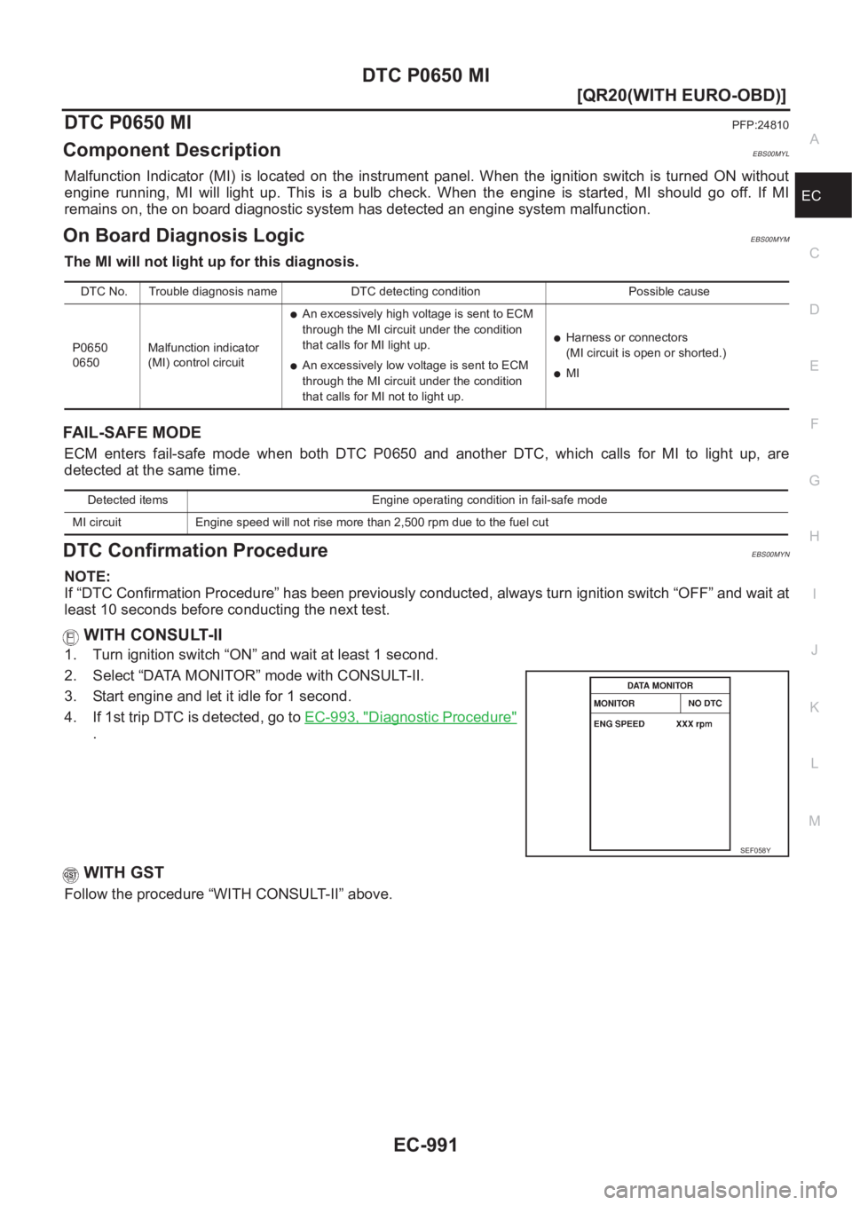
WITH CONSULT-II
1. Turn ignition switch “ON” and wait at least 1 second.
2. Select “DATA MONITOR” mode with CONSULT-II.
3. Start engine and let it idle for 1 second.
4. If 1st trip DTC is detected, go to EC-993, "
Diagnostic Procedure"
.
WITH GST
Follow the procedure “WITH CONSULT-II” above.
DTC No. Trouble diagnosis name DTC detecting condition Possible cause
P0650
0650Malfunction indicator
(MI) control circuit
●An excessively high voltage is sent to ECM
through the MI circuit under the condition
that calls for MI light up.
●An excessively low voltage is sent to ECM
through the MI circuit under the condition
that calls for MI not to light up.
●Harness or connectors
(MI circuit is open or shorted.)
●MI
Detected items Engine operating condition in fail-safe mode
MI circuit Engine speed will not rise more than 2,500 rpm due to the fuel cut
SEF058Y
Page 1479 of 3833
ENGINE CONTROL SYSTEM
EC-1129
[QR20(WITHOUT EURO-OBD)]
C
D
E
F
G
H
I
J
K
L
MA
EC
System ChartEBS00N3G
*1: This sensor is not used to control the engine system under normal conditions.
*2: These signals are sent to the ECM through CAN communication line.
Multiport Fuel Injection (MFI) SystemEBS00N3H
INPUT/OUTPUT SIGNAL CHART
*1: Under normal conditions, this sensor is not for engine control operation.
*2: This signal is sent to the ECM through CAN communication line. Input (Sensor) ECM Function Output (Actuator)
●Camshaft position sensor (PHASE)
●Crankshaft position sensor (POS)
●Mass air flow sensor
●Engine coolant temperature sensor
●Heated oxygen sensor 1
●Throttle position sensor
●Accelerator pedal position sensor
●Park/neutral position (PNP) switch
●Intake air temperature sensor
●Power steering pressure sensor
●Ignition switch
●Battery voltage
●Knock sensor
●Refrigerant pressure sensor
●Heated oxygen sensor 2 *1
●TCM (Transmission control module) *2
●ESP/TCS/ABS control unit *2
●Wheel sensor
●Air conditioner switch
●Electrical loadFuel injection & mixture ratio control Fuel injectors
Electronic ignition system Power transistors
Fuel pump control Fuel pump relay
On board diagnostic system MI (On the instrument panel)
Heated oxygen sensor 1 heater control Heated oxygen sensor 1 heater
Heated oxygen sensor 2 heater control Heated oxygen sensor 2 heater
EVAP canister purge flow controlEVAP canister purge volume control
solenoid valve
Air conditioning cut control Air conditioner relay
Cooling fan control Cooling fan relays
Sensor Input Signal to ECMECM
functionActuator
Crankshaft position sensor (POS)
Engine speed
Piston position
Fuel injec-
tion & mix-
ture ratio
controlFuel injectors Camshaft position sensor (PHASE)
Mass air flow sensor Amount of intake air
Engine coolant temperature sensor Engine coolant temperature
Heated oxygen sensor 1 Density of oxygen in exhaust gas
Throttle position sensor Throttle position
Accelerator pedal position sensor Accelerator pedal position
Park/neutral position (PNP) switch Gear position
Ignition switch Start signal
Knock sensor Engine knocking condition
Battery Battery voltage
Power steering pressure sensor Power steering operation
Heated oxygen sensor 2 *
1Density of oxygen in exhaust gas
ESP/TCS/ABS control unit *
2ESP/TCS operation command
Wheel sensor Vehicle speed
Air conditioner switch Air conditioner operation
Page 1491 of 3833
ON BOARD DIAGNOSTIC (OBD) SYSTEM
EC-1141
[QR20(WITHOUT EURO-OBD)]
C
D
E
F
G
H
I
J
K
L
MA
EC
ON BOARD DIAGNOSTIC (OBD) SYSTEMPFP:00028
IntroductionEBS00N3R
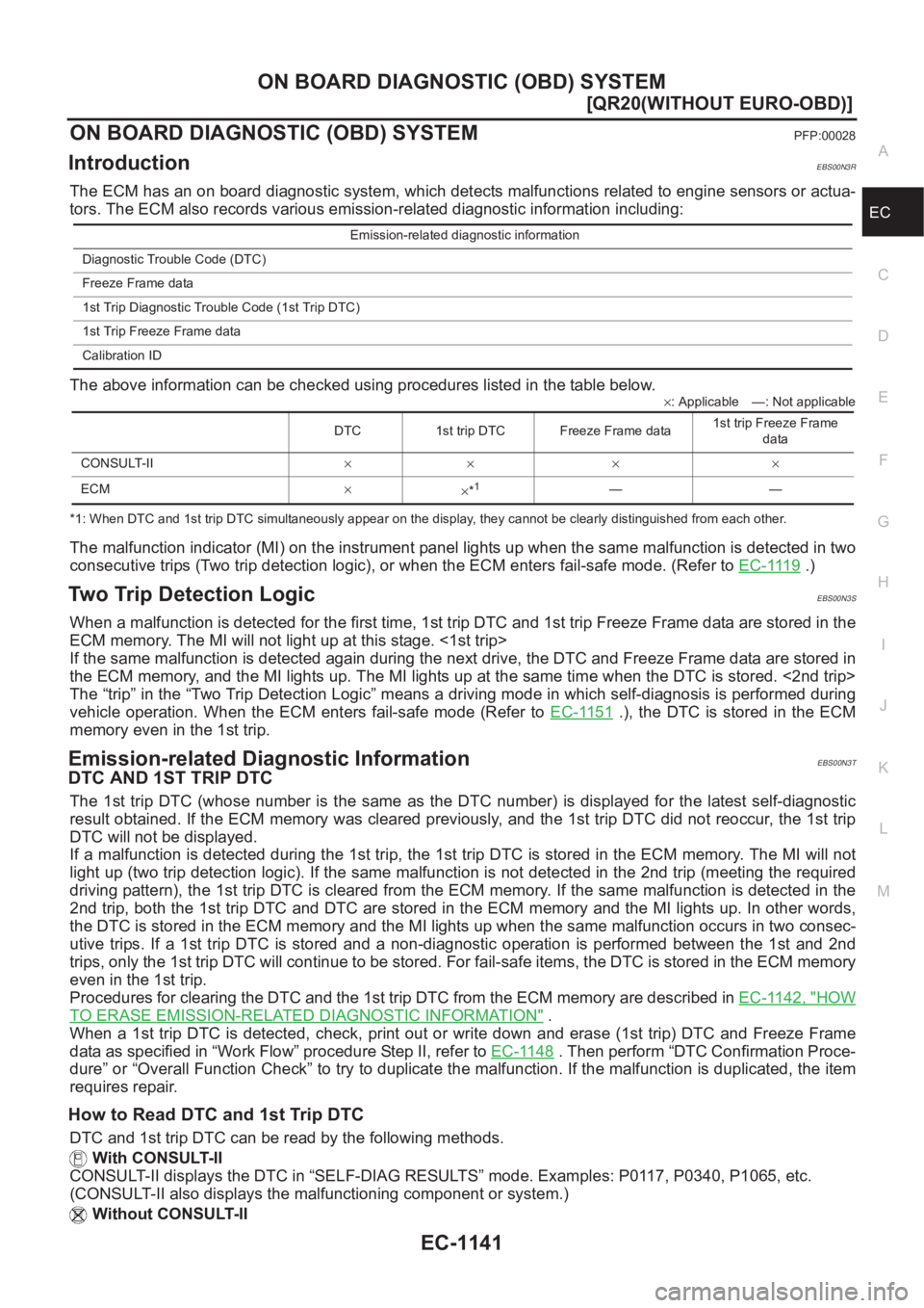
The ECM has an on board diagnostic system, which detects malfunctions related to engine sensors or actua-
tors. The ECM also records various emission-related diagnostic information including:
The above information can be checked using procedures listed in the table below.
×: Applicable —: Not applicable
*1: When DTC and 1st trip DTC simultaneously appear on the display, they cannot be clearly distinguished from each other.
The malfunction indicator (MI) on the instrument panel lights up when the same malfunction is detected in two
consecutive trips (Two trip detection logic), or when the ECM enters fail-safe mode. (Refer to EC-1119
.)
Two Trip Detection LogicEBS00N3S
When a malfunction is detected for the first time, 1st trip DTC and 1st trip Freeze Frame data are stored in the
ECM memory. The MI will not light up at this stage. <1st trip>
If the same malfunction is detected again during the next drive, the DTC and Freeze Frame data are stored in
the ECM memory, and the MI lights up. The MI lights up at the same time when the DTC is stored. <2nd trip>
The “trip” in the “Two Trip Detection Logic” means a driving mode in which self-diagnosis is performed during
vehicle operation. When the ECM enters fail-safe mode (Refer to EC-1151
.), the DTC is stored in the ECM
memory even in the 1st trip.
Emission-related Diagnostic InformationEBS00N3T
DTC AND 1ST TRIP DTC
The 1st trip DTC (whose number is the same as the DTC number) is displayed for the latest self-diagnostic
result obtained. If the ECM memory was cleared previously, and the 1st trip DTC did not reoccur, the 1st trip
DTC will not be displayed.
If a malfunction is detected during the 1st trip, the 1st trip DTC is stored in the ECM memory. The MI will not
light up (two trip detection logic). If the same malfunction is not detected in the 2nd trip (meeting the required
driving pattern), the 1st trip DTC is cleared from the ECM memory. If the same malfunction is detected in the
2nd trip, both the 1st trip DTC and DTC are stored in the ECM memory and the MI lights up. In other words,
the DTC is stored in the ECM memory and the MI lights up when the same malfunction occurs in two consec-
utive trips. If a 1st trip DTC is stored and a non-diagnostic operation is performed between the 1st and 2nd
trips, only the 1st trip DTC will continue to be stored. For fail-safe items, the DTC is stored in the ECM memory
even in the 1st trip.
Procedures for clearing the DTC and the 1st trip DTC from the ECM memory are described in EC-1142, "
HOW
TO ERASE EMISSION-RELATED DIAGNOSTIC INFORMATION" .
When a 1st trip DTC is detected, check, print out or write down and erase (1st trip) DTC and Freeze Frame
data as specified in “Work Flow” procedure Step II, refer to EC-1148
. Then perform “DTC Confirmation Proce-
dure” or “Overall Function Check” to try to duplicate the malfunction. If the malfunction is duplicated, the item
requires repair.
How to Read DTC and 1st Trip DTC
DTC and 1st trip DTC can be read by the following methods.
With CONSULT-II
CONSULT-II displays the DTC in “SELF-DIAG RESULTS” mode. Examples: P0117, P0340, P1065, etc.
(CONSULT-II also displays the malfunctioning component or system.)
Without CONSULT-II
Emission-related diagnostic information
Diagnostic Trouble Code (DTC)
Freeze Frame data
1st Trip Diagnostic Trouble Code (1st Trip DTC)
1st Trip Freeze Frame data
Calibration ID
DTC 1st trip DTC Freeze Frame data1st trip Freeze Frame
data
CONSULT-II×× × ×
ECM×
×*
1——
Page 1494 of 3833
EC-1144
[QR20(WITHOUT EURO-OBD)]
ON BOARD DIAGNOSTIC (OBD) SYSTEM
Malfunction Indicator (MI)
EBS00N3V
DESCRIPTION
The MI is located on the instrument panel.
1. The MI will light up when the ignition switch is turned ON without
the engine running. This is a bulb check.
●If the MI does not light up, refer to DI-43, "WARNING LAMPS" ,
or see EC-1265
.
2. When the engine is started, the MI should go off.
If the MI remains on, the on board diagnostic system has
detected an engine system malfunction.
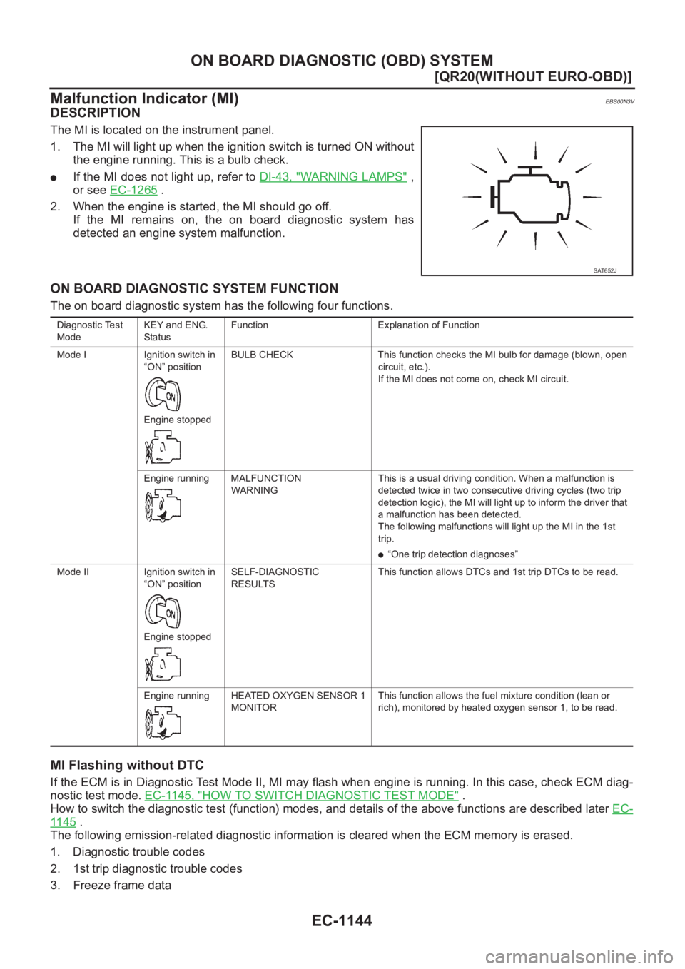
ON BOARD DIAGNOSTIC SYSTEM FUNCTION
The on board diagnostic system has the following four functions.
MI Flashing without DTC
If the ECM is in Diagnostic Test Mode II, MI may flash when engine is running. In this case, check ECM diag-
nostic test mode. EC-1145, "
HOW TO SWITCH DIAGNOSTIC TEST MODE" .
How to switch the diagnostic test (function) modes, and details of the above functions are described later EC-
11 4 5 .
The following emission-related diagnostic information is cleared when the ECM memory is erased.
1. Diagnostic trouble codes
2. 1st trip diagnostic trouble codes
3. Freeze frame data
SAT652J
Diagnostic Test
ModeKEY and ENG.
Sta tusFunction Explanation of Function
Mode I Ignition switch in
“ON” position
Engine stoppedBULB CHECK This function checks the MI bulb for damage (blown, open
circuit, etc.).
If the MI does not come on, check MI circuit.
Engine running MALFUNCTION
WARNINGThis is a usual driving condition. When a malfunction is
detected twice in two consecutive driving cycles (two trip
detection logic), the MI will light up to inform the driver that
a malfunction has been detected.
The following malfunctions will light up the MI in the 1st
trip.
●“One trip detection diagnoses”
Mode II Ignition switch in
“ON” position
Engine stoppedSELF-DIAGNOSTIC
RESULTSThis function allows DTCs and 1st trip DTCs to be read.
Engine running HEATED OXYGEN SENSOR 1
MONITORThis function allows the fuel mixture condition (lean or
rich), monitored by heated oxygen sensor 1, to be read.