tow NISSAN X-TRAIL 2001 Service Owner's Manual
[x] Cancel search | Manufacturer: NISSAN, Model Year: 2001, Model line: X-TRAIL, Model: NISSAN X-TRAIL 2001Pages: 3833, PDF Size: 39.49 MB
Page 2714 of 3833
FSU-8
COIL SPRING AND SHOCK ABSORBER
COIL SPRING AND SHOCK ABSORBER
PFP:54302
Removal and InstallationEES00074
REMOVAL
1. Remove tires. Remove brake caliper and hung it aside.
CAUTION:
Avoid depressing brake pedal with brake caliper removed.
2. Remove electrical wires of ABS wheel speed sensor from strut.
3. Remove brake hose lock plate.
4. Remove mounting bolts and nuts securing steering knuckle to strut.
5. Remove mounting nuts on upper mounting plate and remove upper mounting plate and strut from vehicle.
INSTALLATION
●Refer to FSU-5, "Components" in “Front Suspension Assembly” for tightening torque. Tighten in the
reverse order of removal.
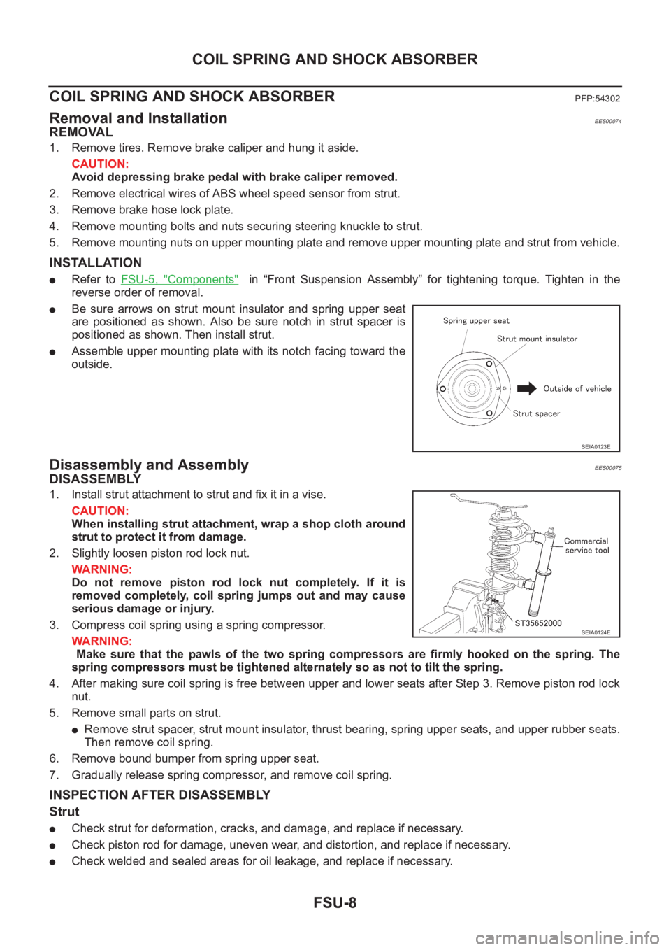
●Be sure arrows on strut mount insulator and spring upper seat
are positioned as shown. Also be sure notch in strut spacer is
positioned as shown. Then install strut.
●Assemble upper mounting plate with its notch facing toward the
outside.
Disassembly and AssemblyEES00075
DISASSEMBLY
1. Install strut attachment to strut and fix it in a vise.
CAUTION:
When installing strut attachment, wrap a shop cloth around
strut to protect it from damage.
2. Slightly loosen piston rod lock nut.
WARNING:
Do not remove piston rod lock nut completely. If it is
removed completely, coil spring jumps out and may cause
serious damage or injury.
3. Compress coil spring using a spring compressor.
WARNING:
Make sure that the pawls of the two spring compressors are firmly hooked on the spring. The
spring compressors must be tightened alternately so as not to tilt the spring.
4. After making sure coil spring is free between upper and lower seats after Step 3. Remove piston rod lock
nut.
5. Remove small parts on strut.
●Remove strut spacer, strut mount insulator, thrust bearing, spring upper seats, and upper rubber seats.
Then remove coil spring.
6. Remove bound bumper from spring upper seat.
7. Gradually release spring compressor, and remove coil spring.
INSPECTION AFTER DISASSEMBLY
Strut
●Check strut for deformation, cracks, and damage, and replace if necessary.
●Check piston rod for damage, uneven wear, and distortion, and replace if necessary.
●Check welded and sealed areas for oil leakage, and replace if necessary.
SEIA0123E
SEIA0124E
Page 2747 of 3833
BRAKE PEDAL
BR-7
C
D
E
G
H
I
J
K
L
MA
B
BR
ComponentsEFS001CI
Removal and InstallationEFS000C2
REMOVAL
Be careful not to deform brake tube.
1. Remove the instrument lower drive panel.
2. Remove stop lamp switch from brake pedal assembly.
3. Remove snap pin and clevis pin from brake booster clevis.
4. Remove brake pedal assembly mounting nuts. Pull brake booster toward the engine compartment. Be
careful not to deform the brake tube.
5. Remove brake booster clevis from input rod.
6. Remove steering column assembly from steering member.
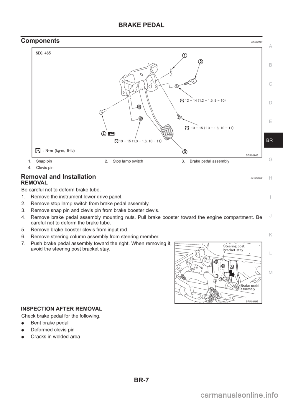
7. Push brake pedal assembly toward the right. When removing it,
avoid the steering post bracket stay.
INSPECTION AFTER REMOVAL
Check brake pedal for the following.
●Bent brake pedal
●Deformed clevis pin
●Cracks in welded area
1. Snap pin 2. Stop lamp switch 3. Brake pedal assembly
4. Clevis pin
SFIA0044E
SFIA0349E
Page 2912 of 3833
PS-2
PRECAUTIONS
PRECAUTIONS
PFP:00001
Precautions for Supplemental Restraint System (SRS) “AIR BAG” and “SEAT
BELT PRE-TENSIONER”
EGS000IZ
The Supplemental Restraint System such as “AIR BAG” and “SEAT BELT PRE-TENSIONER”, used along
with a front seat belt, helps to reduce the risk or severity of injury to the driver and front passenger for certain
types of collision. Information necessary to service the system safely is included in the SRS and SB section of
this Service Manual.
WARNING:
●To avoid rendering the SRS inoperative, which could increase the risk of personal injury or death
in the event of a collision which would result in air bag inflation, all maintenance must be per-
formed by an authorized NISSAN/INFINITI dealer.
●Improper maintenance, including incorrect removal and installation of the SRS, can lead to per-
sonal injury caused by unintentional activation of the system. For removal of Spiral Cable and Air
Bag Module, see the SRS section.
●Do not use electrical test equipment on any circuit related to the SRS unless instructed to in this
Service Manual. SRS wiring harnesses can be identified by yellow and/or orange harness connec-
tors.
CautionEGS00049
●Always follow the warnings and the cautions below in disassembly procedures:
–Work in a clean, dust-free place. No dust proof device is necessary.
–Clean outside of unit before disassembly.
–Clean parts to be disassembled. Be careful not to allow any dirt or other foreign materials to enter or con-
tact with parts.
–Assemble disassembled parts properly, following order shown in manual. If work has been suspended in
the middle of assembly, place a clean cover over parts. This will prevent them from being contaminated.
–Use paper towels when removing dirt and other foreign materials. Cloth shop towels can leave lint on
cleaned parts that might affect operation of parts.
–Clean disassembled parts (except rubber parts) with kerosene. Drain oil by blowing with air or absorbing
with shop papers.
–Before assembling, apply Nissan power steering fluid to O-rings and seals.
–Replace gaskets and O-rings with new ones. Be careful not to damage any O-rings, oil seals, and gaskets
during assembly.
●If following part is scratched after disassembly of steering pump, replace applicable part: case, rear body,
side plate, pulley, rotor, vane, or flow control valve
●Mark source of fluid leak with a white marker for identification.
● Seals and copper washers must not be reused.
Page 2922 of 3833
PS-12
POWER STEERING GEAR AND LINKAGE
POWER STEERING GEAR AND LINKAGE
PFP:49001
Removal and InstallationEGS0004I
REMOVAL
1. Remove cotter pin, and loosen mounting nut. Remove tie rod from steering knuckle with a pitman arm
puller.
CAUTION:
●Be careful not to damage dust boot at ball joint of tie rod.
●Before using pitman arm puller (multi-purpose tool), loosely tighten nut for temporary holding.
2. Mark lower joint and steering gear with paint for easy installation. Remove pinch bolt from gear side of
lower joint.
3. Remove high pressure-side tube and low pressure-side hose of hydraulic piping from steering gear.
4. Remove mounting nuts on upper portion of stabilizer connecting rod and stabilizer clamp mounting bolts.
Move stabilizer toward vehicle front.
5. Remove steering gear assembly mounting bolts and nuts. Remove power steering tube bracket and
steering gear assembly from suspension member.
6. Tilt steering gear to prevent any contact with other parts. Then remove it from right side of vehicle.
INSTALLATION
Paying attention to following items, install in the reverse order of removal.
●After installation, bleed air. Refer to PS-5, "Bleeding Hydraulic System" .
●Remove mounting bolt and nut from upper portion of lower joint. This will facilitate installation of lower joint
to steering gear. Then slide lower joint in place.
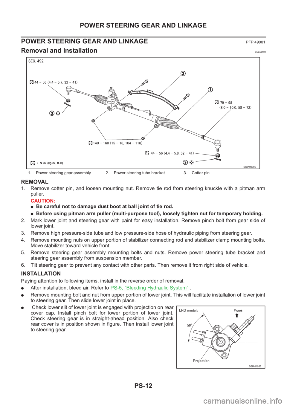
● Check lower slit of lower joint is engaged with projection on rear
cover cap. Install pinch bolt for lower portion of lower joint.
Check steering gear is in straight-ahead position. Also check
rear cover is in position shown in figure. Then install lower joint
to steering gear.
1. Power steering gear assembly 2. Power steering tube bracket 3. Cotter pin
SGIA0009E
SGIA0105E
Page 2941 of 3833
POWER STEERING OIL PUMP
PS-31
C
D
E
F
H
I
J
K
L
MA
B
PS
DISASSEMBLY
CAUTION:
●Parts which can be disassembled are strictly limited. Never disassemble parts other than those
specified.
●Disassemble in as clean a place as possible.
●Clean your hands before disassembly.
●Do not use rags; use nylon cloths or paper towels.
●Follow the procedure and cautions in the Service Manual.
●When disassembling and reassembling, do not let foreign matter enter or contact the parts.
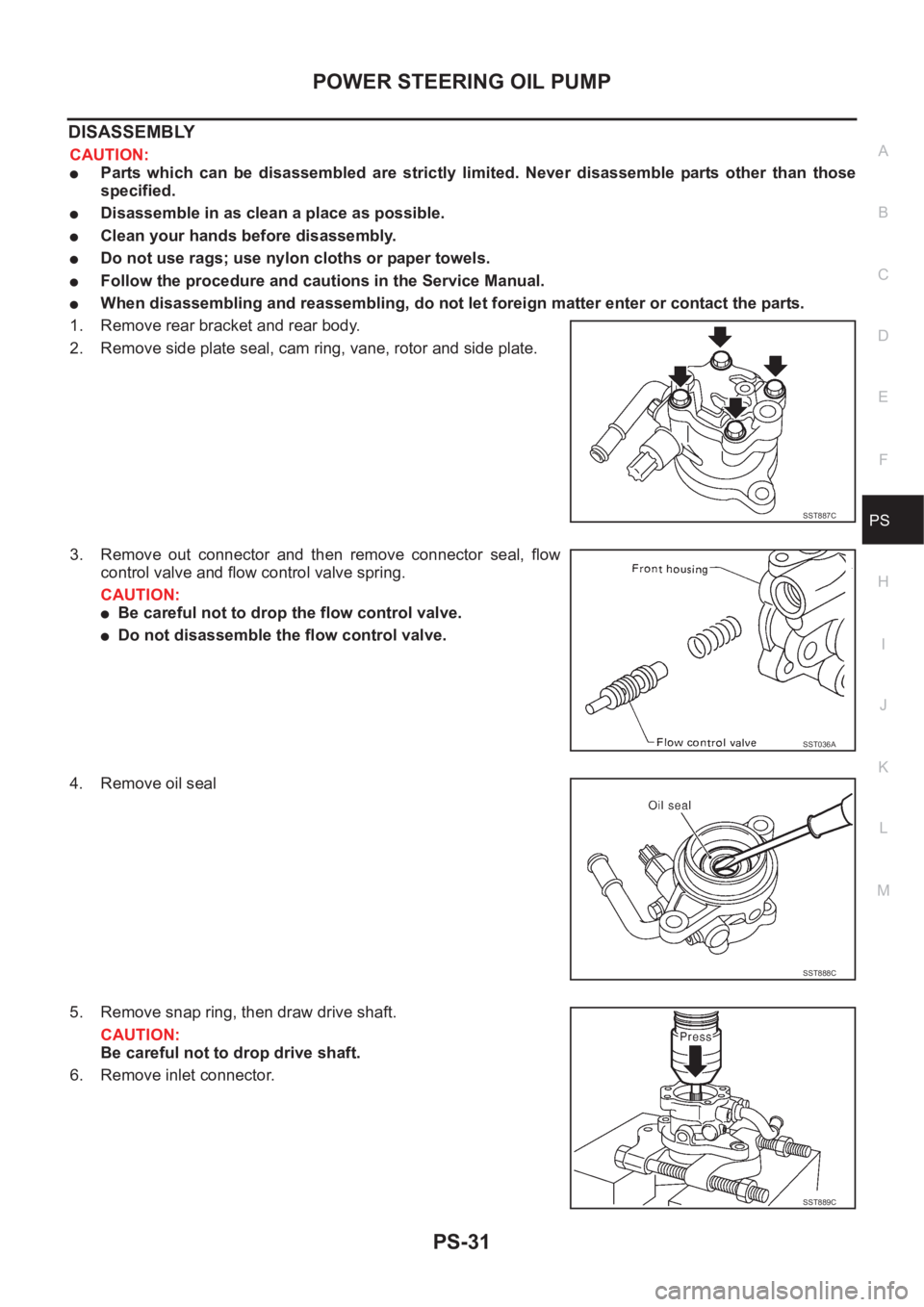
1. Remove rear bracket and rear body.
2. Remove side plate seal, cam ring, vane, rotor and side plate.
3. Remove out connector and then remove connector seal, flow
control valve and flow control valve spring.
CAUTION:
●Be careful not to drop the flow control valve.
●Do not disassemble the flow control valve.
4. Remove oil seal
5. Remove snap ring, then draw drive shaft.
CAUTION:
Be careful not to drop drive shaft.
6. Remove inlet connector.
SST887C
SST036A
SST888C
SST889C
Page 3005 of 3833
PRECAUTIONS
SRS-3
C
D
E
F
G
I
J
K
L
MA
B
SRS
PRECAUTIONSPFP:00001
Precautions for Supplemental Restraint System (SRS) “AIR BAG” and “SEAT
BELT PRE-TENSIONER”
EHS000QI
The Supplemental Restraint System such as “AIR BAG” and “SEAT BELT PRE-TENSIONER”, used along
with a front seat belt, helps to reduce the risk or severity of injury to the driver and front passenger for certain
types of collision. Information necessary to service the system safely is included in the SRS and SB section of
this Service Manual.
WARNING:
●To avoid rendering the SRS inoperative, which could increase the risk of personal injury or death
in the event of a collision which would result in air bag inflation, all maintenance must be per-
formed by an authorized NISSAN/INFINITI dealer.
●Improper maintenance, including incorrect removal and installation of the SRS, can lead to per-
sonal injury caused by unintentional activation of the system. For removal of Spiral Cable and Air
Bag Module, see the SRS section.
●Do not use electrical test equipment on any circuit related to the SRS unless instructed to in this
Service Manual. SRS wiring harnesses can be identified by yellow and/or orange harness connec-
tors.
Precautions for SRS “AIR BAG” and “SEAT BELT PRE-TENSIONER” ServiceEHS000BH
●Do not use electrical test equipment to check SRS circuits unless instructed to in this Service Manual.
●Before servicing the SRS, turn ignition switch “OFF”, disconnect both battery cables and wait at least 3
minutes.
For approximately 3 minutes after the cables is removed, it is still possible for the air bag and seat belt
pre-tensioner to deploy. Therefore, do not work on any SRS connectors or wires until at least 3 minutes
have passed.
●Diagnosis sensor unit must always be installed with their arrow marks “⇐” pointing towards the front of the
vehicle for proper operation. Also check diagnosis sensor unit for cracks, deformities or rust before instal-
lation and replace as required.
●The spiral cable must be aligned with the neutral position since its rotations are limited. Do not attempt to
turn steering wheel or column after removal of steering gear.
●Handle air bag module carefully. Always place driver and front passenger air bag modules with the pad
side facing upward and place front side air bag module standing with stud bolt side setting bottom.
●Conduct self-diagnosis to check entire SRS for proper function after replacing any components.
●After air bag inflates, the front instrument panel assembly should be replaced if damaged.
Trouble Diagnosis PrecautionEHS000BI
When you read wiring diagrams, refer to the followings:
●“HOW TO READ WIRING DIAGRAMS” in GI section
●PG-2, "POWER SUPPLY ROUTING" in PG section
When you perform trouble diagnosis, refer to the followings:
●“HOW TO FOLLOW TEST GROUP IN TROUBLE DIAGNOSIS” in GI section
●“HOW TO PERFORM EFFICIENT DIAGNOSIS FOR AN ELECTRICAL INCIDENT” in GI section
Check for any service bulletins before servicing the vehicle.
Page 3058 of 3833
BL-6
HOOD
Install in the reverse order of removal.
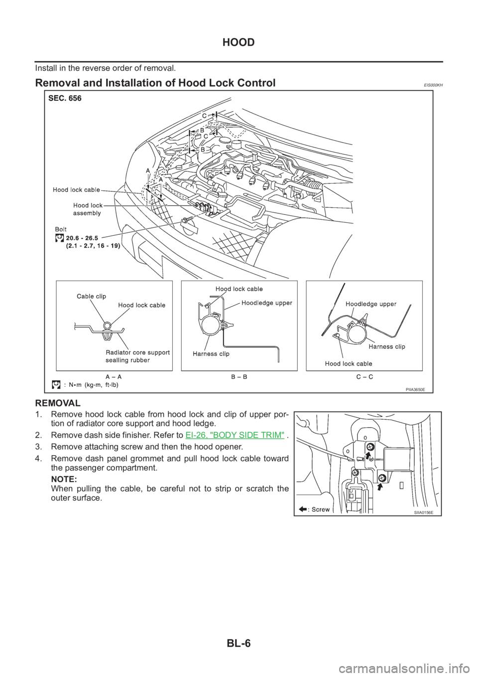
Removal and Installation of Hood Lock ControlEIS000KH
REMOVAL
1. Remove hood lock cable from hood lock and clip of upper por-
tion of radiator core support and hood ledge.
2. Remove dash side finisher. Refer to EI-26, "
BODY SIDE TRIM" .
3. Remove attaching screw and then the hood opener.
4. Remove dash panel grommet and pull hood lock cable toward
the passenger compartment.
NOTE:
When pulling the cable, be careful not to strip or scratch the
outer surface.
PIIA3650E
SIIA0156E
Page 3119 of 3833
FRONT DOOR LOCK
BL-67
C
D
E
F
G
H
J
K
L
MA
B
BL
Disassembly and AssemblyEIS000KY
DISASSEMBLY
NOTE:
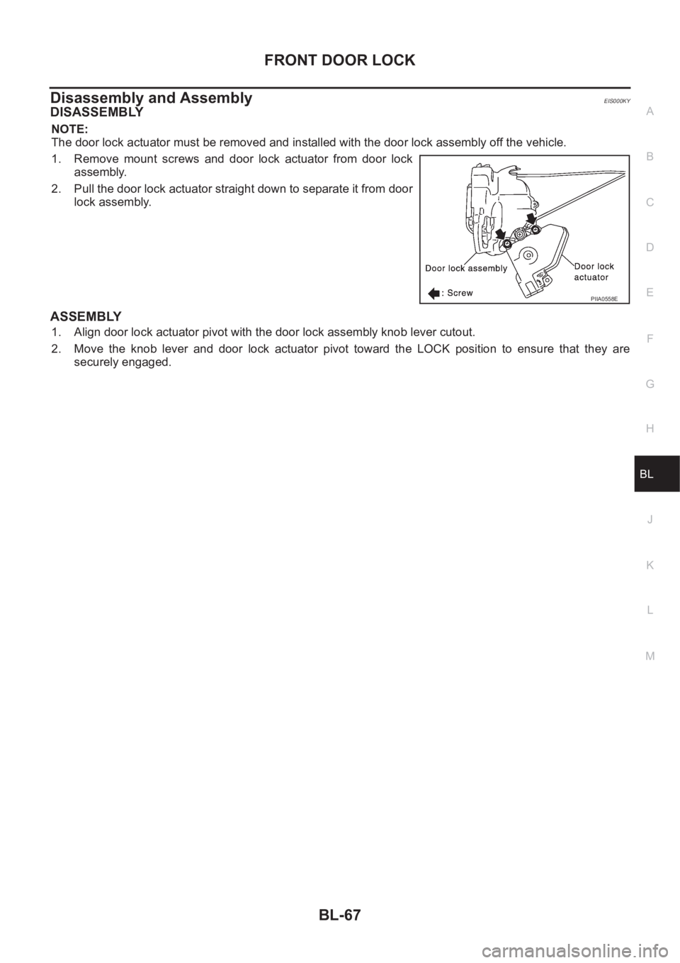
The door lock actuator must be removed and installed with the door lock assembly off the vehicle.
1. Remove mount screws and door lock actuator from door lock
assembly.
2. Pull the door lock actuator straight down to separate it from door
lock assembly.
ASSEMBLY
1. Align door lock actuator pivot with the door lock assembly knob lever cutout.
2. Move the knob lever and door lock actuator pivot toward the LOCK position to ensure that they are
securely engaged.
PIIA0558E
Page 3122 of 3833
BL-70
REAR DOOR LOCK
Disassembly and Assembly
EIS000L2
DISASSEMBLY
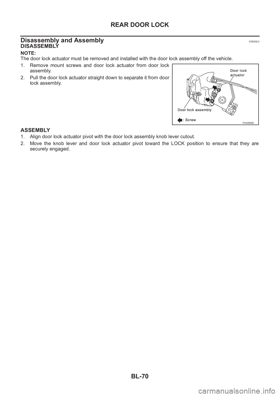
NOTE:
The door lock actuator must be removed and installed with the door lock assembly off the vehicle.
1. Remove mount screws and door lock actuator from door lock
assembly.
2. Pull the door lock actuator straight down to separate it from door
lock assembly.
ASSEMBLY
1. Align door lock actuator pivot with the door lock assembly knob lever cutout.
2. Move the knob lever and door lock actuator pivot toward the LOCK position to ensure that they are
securely engaged.
PIIA0560E
Page 3196 of 3833
GW-44
FRONT DOOR GLASS AND REGULATOR
FRONT DOOR GLASS AND REGULATOR
PFP:80300
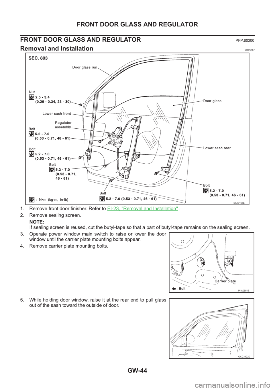
Removal and InstallationEIS00467
1. Remove front door finisher. Refer to EI-23, "Removal and Installation" .
2. Remove sealing screen.
NOTE:
If sealing screen is reused, cut the butyl-tape so that a part of butyl-tape remains on the sealing screen.
3. Operate power window main switch to raise or lower the door
window until the carrier plate mounting bolts appear.
4. Remove carrier plate mounting bolts.
5. While holding door window, raise it at the rear end to pull glass
out of the sash toward the outside of door.
SIIA0165E
PIIA0551E
OCC3422D