length NISSAN X-TRAIL 2001 Service Owner's Guide
[x] Cancel search | Manufacturer: NISSAN, Model Year: 2001, Model line: X-TRAIL, Model: NISSAN X-TRAIL 2001Pages: 3833, PDF Size: 39.49 MB
Page 1934 of 3833

FL-10
[QR]
FUEL TANK
7. Remove exhaust center tube and insulator. Refer to EX-2, "EXHAUST SYSTEM" .
8. Remove propeller shaft. Refer to PR-2, "
REAR PROPELLER SHAFT" .
9. Using a transmission jack, support the bottom of the rear final
drive.
10. Remove the mounting nuts on the rear suspension member, and
lower the transmission jack carefully until just before the rear
suspension member is removed from the stud bolts on the vehi-
cle.
11. Disconnect fuel filler hose, EVAP hose and vent hose at fuel
tank side.
12. For disconnection procedure of the quick connector on the
evaporator hose, Refer to FL-4, "
FUEL LEVEL SENSOR UNIT,
FUEL FILTER AND FUEL PUMP ASSEMBLY" .
13. Remove fuel tank protector.
14. Remove fuel tank band mounting bolts while supporting fuel
tank.
15. Remove fuel tank.
INSTALLATION
Install in the reverse order of removal paying attention to the following.
●Surely clamp fuel hoses and insert hose to the length below.
●Be sure hose clamp is not placed on swelled area of fuel tube.
●Tighten fuel hose clamp so that the distance between its lugs becomes to the following.
●Push the mounting band pin to the vehicle side securely.
●Before fixing the fuel tank, temporarily install the filler tube.
CAUTION:
Use genuine fuel filler tube mounting bolts or equivalent. Make sure to tighten them to the speci-
fied torque.
●To connect the quick connector, refer to FL-4, "FUEL LEVEL SENSOR UNIT, FUEL FILTER AND FUEL
PUMP ASSEMBLY" .
KBIA0285E
KBIA0286E
KBIA0290E
Fuel filler hose : 35mm (1.38 in)
The other hoses : 25mm (0.98 in)
Fuel tank side : 5 - 9 mm (0.20 - 0.35 in)
Fuel filler tube side : 7 - 11 mm (0.28 - 0.43 in)
Page 1946 of 3833

FL-22
[YD22DDTi]
FUEL TANK
10. Using a transmission jack, support the bottom of the rear final
drive.
11. Remove the mounting nuts on the rear suspension member, and
lower the transmission jack carefully until just before the rear
suspension member is removed from the stud bolts on the vehi-
cle.
12. Disconnect fuel filler hose, EVAP hose and vent hose at fuel
tank side.
For disconnection procedure of the quick connector. Refer to
FL-17, "
FUEL LEVEL SENSOR UNIT" .
13. Remove fuel tank protector.
14. Remove fuel tank band mounting bolts while supporting fuel
tank.
15. Remove fuel tank.
INSTALLATION
●Install in the reverse order of removal paying attention to the following.
●Surely clamp fuel hoses and insert hose to the length below.
●Be sure hose clamp is not positioned on swelled area of fuel tube.
●Tighten fuel hose clamp so that the distance between its lugs becomes to the following.
●Push the mounting band pin to the vehicle side securely.
●Before fixing the fuel tank, temporarily install the fuel filler tube.
CAUTION:
Use genuine fuel filler tube mounting bolts or equivalent. Make sure to tighten them to the speci-
fied torque.
●To connect the quick connector. Refer to FL-17, "FUEL LEVEL SENSOR UNIT" .
INSPECTION AFTER INSTALLATION
Make sure there is no fuel leakage at connections in the following steps.
KBIA0285E
KBIA0286E
KBIA0290E
Fuel filler hose : 35 mm (1.38 in)
The other hose : 25 mm (0.98 in)
Fuel tank side : 5 - 9 mm (0.20 - 0.35 in)
Fuel filler tube side : 7 - 11 mm (0.28 - 0.43 in)
Page 2076 of 3833
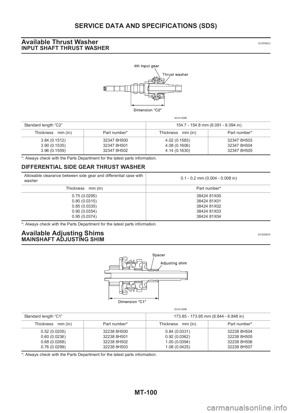
MT-100
SERVICE DATA AND SPECIFICATIONS (SDS)
Available Thrust Washer
ECS008CJ
INPUT SHAFT THRUST WASHER
*: Always check with the Parts Department for the latest parts information.
DIFFERENTIAL SIDE GEAR THRUST WASHER
*: Always check with the Parts Department for the latest parts information.
Available Adjusting ShimsECS008CK
MAINSHAFT ADJUSTING SHIM
*: Always check with the Parts Department for the latest parts information. Standard length “C2” 154.7 - 154.8 mm (6.091 - 6.094 in)
Thickness mm (in) Part number* Thickness mm (in) Part number*
3.84 (0.1512)
3.90 (0.1535)
3.96 (0.1559)32347 8H500
32347 8H501
32347 8H5024.02 (0.1583)
4.08 (0.1606)
4.14 (0.1630)32347 8H503
32347 8H504
32347 8H505
SCIA1008E
Allowable clearance between side gear and differential case with
washer0.1 - 0.2 mm (0.004 - 0.008 in)
Thickness mm (in) Part number*
0.75 (0.0295)
0.80 (0.0315)
0.85 (0.0335)
0.90 (0.0354)
0.95 (0.0374)38424 81X00
38424 81X01
38424 81X02
38424 81X03
38424 81X04
Standard length “C1” 173.85 - 173.95 mm (6.844 - 6.848 in)
Thickness mm (in) Part number* Thickness mm (in) Part number*
0.52 (0.0205)
0.60 (0.0236)
0.68 (0.0268)
0.76 (0.0299)32238 8H500
32238 8H501
32238 8H502
32238 8H5030.84 (0.0331)
0.92 (0.0362)
1.00 (0.0394)
1.08 (0.0425)32238 8H504
32238 8H505
32238 8H506
32238 8H507
SCIA1009E
Page 2493 of 3833

ON-VEHICLE SERVICE
AT-415
[ALL]
D
E
F
G
H
I
J
K
L
MA
B
AT
6. Remove control valve assembly by removing fixing bolts.
Bolt length, number and location:
●Be careful not to drop manual valve and servo release accumulator return springs.
7. Disassemble and inspect control valve assembly if necessary. Refer to AT- 4 1 4 , "
Control Valve Assembly
and Accumulators" .
8. Remove servo release and N-D accumulators by applying com-
pressed air if necessary.
●Hold each piston with a rag.
INSTALLATION
●Tighten fixing bolts to specification.
●Set manual shaft in Neutral position, then align manual
plate with groove in manual valve.
●After installing control valve assembly to transmission
case, make sure that selector lever can be moved to all
positions.
AAT260A
Bolt symbol A B C
Bolt length “ ” mm(in)40.0 mm
(1.575 in)33.0 mm
(1.299 in)43.5 mm
(1.713 in)
Number of bolts 5 6 2
SAT935J
: 7 - 9 N-m (0.7 - 0.9 kg-m, 61 - 78 in-lb)
SAT497H
Page 2498 of 3833

AT-420
[ALL]
REMOVAL AND INSTALLATION
3. Tighten belts fixing transaxle.
4. Reinstall any part removed.
5. Adjust control cable. Refer to AT- 4 1 6 , "
Control Cable Adjust-
ment" .
6. Check continuity of PNP switch. Refer to AT- 11 0 , "
DTC P0705
PARK/NEUTRAL POSITION (PNP) SWITCH" .
7. Refill transaxle with ATF and check fluid level.
8. Move selector lever through all positions to be sure that tran-
saxle operates correctly. With parking brake applied, idle
engine. Move selector lever through “N” to “D”, to “2”, to “1” and
“R” positions. A slight shock should be felt through the hand
gripping the selector each time the transaxle is shifted.
9. Perform road test. Refer to AT-68, "
Road Test" .
Bolt No.Tightening torque
N·m (kg-m, ft-lb)Bolt length “ L ”
mm (in)
1
69.6 - 79.4 (7.1 - 8.1, 51.4 - 58.6)49 (1.93)
2 45 (1.77)
3
39.2 - 46.1 (4.0 - 4.7, 29.0 - 34.0)40 (1.57)
4 30 (1.18)
5
30.4 - 40.2 (3.1 - 4.1, 22.4 - 29.7)40 (1.57)
6 45 (1.97)
SCIA0795E
SAT638A
Page 2507 of 3833

DISASSEMBLY
AT-429
[ALL]
D
E
F
G
H
I
J
K
L
MA
B
AT
16. Check accumulator pistons and contact surface of transmission
case for damage.
17. Check accumulator return springs for damage and free length.
18. Remove lip seals.
19. Remove L & R oil tube and oil sleeve.
20. Remove converter housing according to the following proce-
dures.
a. Remove converter housing mounting bolts.
b. Remove converter housing by tapping it lightly.
c. Remove O-ring from differential oil port.
SAT023DA
SAT006F
SAT862HA
SAT008F
SAT235F
Page 2527 of 3833

REPAIR FOR COMPONENT PARTS
AT-449
[ALL]
D
E
F
G
H
I
J
K
L
MA
B
AT
DISASSEMBLY
Disassemble upper, inter and lower bodies.
Bolt length, number and location:
f: Reamer bolt and nut.
1. Remove bolts a , d and nut f and remove oil strainer from con-
trol valve assembly.
2. Remove solenoid valve assembly and line pressure solenoid
valve from control valve assembly.
Bolt symbolabcde f g
Bolt length “ ” mm (in)
13.5
(0.531)58.0
(2.283)40.0
(1.575)66.0
(2.598)33.0
(1.299)78.0
(3.071)18.0
(0.709)
Number of bolts 6 3 6 11 2 2 1
SAT704J
AAT780
SAT062F
Page 2530 of 3833

AT-452
[ALL]
REPAIR FOR COMPONENT PARTS
●Check to see that retainer plates are properly positioned in
upper body.
●Be careful not to lose these parts.
Oil Strainer
●Check wire netting of oil strainer for damage.
Shift Solenoid Valves “A” and “B”, Line Pressure Solenoid Valve, Torque Converter Clutch
Solenoid Valve and Overrun Clutch Solenoid Valve
●Measure resistance.
●Except for EURO-OBD:
●For shift solenoid valve A, refer to AT- 3 6 7 , "SHIFT SOLENOID
VALVE A" .
●For shift solenoid valve B, refer to AT- 3 7 2 , "SHIFT SOLENOID
VALVE B" .
●For line pressure solenoid valve, refer to AT- 3 9 6 , "LINE PRES-
SURE SOLENOID VALVE" .
●For torque converter clutch solenoid valve, refer to AT- 3 8 1 ,
"TORQUE CONVERTER CLUTCH SOLENOID VALVE" .
●For overrun clutch solenoid valve, refer to AT- 3 7 7 , "OVERRUN
CLUTCH SOLENOID VALVE" .
●EURO-OBD:
●For shift solenoid valve A, refer to AT- 1 7 0 , "DTC P0750 SHIFT SOLENOID VALVE A" .
●For shift solenoid valve B, refer to AT- 1 7 5 , "DTC P0755 SHIFT SOLENOID VALVE B" .
●For line pressure solenoid valve, refer to AT- 1 6 3 , "DTC P0745 LINE PRESSURE SOLENOID VALVE" .
●For torque converter clutch solenoid valve, refer to AT- 1 5 8 , "DTC P0740 TORQUE CONVERTER
CLUTCH SOLENOID VALVE" .
●For overrun clutch solenoid valve, refer to AT- 1 8 5 , "DTC P1760 OVERRUN CLUTCH SOLENOID VALVE"
.
Oil Cooler Relief Valve Spring
●Check springs for damage or deformation.
●Measure free length and outer diameter.
SAT551G
SCIA0805E
Inspection standard: Refer to AT- 5 2 1 , "SERVICE DATA
AND SPECIFICATIONS (SDS)" .
SAT138D
Page 2533 of 3833

REPAIR FOR COMPONENT PARTS
AT-455
[ALL]
D
E
F
G
H
I
J
K
L
MA
B
AT
k. Install lower body on inter body using reamer bolts f as guides
and tighten reamer bolts f slightly.
2. Install O-rings to solenoid valves and terminal body.
●Apply ATF to O-rings.
3. Install and tighten bolts.
Bolt length, number and location:
SAT126DA
SCIA0804E
Bolt symbolabcde f g
Bolt length “ ” mm (in)
13.5
(0.531)58.0
(2.283)40.0
(1.575)66.0
(2.598)33.0
(1.299)78.0
(3.071)18.0
(0.709)
Number of bolts 6 3 6 11 2 2 1
SAT704J
Page 2537 of 3833

REPAIR FOR COMPONENT PARTS
AT-459
[ALL]
D
E
F
G
H
I
J
K
L
MA
B
AT
INSPECTION
Valve Spring
●Measure free length and outer diameter of each valve spring.
Also check for damage or deformation.
●Replace valve springs if deformed or fatigued.
Control Valves
●Check sliding surfaces of valves, sleeves and plugs.
ASSEMBLY
●Lay control valve body down when installing valves. Do not
stand the control valve body upright.
1. Lubricate the control valve body and all valves with ATF. Install
control valves by sliding them carefully into their bores.
●Be careful not to scratch or damage valve body.
●Wrap a small screwdriver with vinyl tape and use it to insert
the valves into their proper positions.Inspection standard :Refer to AT-521, "
SERVICE
DATA AND SPECIFICATIONS
(SDS)" .
SAT138D
SAT139D
SAT140DA
SAT141D