length NISSAN X-TRAIL 2001 Service Workshop Manual
[x] Cancel search | Manufacturer: NISSAN, Model Year: 2001, Model line: X-TRAIL, Model: NISSAN X-TRAIL 2001Pages: 3833, PDF Size: 39.49 MB
Page 2675 of 3833
SERVICE DATA AND SPECIFICATIONS (SDS)
PR-5
C
E
F
G
H
I
J
K
L
MA
B
PR
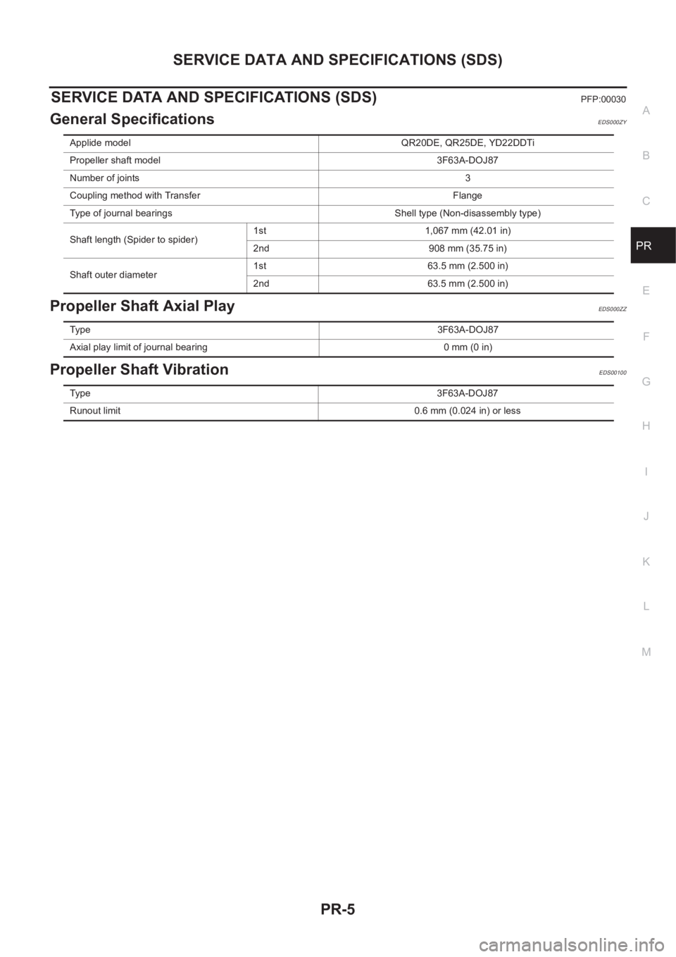
SERVICE DATA AND SPECIFICATIONS (SDS)PFP:00030
General SpecificationsEDS000ZY
Propeller Shaft Axial PlayEDS000ZZ
Propeller Shaft VibrationEDS00100
Applide model QR20DE, QR25DE, YD22DDTi
Propeller shaft model 3F63A-DOJ87
Number of joints3
Coupling method with Transfer Flange
Type of journal bearings Shell type (Non-disassembly type)
Shaft length (Spider to spider)1st 1,067 mm (42.01 in)
2nd 908 mm (35.75 in)
Shaft outer diameter1st 63.5 mm (2.500 in)
2nd 63.5 mm (2.500 in)
Ty p e3F63A-DOJ87
Axial play limit of journal bearing 0 mm (0 in)
Ty p e3F63A-DOJ87
Runout limit 0.6 mm (0.024 in) or less
Page 2758 of 3833

BR-18
BRAKE BOOSTER
INSPECTION AFTER REMOVAL
Output rod length inspection
1. Using a handy vacuum pump, apply a vacuum of -66.7 kPa (-500 mmHg, -19.69 inHg) to the brake
booster.
2. Check output rod length.
3.
INSTALLATION
1. Loosen lock nut to adjust input rod length so that length “B” (in
the figure) satisfies the specified value.
2. After adjusting B, temporarily tighten lock nut to install booster
assembly to vehicle.
3. Connect brake pedal to input rod clevis.
4. Connect brake pedal assembly mounting nuts and tighten to the
specified torque.
5. Connect master cylinder to the booster assembly.
6. Adjust brake pedal height and play.
7. Tighten input rod lock nut to the specified torque.
8. Bleed air. Refer to BR-10, "
Bleeding Brake System" . Reference value at vacuum of -66.7 kPa (-500 mmHg, -
19.69 inHg):
10.4 mm (0.409 in)
SBR208E
Length “B” standard : 125 mm (4.92 in)
SGIA0060E
Page 2772 of 3833

BR-32
SERVICE DATA AND SPECIFICATIONS (SDS)
SERVICE DATA AND SPECIFICATIONS (SDS)
PFP:00030
General SpecificationsEFS000CQ
Unit: mm (in)
Brake PedalEFS000CR
Check ValveEFS000CS
Brake BoosterEFS000CT
Vacuum type
Front Disc BrakeEFS000CU
Front brakeBrake model AD31VD
Cylinder bore diameter 44.4 × 2 (1.748 × 0.08)
Pad
Length x width x thickness132.0 × 52.5 × 11.0
(5.20 × 2.067 × 0.433)
Rotor outer diameter x thickness 280 × 28 (11.02 × 1.10)
Rear brakeBrake model AD9VA
Cylinder bore diameter 34.9 (1.374)
Pad
Length x width x thickness83.0 × 33.0 × 8.5
(3.268 × 1.299 × 0.335)
Rotor outer diameter x thickness 292 × 16 (11.50 × 0.63)
Master cylinder Cylinder bore diameter 25.4 (1)
Control valve Valve model Electronic control type
Brake boosterBooster model C215T
Diaphragm diameterPrimary 230 (9.06)
Secondary 205 (8.07)
Recommended brake fluid DOT 3 or DOT 4
Free play (at pedal top surface) 3 - 11 mm (0.12 - 0.43 in)
Looseness at clevis pin 1 - 3 mm (0.04 - 0.12 in)
Brake pedal height (from dash panel top surface)M/T model 156 - 166 mm (6.14 - 6.54 in)
A/T model 164 - 174 mm (6.46 - 6.85 in)
Depressed pedal height under force of 490 N (50 kg,110.6 lb)
(from dash panel top surface)M/T model 80 mm (3.15 in) or more
A/T model 85 mm (3.35 in) or more
Clearance between threaded end of stop lamp switch and pedal stopper 0.74 - 1.96 mm (0.0291 - 0.0772 in)
Vacuum leakage [at vacuum of 66.7 kPa (-500 mmHg, -19.69
inHg)]Within 1.3 kPa (10 mmHg, 0.39 inHg) of vacuum for 15 sec-
onds
Vacuum leakage [at vacuum of -66.7 kPa (-500 mmHg, -19.69
inHg)]Within 3.3 kPa (25 mmHg, 0.98 inHg) of vacuum for 15 sec-
onds
Input rod installation standard dimension 125 mm (4.92 in)
Brake typeAD31VD
Brake padStandard thickness (new) 11 mm (0.43 in)
Repair limit thickness 2.0 mm (0.07 in)
Disc rotorStandard thickness (new) 28 mm (1.10 in)
Repair limit thickness 26 mm (1.02 in)
Runout limit 0.04 mm (0.0016 in)
Page 2932 of 3833

PS-22
POWER STEERING GEAR AND LINKAGE
25. Position boot band on large-diameter side before installing it.
26. Install small-diameter side of boot to inner socket boot mounting
groove.
27. Install boot band to small-diameter side of boot.
28. Install boot clamp.
a. Tighten large-diameter side of RH/LH boot with boot clamp
(stainless wire).
b. Wrap clamp around boot groove for two turns. Insert screwdriv-
ers in loops on both ends of wire. Twist 4 to 4.5 turns while pull-
ing them with force of approx. 98 N (10 kg, 22.1 lb).
c. Twist boot clamp as shown. Pay attention to relationship
between winding and twisting directions.
d. Twisted point should face front of vehicle with gear installed on
vehicle (to prevent interference with other parts).
e. After twisting wire 4 to 4.5 turns, bend cut end of wire. Cut end of
wire should not touch boot. Be sure wire end is at least 5 mm
(0.20 in) away from clearance for tube.
SGIA0374E
Wire length ( ): 370 mm (14.57 in)
SST097B
SST440A
SGIA0025E
STC0124D
Page 2933 of 3833

POWER STEERING GEAR AND LINKAGE
PS-23
C
D
E
F
H
I
J
K
L
MA
B
PS
29. Connect lock nut and outer socket to inner socket. Temporarily
tighten lock nut until length of tie rod is within specification.
CAUTION:
Perform toe-in adjustment after this procedure. Length
achieved after toe-in adjustment is not necessarily value given
here.Tie rod length (L) : 169.67 mm (6.68 in)
STC0125D
Page 2946 of 3833

PS-36
SERVICE DATA AND SPECIFICATIONS (SDS)
SERVICE DATA AND SPECIFICATIONS (SDS)
PFP:00030
WheelEGS0004P
Steering AngleEGS0004Q
Steering ColumnEGS0004R
Steering LinkageEGS0004S
Steering wheel axial endplay: 0 mm (0 in)
Steering wheel free play 0 - 35 mm (0 - 1.38 in)
Inner wheel Minimum 36°
Nominal 39°
Maximum 40°
Outer wheel31°
Steering column length L 543 mm (21.38 in)
STC1136D
Steering gear type PR24AD
Tie rod ball joint outer
socketSwing torque 0.30 - 2.94 N·m (0.03 - 0.30 kg-m, 3 - 26 in-lb)
Measurement on spring balance
(Measuring point: stud bolt hole)4.84 - 47.4 N (0.49 - 4.84 kg, 1.08 - 10.7 lb)
Rotating torque 0.30 - 2.94 N·m (0.03 - 0.30 kg-m, 3 - 26 in-lb)
Axial endplay 0.5 mm (0.02 in) or less
Tie rod ball joint inner
socketSwing torque 1.0 - 7.8 N·m (0.1 - 0.8 kg-m, 9 - 69 in-lb)
Measured value of spring scale (measuring
point: mark)5.2 - 41 N (0.53 - 4.1 kg, 1.17 - 9.07 lb)
Axial endplay 0.2 mm (0.008 in) or less
Tie rod length “L”169.67 mm (6.68 in)
SGIA0462E
Page 2963 of 3833

FRONT DRIVE SHAFT
FAX-15
C
E
F
G
H
I
J
K
L
MA
B
FA X
ASSEMBLY
Transaxle Side
1. Wind serrated part of drive shaft with tape. Install boot band and
boot to shaft. Be careful not to damage boot.
CAUTION:
Discard the old boot band and boot: replace with new ones.
2. Remove protective tape wound around serrated part of shaft.
3. Line up alignment marks which were made when spider assem-
bly was removed. Install spider assembly, with serration chamfer
facing drive shaft.
4. Secure spider assembly with snap ring.
CAUTION:
Discard the old snap ring: replace with new ones.
5. Apply Nissan genuine grease or equivalent to spider assembly
and sliding surface.
6. Install sliding joint housing to spider assembly. Add remaining
grease up to the amount listed below.
7. Install boot securely into grooves (indicated by * marks) shown
in the figure.
CAUTION:
If there is grease on boot mounting surfaces (indicated by *
marks) of joint, boot may come off. Remove all grease from
surfaces.
8. Check that boot installation length “L” is the length indicated
below. Insert flat bladed screwdriver or similar tool into smaller
side of boot. Remove air from boot to prevent boot deformation.
CAUTION:
●Boot may break if boot installation length is less than
standard value.
●Be careful that screwdriver tip does not contact inside
surface of boot.
SDIA0597E
Grease amount : 133 - 143 g (4.69 - 5.04 oz)
SDIA0598E
SDIA0599E
Boot installation length:
84 - 86 mm (3.31 - 3.39 in)
SDIA0600E
Page 2965 of 3833

SERVICE DATA AND SPECIFICATIONS (SDS)
FAX-17
C
E
F
G
H
I
J
K
L
MA
B
FA X
SERVICE DATA AND SPECIFICATIONS (SDS)PFP:00030
Wheel BearingEDS000IG
Drive ShaftEDS000IH
ZF100SS86, ZF100SS86F, ZF100SS86F+B
Wheel side ZF100 type joint assembly cannot be disassembly because a plastic boot and special boot band are used. Do not use other
drive shaft boots. If the boot or joint is damaged, replace the drive shaft assembly.
Dynamic DamperEDS000II
Drive type 4WD
Rotation torque 1.645 N·m (0.168 kg-m, 15 in-lb) or less
Spring balance reading 10.6 N (1.1 kg, 2.4 lb) or less
Installation location of spring scale
Axial end play 0.05 mm (0.0020 in) or less
SDIA0148E
Joint type
Transaxle side and
transfer sideSS86, SS86F, SS86F+B
Grease amount133 - 143 g (4.69 - 5.04 oz)
Boot length84 - 86 mm (3.31 - 3.39 in)
Transaxle-side and transfer-
side spider assembliesStamped No. Part No. Model
0 39720 8H300
SS86, SS86F, SS86F+B 1 39720 8H301
2 39720 8H302
Drive shaft model Applied model Specification Dimension A Dimension B
ZF100SS86 ALL Left 207 - 213 mm (8.15 - 8.39 in) 70 mm (2.76 in)
ZF100SS86F RHD: QR20DE A/T models
Right267 - 273 mm (10.51 - 10.75 in 68 mm (2.68 in)
ZF100SS86F+ BLHD: QR20DE A/T models
RHD: QR25DE A/T models
QR25DE: M/T models267 - 273 mm (10.51 - 10.75 in)70 mm (2.76 in)
QR20DE/YD22DDTi M/T models 50 mm (1.97 in)
FAC0156D
Page 2979 of 3833
REAR DRIVE SHAFT
RAX-13
C
E
F
G
H
I
J
K
L
MA
B
RAX
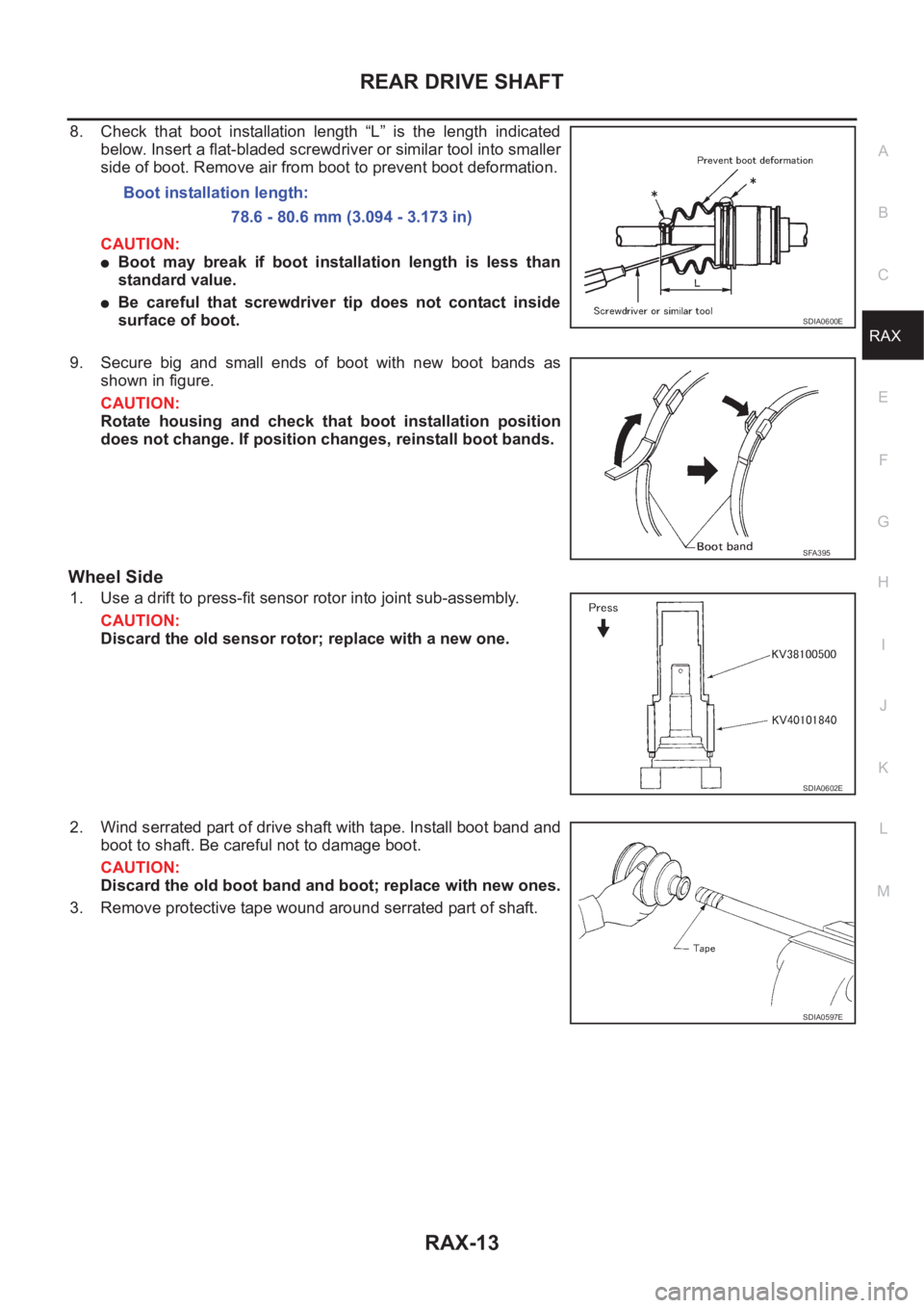
8. Check that boot installation length “L” is the length indicated
below. Insert a flat-bladed screwdriver or similar tool into smaller
side of boot. Remove air from boot to prevent boot deformation.
CAUTION:
●Boot may break if boot installation length is less than
standard value.
●Be careful that screwdriver tip does not contact inside
surface of boot.
9. Secure big and small ends of boot with new boot bands as
shown in figure.
CAUTION:
Rotate housing and check that boot installation position
does not change. If position changes, reinstall boot bands.
Wheel Side
1. Use a drift to press-fit sensor rotor into joint sub-assembly.
CAUTION:
Discard the old sensor rotor; replace with a new one.
2. Wind serrated part of drive shaft with tape. Install boot band and
boot to shaft. Be careful not to damage boot.
CAUTION:
Discard the old boot band and boot; replace with new ones.
3. Remove protective tape wound around serrated part of shaft.Boot installation length:
78.6 - 80.6 mm (3.094 - 3.173 in)
SDIA0600E
SFA395
SDIA0602E
SDIA0597E
Page 2980 of 3833
RAX-14
REAR DRIVE SHAFT
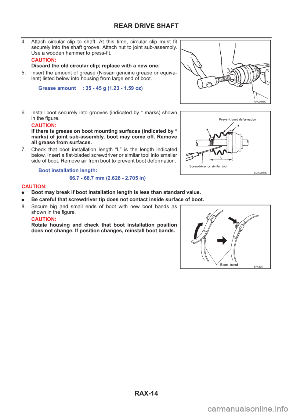
4. Attach circular clip to shaft. At this time, circular clip must fit
securely into the shaft groove. Attach nut to joint sub-assembly.
Use a wooden hammer to press-fit.
CAUTION:
Discard the old circular clip; replace with a new one.
5. Insert the amount of grease (Nissan genuine grease or equiva-
lent) listed below into housing from large end of boot.
6. Install boot securely into grooves (indicated by * marks) shown
in the figure.
CAUTION:
If there is grease on boot mounting surfaces (indicated by *
marks) of joint sub-assembly, boot may come off. Remove
all grease from surfaces.
7. Check that boot installation length “L” is the length indicated
below. Insert a flat-bladed screwdriver or similar tool into smaller
side of boot. Remove air from boot to prevent boot deformation.
CAUTION:
●Boot may break if boot installation length is less than standard value.
●Be careful that screwdriver tip does not contact inside surface of boot.
8. Secure big and small ends of boot with new boot bands as
shown in the figure.
CAUTION:
Rotate housing and check that boot installation position
does not change. If position changes, reinstall boot bands.Grease amount : 35 - 45 g (1.23 - 1.59 oz)
RAC0049D
Boot installation length:
66.7 - 68.7 mm (2.626 - 2.705 in)SDIA0607E
SFA395