oxygen NISSAN X-TRAIL 2001 Service Owner's Guide
[x] Cancel search | Manufacturer: NISSAN, Model Year: 2001, Model line: X-TRAIL, Model: NISSAN X-TRAIL 2001Pages: 3833, PDF Size: 39.49 MB
Page 451 of 3833
TROUBLE DIAGNOSIS
EC-101
[QR25(WITH EURO-OBD)]
C
D
E
F
G
H
I
J
K
L
MA
EC
NOTE:
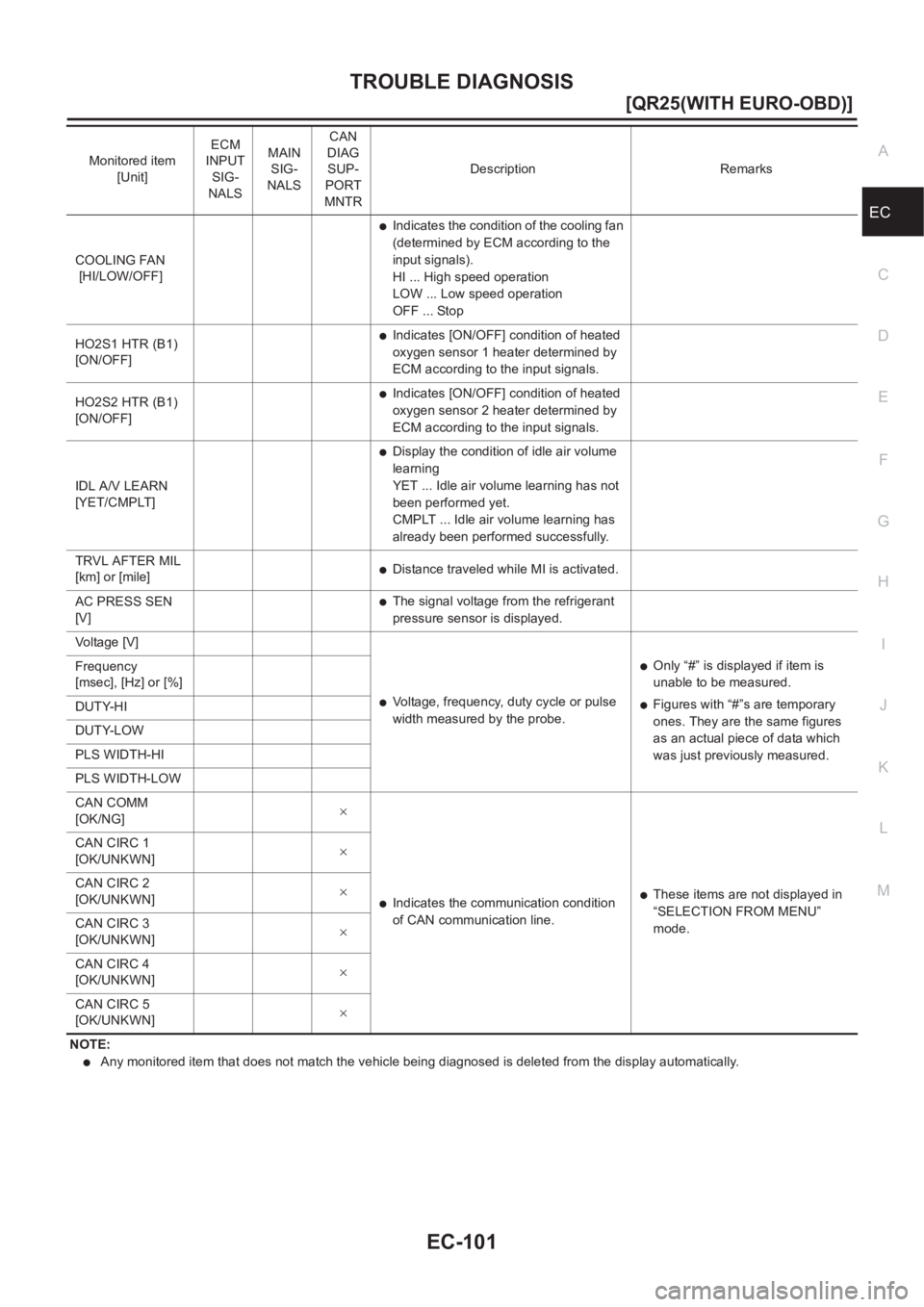
●Any monitored item that does not match the vehicle being diagnosed is deleted from the display automatically. COOLING FAN
[HI/LOW/OFF]
●Indicates the condition of the cooling fan
(determined by ECM according to the
input signals).
HI ... High speed operation
LOW ... Low speed operation
OFF ... Stop
HO2S1 HTR (B1)
[ON/OFF]
●Indicates [ON/OFF] condition of heated
oxygen sensor 1 heater determined by
ECM according to the input signals.
HO2S2 HTR (B1)
[ON/OFF]
●Indicates [ON/OFF] condition of heated
oxygen sensor 2 heater determined by
ECM according to the input signals.
IDL A/V LEARN
[YET/CMPLT]
●Display the condition of idle air volume
learning
YET ... Idle air volume learning has not
been performed yet.
CMPLT ... Idle air volume learning has
already been performed successfully.
TRVL AFTER MIL
[km] or [mile]
●Distance traveled while MI is activated.
AC PRESS SEN
[V]
●The signal voltage from the refrigerant
pressure sensor is displayed.
Voltage [V]
●Voltage, frequency, duty cycle or pulse
width measured by the probe.
●Only “#” is displayed if item is
unable to be measured.
●Figures with “#”s are temporary
ones. They are the same figures
as an actual piece of data which
was just previously measured. Frequency
[msec], [Hz] or [%]
DUTY-HI
DUTY-LOW
PLS WIDTH-HI
PLS WIDTH-LOW
CAN COMM
[OK/NG]×
●Indicates the communication condition
of CAN communication line.●These items are not displayed in
“SELECTION FROM MENU”
mode. CAN CIRC 1
[OK/UNKWN]×
CAN CIRC 2
[OK/UNKWN]×
CAN CIRC 3
[OK/UNKWN]×
CAN CIRC 4
[OK/UNKWN]×
CAN CIRC 5
[OK/UNKWN]× Monitored item
[Unit]ECM
INPUT
SIG-
NALSMAIN
SIG-
NALSCAN
DIAG
SUP-
PORT
MNTRDescription Remarks
Page 452 of 3833
EC-102
[QR25(WITH EURO-OBD)]
TROUBLE DIAGNOSIS
DATA MONITOR (SPEC) MODE
Monitored Item
NOTE:
●Any monitored item that does not match the vehicle being diagnosed is deleted from the display automatically.
ACTIVE TEST MODE
Test Item
Monitored item [Unit]ECM
input
signalsMain
signalsDescription Remarks
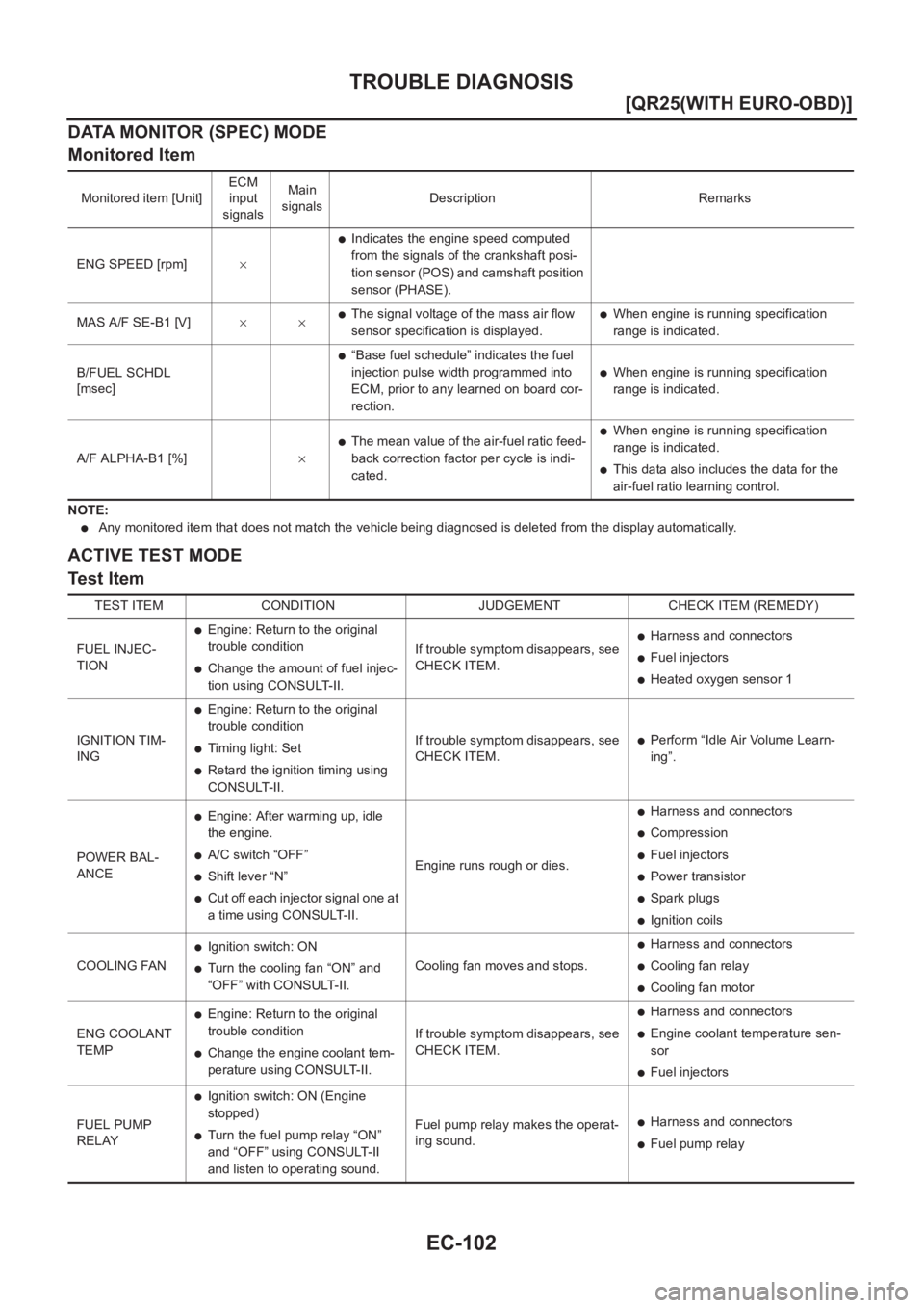
ENG SPEED [rpm]×
●Indicates the engine speed computed
from the signals of the crankshaft posi-
tion sensor (POS) and camshaft position
sensor (PHASE).
MAS A/F SE-B1 [V]××
●The signal voltage of the mass air flow
sensor specification is displayed.●When engine is running specification
range is indicated.
B/FUEL SCHDL
[msec]
●“Base fuel schedule” indicates the fuel
injection pulse width programmed into
ECM, prior to any learned on board cor-
rection.
●When engine is running specification
range is indicated.
A/F ALPHA-B1 [%]×
●The mean value of the air-fuel ratio feed-
back correction factor per cycle is indi-
cated.●When engine is running specification
range is indicated.
●This data also includes the data for the
air-fuel ratio learning control.
TEST ITEM CONDITION JUDGEMENT CHECK ITEM (REMEDY)
FUEL INJEC-
TION
●Engine: Return to the original
trouble condition
●Change the amount of fuel injec-
tion using CONSULT-II.If trouble symptom disappears, see
CHECK ITEM.
●Harness and connectors
●Fuel injectors
●Heated oxygen sensor 1
IGNITION TIM-
ING
●Engine: Return to the original
trouble condition
●Timing light: Set
●Retard the ignition timing using
CONSULT-II.If trouble symptom disappears, see
CHECK ITEM.
●Perform “Idle Air Volume Learn-
ing”.
POWER BAL-
ANCE
●Engine: After warming up, idle
the engine.
●A/C switch “OFF”
●Shift lever “N”
●Cut off each injector signal one at
a time using CONSULT-II.Engine runs rough or dies.
●Harness and connectors
●Compression
●Fuel injectors
●Power transistor
●Spark plugs
●Ignition coils
COOLING FAN
●Ignition switch: ON
●Turn the cooling fan “ON” and
“OFF” with CONSULT-II.Cooling fan moves and stops.
●Harness and connectors
●Cooling fan relay
●Cooling fan motor
ENG COOLANT
TEMP
●Engine: Return to the original
trouble condition
●Change the engine coolant tem-
perature using CONSULT-II.If trouble symptom disappears, see
CHECK ITEM.
●Harness and connectors
●Engine coolant temperature sen-
sor
●Fuel injectors
FUEL PUMP
RELAY
●Ignition switch: ON (Engine
stopped)
●Turn the fuel pump relay “ON”
and “OFF” using CONSULT-II
and listen to operating sound.Fuel pump relay makes the operat-
ing sound.●Harness and connectors
●Fuel pump relay
Page 478 of 3833
EC-128
[QR25(WITH EURO-OBD)]
DTC P0031, P0032 HO2S1 HEATER
DTC P0031, P0032 HO2S1 HEATER
PFP:22690
DescriptionEBS00M1Q
SYSTEM DESCRIPTION
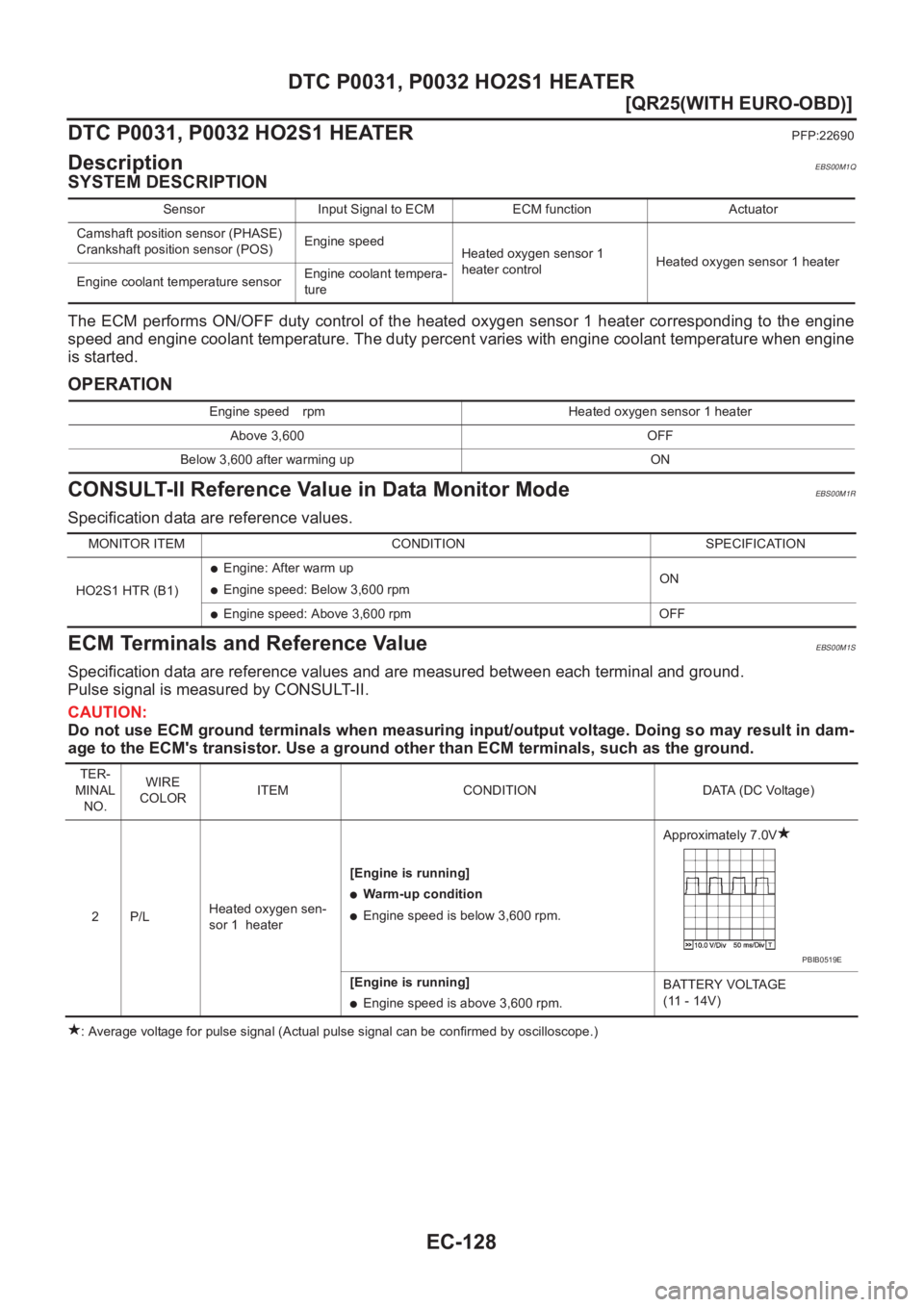
The ECM performs ON/OFF duty control of the heated oxygen sensor 1 heater corresponding to the engine
speed and engine coolant temperature. The duty percent varies with engine coolant temperature when engine
is started.
OPERATION
CONSULT-II Reference Value in Data Monitor ModeEBS00M1R
Specification data are reference values.
ECM Terminals and Reference ValueEBS00M1S
Specification data are reference values and are measured between each terminal and ground.
Pulse signal is measured by CONSULT-II.
CAUTION:
Do not use ECM ground terminals when measuring input/output voltage. Doing so may result in dam-
age to the ECM's transistor. Use a ground other than ECM terminals, such as the ground.
: Average voltage for pulse signal (Actual pulse signal can be confirmed by oscilloscope.) Sensor Input Signal to ECM ECM function Actuator
Camshaft position sensor (PHASE)
Crankshaft position sensor (POS)Engine speed
Heated oxygen sensor 1
heater controlHeated oxygen sensor 1 heater
Engine coolant temperature sensorEngine coolant tempera-
ture
Engine speed rpm Heated oxygen sensor 1 heater
Above 3,600 OFF
Below 3,600 after warming up ON
MONITOR ITEM CONDITION SPECIFICATION
HO2S1 HTR (B1)
●Engine: After warm up
●Engine speed: Below 3,600 rpmON
●Engine speed: Above 3,600 rpm OFF
TER-
MINAL
NO.WIRE
COLORITEM CONDITION DATA (DC Voltage)
2P/LHeated oxygen sen-
sor 1 heater[Engine is running]
●Warm-up condition
●Engine speed is below 3,600 rpm.Approximately 7.0V
[Engine is running]
●Engine speed is above 3,600 rpm.BATTERY VOLTAGE
(11 - 14V)
PBIB0519E
Page 479 of 3833
DTC P0031, P0032 HO2S1 HEATER
EC-129
[QR25(WITH EURO-OBD)]
C
D
E
F
G
H
I
J
K
L
MA
EC
On Board Diagnosis LogicEBS00M1T
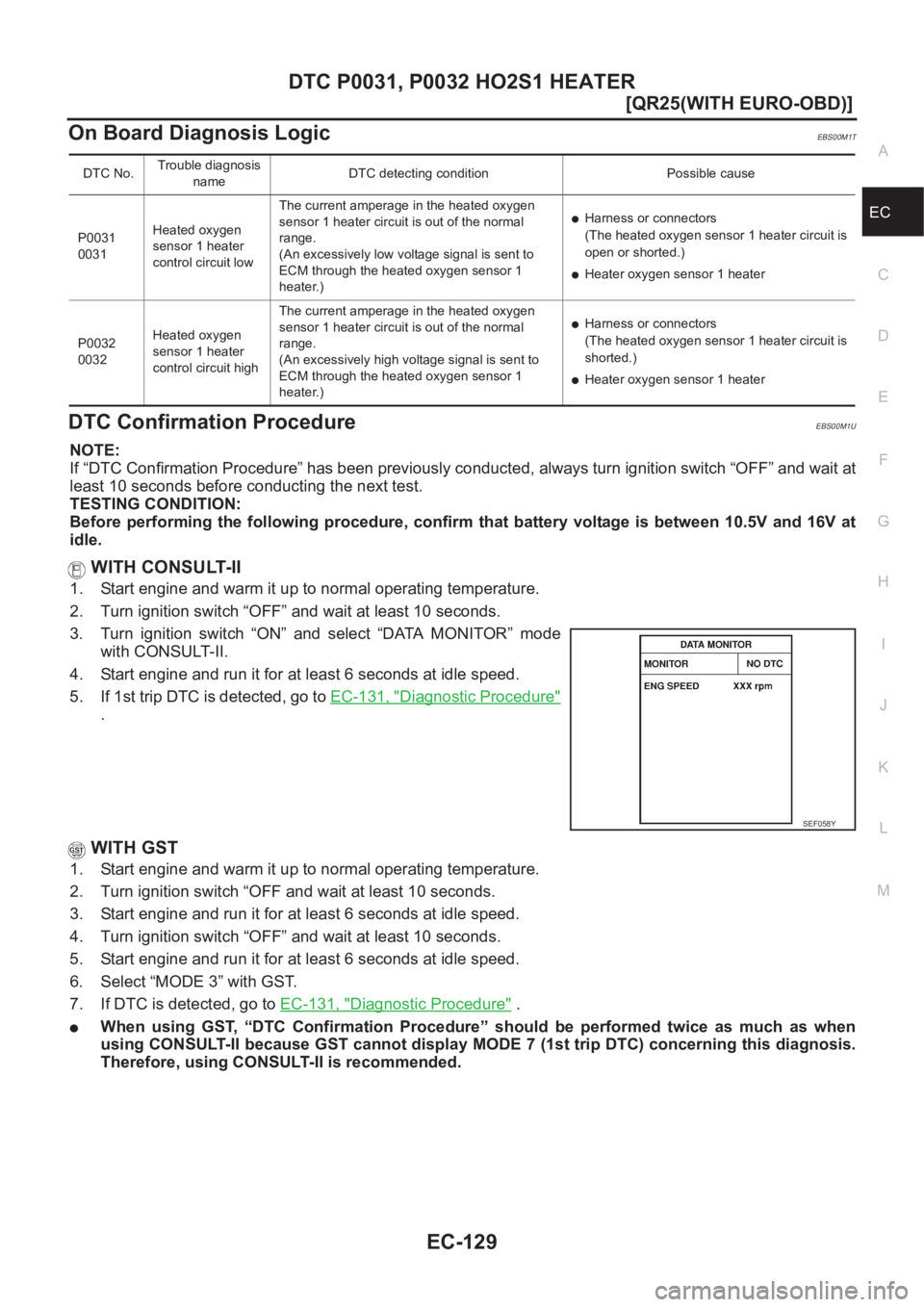
DTC Confirmation ProcedureEBS00M1U
NOTE:
If “DTC Confirmation Procedure” has been previously conducted, always turn ignition switch “OFF” and wait at
least 10 seconds before conducting the next test.
TESTING CONDITION:
Before performing the following procedure, confirm that battery voltage is between 10.5V and 16V at
idle.
WITH CONSULT-II
1. Start engine and warm it up to normal operating temperature.
2. Turn ignition switch “OFF” and wait at least 10 seconds.
3. Turn ignition switch “ON” and select “DATA MONITOR” mode
with CONSULT-II.
4. Start engine and run it for at least 6 seconds at idle speed.
5. If 1st trip DTC is detected, go to EC-131, "
Diagnostic Procedure"
.
WITH GST
1. Start engine and warm it up to normal operating temperature.
2. Turn ignition switch “OFF and wait at least 10 seconds.
3. Start engine and run it for at least 6 seconds at idle speed.
4. Turn ignition switch “OFF” and wait at least 10 seconds.
5. Start engine and run it for at least 6 seconds at idle speed.
6. Select “MODE 3” with GST.
7. If DTC is detected, go to EC-131, "
Diagnostic Procedure" .
●When using GST, “DTC Confirmation Procedure” should be performed twice as much as when
using CONSULT-II because GST cannot display MODE 7 (1st trip DTC) concerning this diagnosis.
Therefore, using CONSULT-II is recommended.
DTC No.Trouble diagnosis
nameDTC detecting condition Possible cause
P0031
0031Heated oxygen
sensor 1 heater
control circuit lowThe current amperage in the heated oxygen
sensor 1 heater circuit is out of the normal
range.
(An excessively low voltage signal is sent to
ECM through the heated oxygen sensor 1
heater.)
●Harness or connectors
(The heated oxygen sensor 1 heater circuit is
open or shorted.)
●Heater oxygen sensor 1 heater
P0032
0032Heated oxygen
sensor 1 heater
control circuit highThe current amperage in the heated oxygen
sensor 1 heater circuit is out of the normal
range.
(An excessively high voltage signal is sent to
ECM through the heated oxygen sensor 1
heater.)
●Harness or connectors
(The heated oxygen sensor 1 heater circuit is
shorted.)
●Heater oxygen sensor 1 heater
SEF058Y
Page 481 of 3833
DTC P0031, P0032 HO2S1 HEATER
EC-131
[QR25(WITH EURO-OBD)]
C
D
E
F
G
H
I
J
K
L
MA
EC
Diagnostic ProcedureEBS00M1W
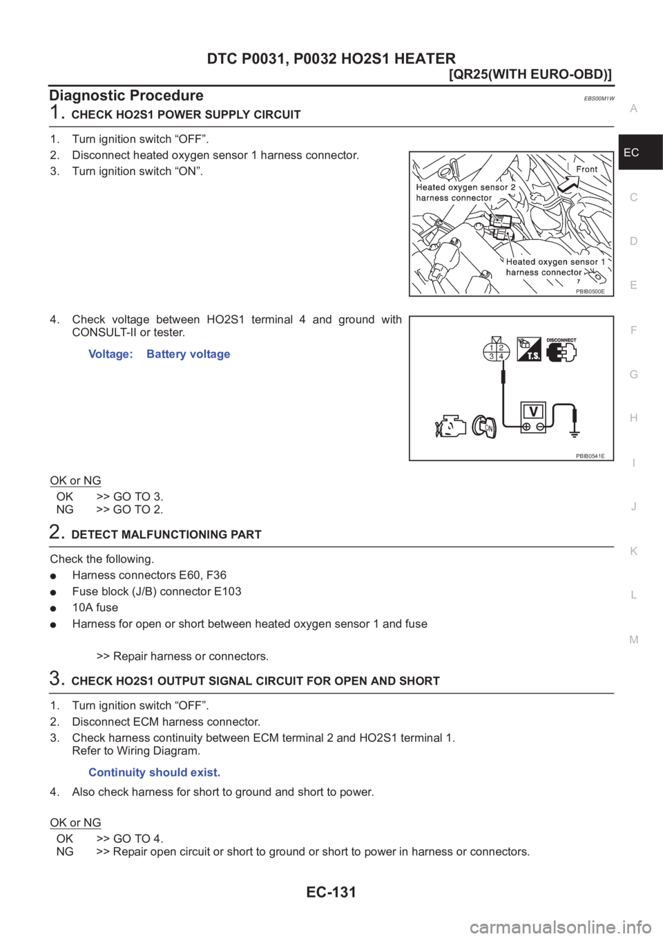
1.CHECK HO2S1 POWER SUPPLY CIRCUIT
1. Turn ignition switch “OFF”.
2. Disconnect heated oxygen sensor 1 harness connector.
3. Turn ignition switch “ON”.
4. Check voltage between HO2S1 terminal 4 and ground with
CONSULT-II or tester.
OK or NG
OK >> GO TO 3.
NG >> GO TO 2.
2.DETECT MALFUNCTIONING PART
Check the following.
●Harness connectors E60, F36
●Fuse block (J/B) connector E103
●10A fuse
●Harness for open or short between heated oxygen sensor 1 and fuse
>> Repair harness or connectors.
3.CHECK HO2S1 OUTPUT SIGNAL CIRCUIT FOR OPEN AND SHORT
1. Turn ignition switch “OFF”.
2. Disconnect ECM harness connector.
3. Check harness continuity between ECM terminal 2 and HO2S1 terminal 1.
Refer to Wiring Diagram.
4. Also check harness for short to ground and short to power.
OK or NG
OK >> GO TO 4.
NG >> Repair open circuit or short to ground or short to power in harness or connectors.
PBIB0500E
Voltage: Battery voltage
PBIB0541E
Continuity should exist.
Page 482 of 3833
EC-132
[QR25(WITH EURO-OBD)]
DTC P0031, P0032 HO2S1 HEATER
4. CHECK HEATED OXYGEN SENSOR 1 HEATER
Refer to EC-132, "
Component Inspection" .
OK or NG
OK >> GO TO 5.
NG >> Replace heated oxygen sensor 1.
5. CHECK INTERMITTENT INCIDENT
Refer to EC-115, "
TROUBLE DIAGNOSIS FOR INTERMITTENT INCIDENT" .
>>INSPECTION END
Component InspectionEBS00M1X
HEATED OXYGEN SENSOR 1 HEATER
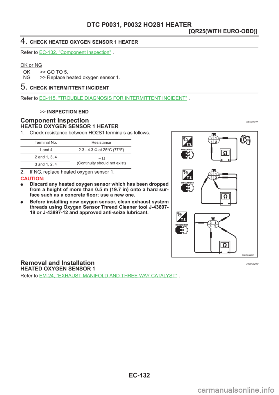
1. Check resistance between HO2S1 terminals as follows.
2. If NG, replace heated oxygen sensor 1.
CAUTION:
●Discard any heated oxygen sensor which has been dropped
from a height of more than 0.5 m (19.7 in) onto a hard sur-
face such as a concrete floor; use a new one.
●Before installing new oxygen sensor, clean exhaust system
threads using Oxygen Sensor Thread Cleaner tool J-43897-
18 or J-43897-12 and approved anti-seize lubricant.
Removal and InstallationEBS00M1Y
HEATED OXYGEN SENSOR 1
Refer to EM-24, "EXHAUST MANIFOLD AND THREE WAY CATALYST" .
Terminal No. Resistance
1 and 4 2.3 - 4.3 Ω at 25°C (77°F)
2 and 1, 3, 4
∞Ω
(Continuity should not exist)
3 and 1, 2, 4
PBIB0542E
Page 483 of 3833
DTC P0037, P0038 HO2S2 HEATER
EC-133
[QR25(WITH EURO-OBD)]
C
D
E
F
G
H
I
J
K
L
MA
EC
DTC P0037, P0038 HO2S2 HEATERPFP:226A0
DescriptionEBS00M1Z
SYSTEM DESCRIPTION
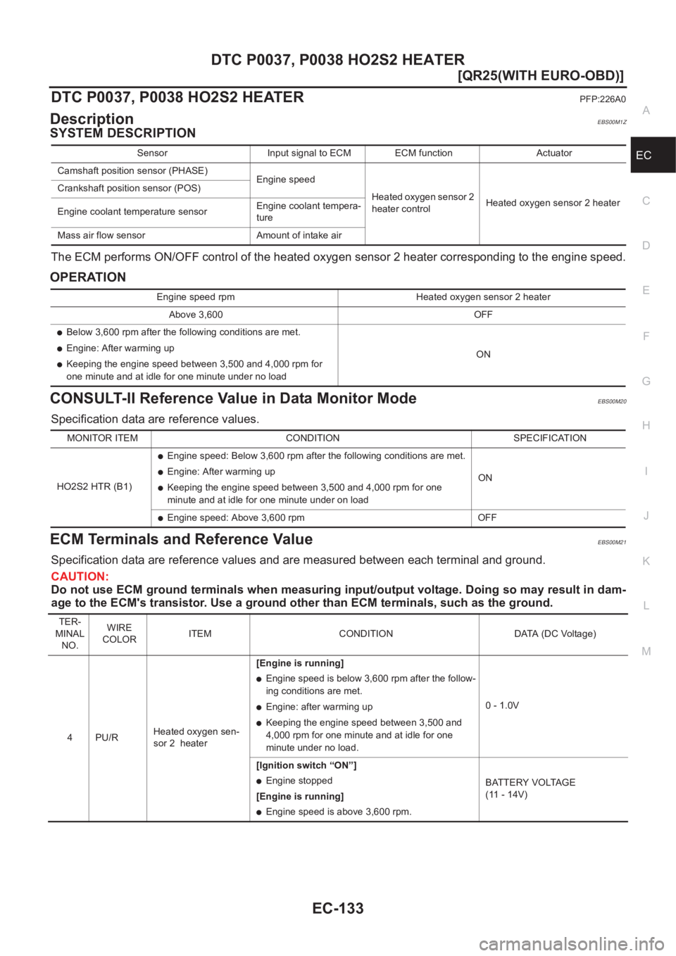
The ECM performs ON/OFF control of the heated oxygen sensor 2 heater corresponding to the engine speed.
OPERATION
CONSULT-II Reference Value in Data Monitor ModeEBS00M20
Specification data are reference values.
ECM Terminals and Reference ValueEBS00M21
Specification data are reference values and are measured between each terminal and ground.
CAUTION:
Do not use ECM ground terminals when measuring input/output voltage. Doing so may result in dam-
age to the ECM's transistor. Use a ground other than ECM terminals, such as the ground.
Sensor Input signal to ECM ECM function Actuator
Camshaft position sensor (PHASE)
Engine speed
Heated oxygen sensor 2
heater controlHeated oxygen sensor 2 heater Crankshaft position sensor (POS)
Engine coolant temperature sensorEngine coolant tempera-
ture
Mass air flow sensor Amount of intake air
Engine speed rpm Heated oxygen sensor 2 heater
Above 3,600 OFF
●Below 3,600 rpm after the following conditions are met.
●Engine: After warming up
●Keeping the engine speed between 3,500 and 4,000 rpm for
one minute and at idle for one minute under no loadON
MONITOR ITEM CONDITION SPECIFICATION
HO2S2 HTR (B1)
●Engine speed: Below 3,600 rpm after the following conditions are met.
●Engine: After warming up
●Keeping the engine speed between 3,500 and 4,000 rpm for one
minute and at idle for one minute under on loadON
●Engine speed: Above 3,600 rpm OFF
TER-
MINAL
NO.WIRE
COLORITEM CONDITION DATA (DC Voltage)
4PU/RHeated oxygen sen-
sor 2 heater[Engine is running]
●Engine speed is below 3,600 rpm after the follow-
ing conditions are met.
●Engine: after warming up
●Keeping the engine speed between 3,500 and
4,000 rpm for one minute and at idle for one
minute under no load.0 - 1.0V
[Ignition switch “ON”]
●Engine stopped
[Engine is running]
●Engine speed is above 3,600 rpm.BATTERY VOLTAGE
(11 - 14V)
Page 484 of 3833
EC-134
[QR25(WITH EURO-OBD)]
DTC P0037, P0038 HO2S2 HEATER
On Board Diagnosis Logic
EBS00M22
DTC Confirmation ProcedureEBS00M23
NOTE:
If “DTC Confirmation Procedure” has been previously conducted, always turn ignition switch “OFF” and wait at
least 10 seconds before conducting the next test.
TESTING CONDITION:
Before performing the following procedure, confirm that battery voltage is between 10.5V and 16V at
idle.
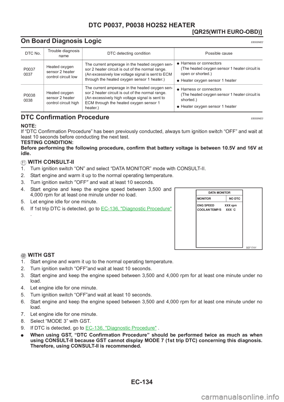
WITH CONSULT-II
1. Turn ignition switch “ON” and select “DATA MONITOR” mode with CONSULT-II.
2. Start engine and warm it up to the normal operating temperature.
3. Turn ignition switch ″OFF″ and wait at least 10 seconds.
4. Start engine and keep the engine speed between 3,500 and
4,000 rpm for at least one minute under no load.
5. Let engine idle for one minute.
6. If 1st trip DTC is detected, go to EC-136, "
Diagnostic Procedure"
.
WITH GST
1. Start engine and warm it up to the normal operating temperature.
2. Turn ignition switch “OFF”and wait at least 10 seconds.
3. Start engine and keep the engine speed between 3,500 and 4,000 rpm for at least one minute under no
load.
4. Let engine idle for one minute.
5. Turn ignition switch “OFF”and wait at least 10 seconds.
6. Start engine and keep the engine speed between 3,500 and 4,000 rpm for at least one minute under no
load.
7. Let engine idle for one minute.
8. Select “MODE 3” with GST.
9. If DTC is detected, go to EC-136, "
Diagnostic Procedure" .
●When using GST, “DTC Confirmation Procedure” should be performed twice as much as when
using CONSULT-II because GST cannot display MODE 7 (1st trip DTC) concerning this diagnosis.
Therefore, using CONSULT-II is recommended.
DTC No.Trouble diagnosis
nameDTC detecting condition Possible cause
P0037
0037Heated oxygen
sensor 2 heater
control circuit lowThe current amperage in the heated oxygen sen-
sor 2 heater circuit is out of the normal range.
(An excessively low voltage signal is sent to ECM
through the heated oxygen sensor 1 heater.)
●Harness or connectors
(The heated oxygen sensor 1 heater circuit is
open or shorted.)
●Heater oxygen sensor 1 heater
P0038
0038Heated oxygen
sensor 2 heater
control circuit highThe current amperage in the heated oxygen sen-
sor 2 heater circuit is out of the normal range.
(An excessively high voltage signal is sent to
ECM through the heated oxygen sensor 1
heater.)
●Harness or connectors
(The heated oxygen sensor 1 heater circuit is
shorted.)
●Heater oxygen sensor 1 heater
SEF174Y
Page 486 of 3833
EC-136
[QR25(WITH EURO-OBD)]
DTC P0037, P0038 HO2S2 HEATER
Diagnostic Procedure
EBS00M25
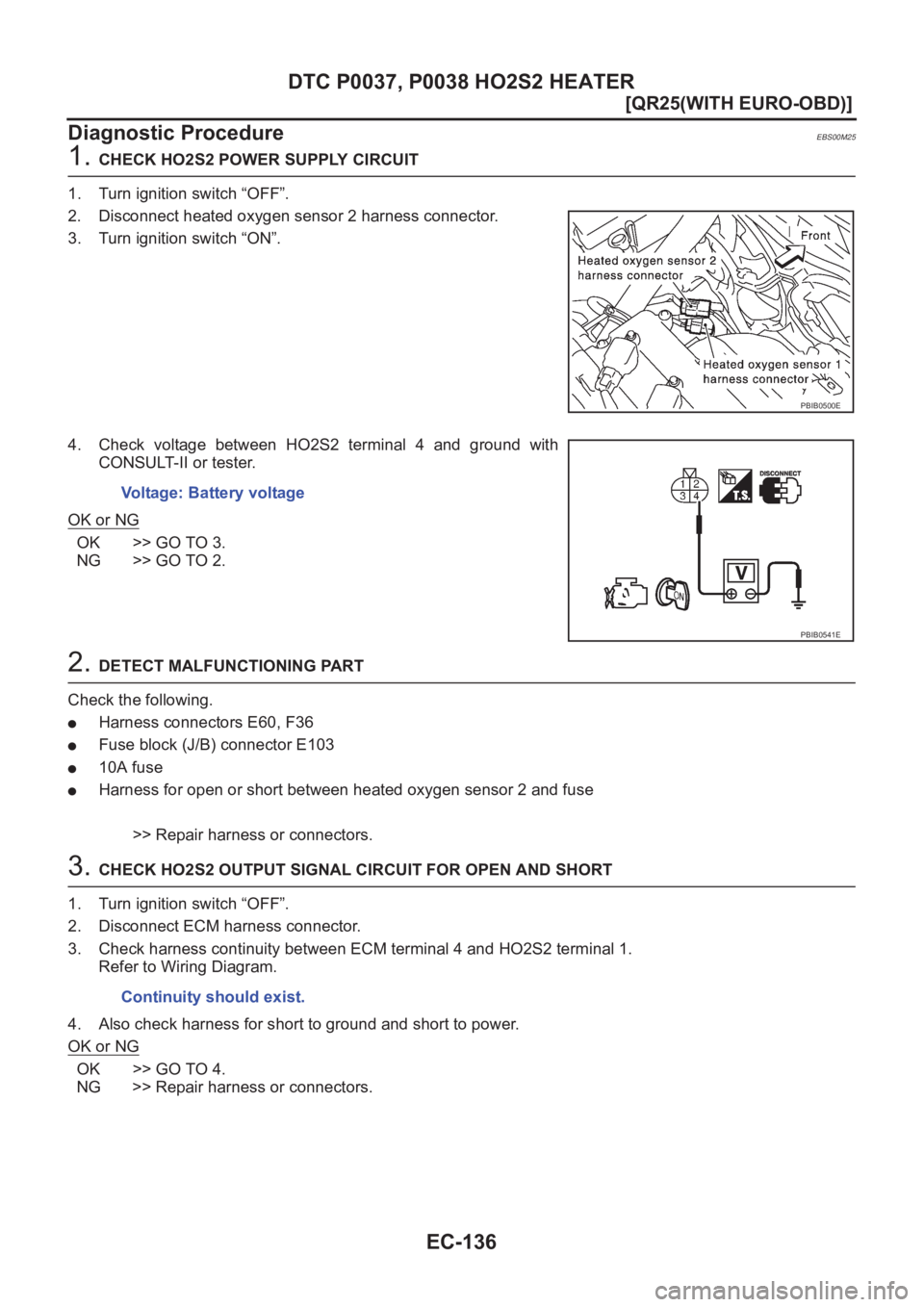
1. CHECK HO2S2 POWER SUPPLY CIRCUIT
1. Turn ignition switch “OFF”.
2. Disconnect heated oxygen sensor 2 harness connector.
3. Turn ignition switch “ON”.
4. Check voltage between HO2S2 terminal 4 and ground with
CONSULT-II or tester.
OK or NG
OK >> GO TO 3.
NG >> GO TO 2.
2. DETECT MALFUNCTIONING PART
Check the following.
●Harness connectors E60, F36
●Fuse block (J/B) connector E103
●10A fuse
●Harness for open or short between heated oxygen sensor 2 and fuse
>> Repair harness or connectors.
3. CHECK HO2S2 OUTPUT SIGNAL CIRCUIT FOR OPEN AND SHORT
1. Turn ignition switch “OFF”.
2. Disconnect ECM harness connector.
3. Check harness continuity between ECM terminal 4 and HO2S2 terminal 1.
Refer to Wiring Diagram.
4. Also check harness for short to ground and short to power.
OK or NG
OK >> GO TO 4.
NG >> Repair harness or connectors.
PBIB0500E
Voltage: Battery voltage
PBIB0541E
Continuity should exist.
Page 487 of 3833
DTC P0037, P0038 HO2S2 HEATER
EC-137
[QR25(WITH EURO-OBD)]
C
D
E
F
G
H
I
J
K
L
MA
EC
4.CHECK HEATED OXYGEN SENSOR 2 HEATER
Refer to EC-137, "
Component Inspection" .
OK or NG
OK >> GO TO 5.
NG >> Replace malfunctioning heated oxygen sensor 2.
5.CHECK INTERMITTENT INCIDENT
Refer to EC-115, "
TROUBLE DIAGNOSIS FOR INTERMITTENT INCIDENT" .
>>INSPECTION END
Component InspectionEBS00M26
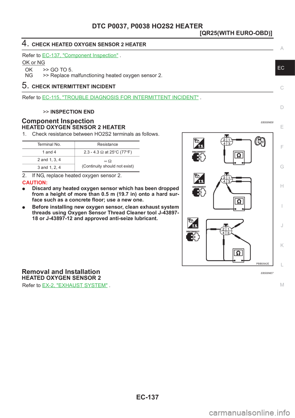
HEATED OXYGEN SENSOR 2 HEATER
1. Check resistance between HO2S2 terminals as follows.
2. If NG, replace heated oxygen sensor 2.
CAUTION:
●Discard any heated oxygen sensor which has been dropped
from a height of more than 0.5 m (19.7 in) onto a hard sur-
face such as a concrete floor; use a new one.
●Before installing new oxygen sensor, clean exhaust system
threads using Oxygen Sensor Thread Cleaner tool J-43897-
18 or J-43897-12 and approved anti-seize lubricant.
Removal and InstallationEBS00M27
HEATED OXYGEN SENSOR 2
Refer to EX-2, "EXHAUST SYSTEM" .
Terminal No. Resistance
1 and 4 2.3 - 4.3 Ω at 25°C (77°F)
2 and 1, 3, 4
∞Ω
(Continuity should not exist)
3 and 1, 2, 4
PBIB0542E