relay NISSAN X-TRAIL 2001 Service Owner's Guide
[x] Cancel search | Manufacturer: NISSAN, Model Year: 2001, Model line: X-TRAIL, Model: NISSAN X-TRAIL 2001Pages: 3833, PDF Size: 39.49 MB
Page 628 of 3833
EC-278
[QR25(WITH EURO-OBD)]
DTC P1122 ELECTRIC THROTTLE CONTROL FUNCTION
DTC P1122 ELECTRIC THROTTLE CONTROL FUNCTION
PFP:16119
DescriptionEBS00NBU
NOTE:
If DTC P1122 is displayed with DTC P1121 or 1126, first perform the trouble diagnosis for DTC P1121 or
P1126. Refer to EC-276
or EC-285 .
Electric Throttle Control Actuator consists of throttle control motor, throttle position sensor, etc.
The throttle control motor is operated by the ECM and it opens and closes the throttle valve.
The current opening angle of the throttle valve is detected by the throttle position sensor and it provides feed-
back to the ECM to control the throttle control motor to make the throttle valve opening angle properly in
response to driving condition.
CONSULT-II Reference Value in Data Monitor ModeEBS00NBV
Specification data are reference values.
ECM Terminals and Reference ValueEBS00NBW
Specification data are reference values and are measured between each terminal and ground.
Pulse signal is measured by CONSULT-II.
CAUTION:
Do not use ECM ground terminals when measuring input/output voltage. Doing so may result in dam-
age to the ECM's transistor. Use a ground other than ECM terminals, such as the ground.
: Average voltage for pulse signal (Actual pulse signal can be confirmed by oscilloscope.) MONITOR ITEM CONDITION SPECIFICATION
THRTL RELAY
●Ignition switch: ON ON
TER-
MINAL
NO.WIRE
COLORITEM CONDITION DATA (DC Voltage)
11 2 W / RThrottle control motor
relay[Ignition switch “OFF”]BATTERY VOLTAGE
(11 - 14V)
[Ignition switch “ON”]0 - 1.0V
11 3 W / BThrottle control motor
relay power supply[Ignition switch “ON”]BATTERY VOLTAGE
(11 - 14V)
11 4 RThrottle control motor
(Open)[Ignition switch “ON”]
●Engine stopped
●Gear position is “D” (A/T model)
●Gear position is “1st” (M/T model)
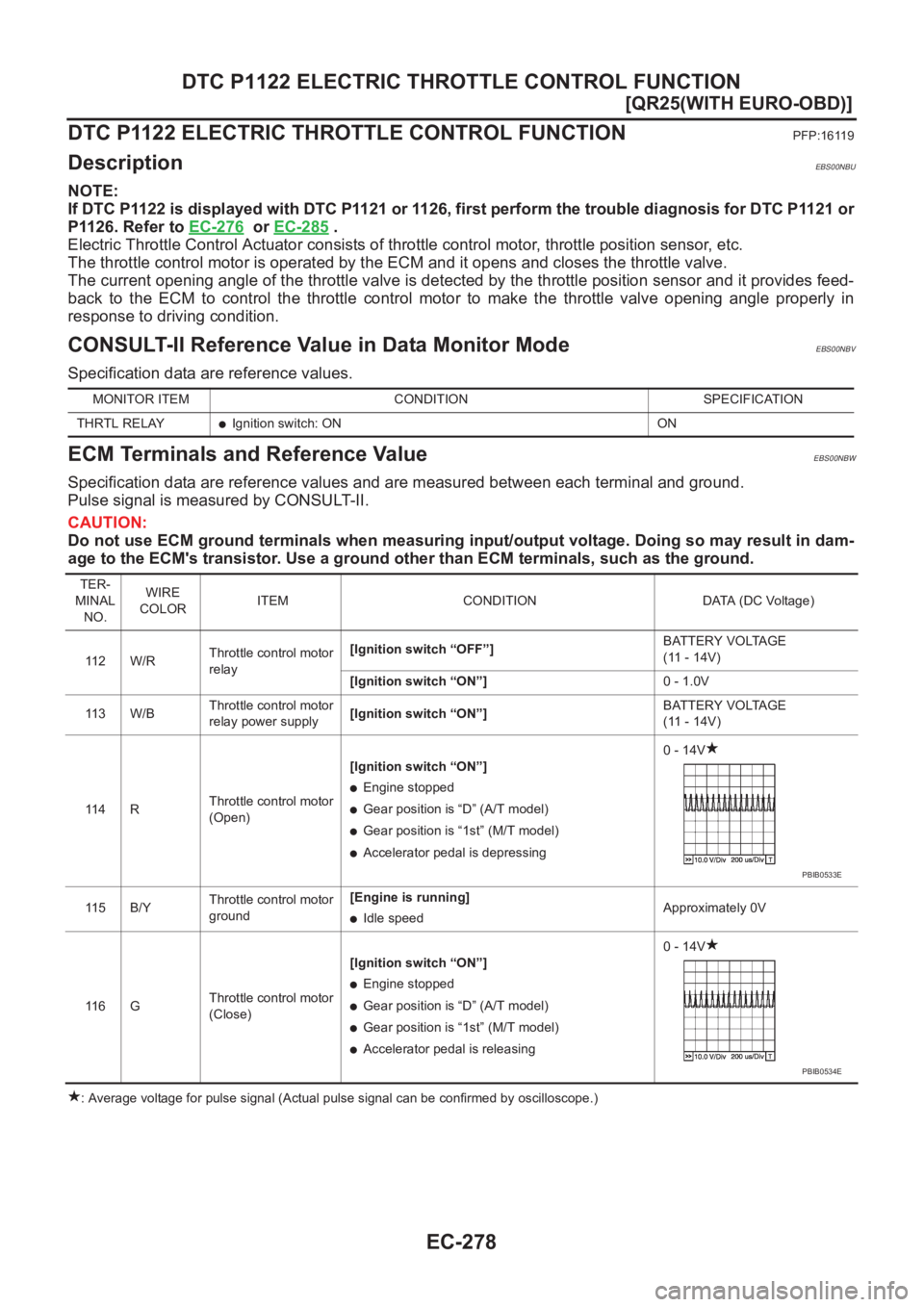
●Accelerator pedal is depressing0 - 14V
11 5 B / YThrottle control motor
ground[Engine is running]
●Idle speedApproximately 0V
11 6 GThrottle control motor
(Close)[Ignition switch “ON”]
●Engine stopped
●Gear position is “D” (A/T model)
●Gear position is “1st” (M/T model)
●Accelerator pedal is releasing0 - 14V
PBIB0533E
PBIB0534E
Page 631 of 3833
DTC P1122 ELECTRIC THROTTLE CONTROL FUNCTION
EC-281
[QR25(WITH EURO-OBD)]
C
D
E
F
G
H
I
J
K
L
MA
EC
Diagnostic ProcedureEBS00NC0
1.RETIGHTEN GROUND SCREWS
1. Turn ignition switch “OFF”.
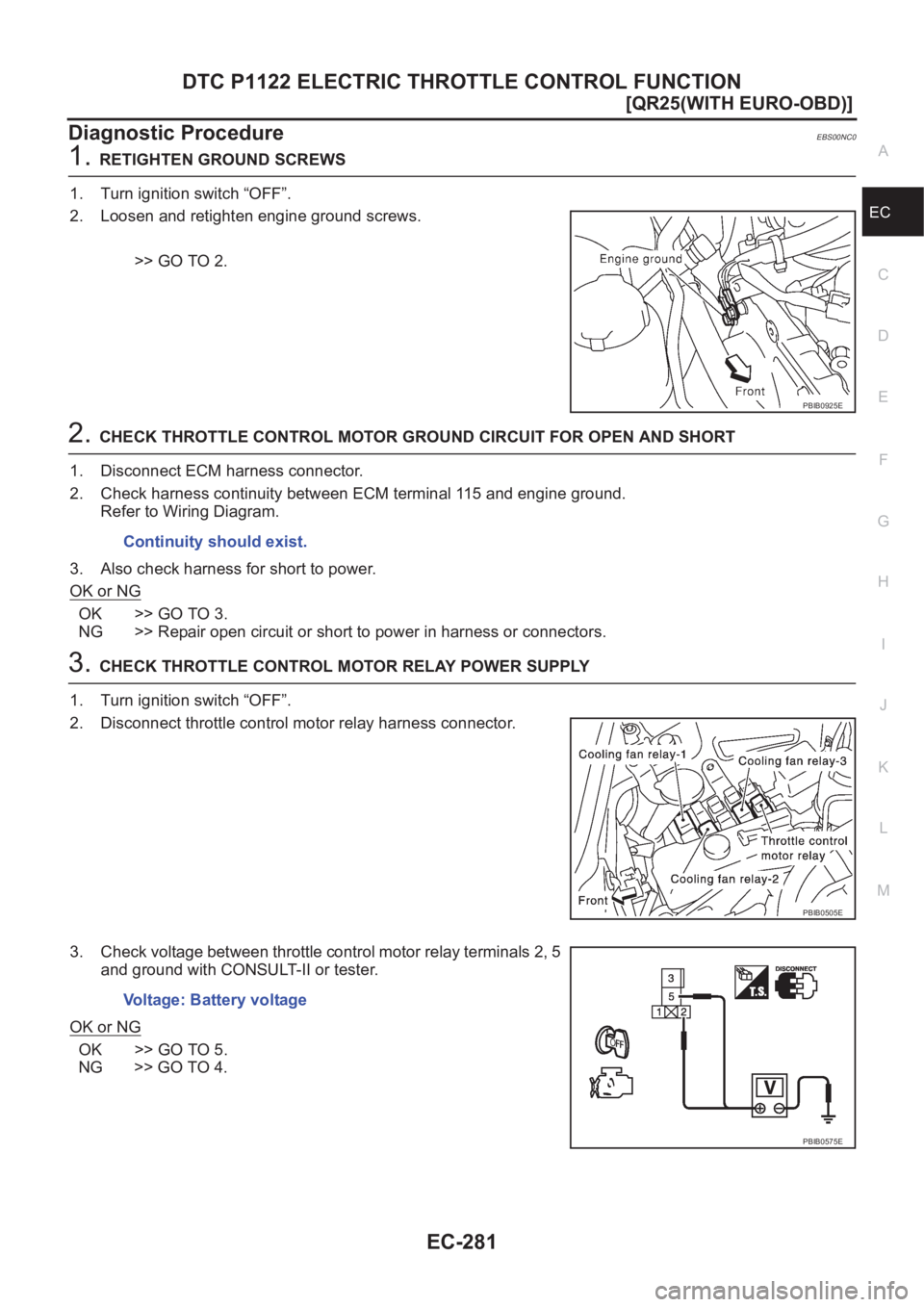
2. Loosen and retighten engine ground screws.
>> GO TO 2.
2.CHECK THROTTLE CONTROL MOTOR GROUND CIRCUIT FOR OPEN AND SHORT
1. Disconnect ECM harness connector.
2. Check harness continuity between ECM terminal 115 and engine ground.
Refer to Wiring Diagram.
3. Also check harness for short to power.
OK or NG
OK >> GO TO 3.
NG >> Repair open circuit or short to power in harness or connectors.
3.CHECK THROTTLE CONTROL MOTOR RELAY POWER SUPPLY
1. Turn ignition switch “OFF”.
2. Disconnect throttle control motor relay harness connector.
3. Check voltage between throttle control motor relay terminals 2, 5
and ground with CONSULT-II or tester.
OK or NG
OK >> GO TO 5.
NG >> GO TO 4.
PBIB0925E
Continuity should exist.
PBIB0505E
Voltage: Battery voltage
PBIB0575E
Page 632 of 3833
EC-282
[QR25(WITH EURO-OBD)]
DTC P1122 ELECTRIC THROTTLE CONTROL FUNCTION
4. DETECT MALFUNCTIONING PART
Check the following.
●15A fuse
●Harness for open or short between throttle control motor relay and battery
>> Repair or replace harness or connectors.
5. CHECK THROTTLE CONTROL MOTOR RELAY INPUT SIGNAL CIRCUIT FOR OPEN AND SHORT
1. Disconnect ECM harness connector.
2. Check continuity between ECM terminal 113 and throttle control motor relay terminal 3.
Refer to Wiring Diagram.
3. Also check harness for short to ground and short to power.
OK or NG
OK >> GO TO 7.
NG >> GO TO 6.
6. DETECT MALFUNCTIONING PART
Check the following.
●Harness connectors E60, F36
●Harness for open or short between ECM and throttle control motor relay
>> Repair open circuit or short to ground or short to power in harness or connectors.
7. CHECK THROTTLE CONTROL MOTOR RELAY OUTPUT SIGNAL CIRCUIT FOR OPEN AND SHORT
1. Check continuity between ECM terminal 112 and throttle control motor relay terminal 1.
Refer to Wiring Diagram.
2. Also check harness for short to ground and short to power.
OK or NG
OK >> GO TO 9.
NG >> GO TO 8.
8. DETECT MALFUNCTIONING PART
Check the following.
●Harness connectors E60, F36
●Harness for open or short between ECM and throttle control motor relay
>> Repair open circuit or short to ground or short to power in harness or connectors. Continuity should exist.
Continuity should exist.
Page 633 of 3833
DTC P1122 ELECTRIC THROTTLE CONTROL FUNCTION
EC-283
[QR25(WITH EURO-OBD)]
C
D
E
F
G
H
I
J
K
L
MA
EC
9.CHECK THROTTLE CONTROL MOTOR OUTPUT SIGNAL CIRCUIT FOR OPEN AND SHORT
1. Turn ignition switch “OFF”.
2. Disconnect electric throttle control actuator harness connector.
3. Disconnect ECM harness connector.
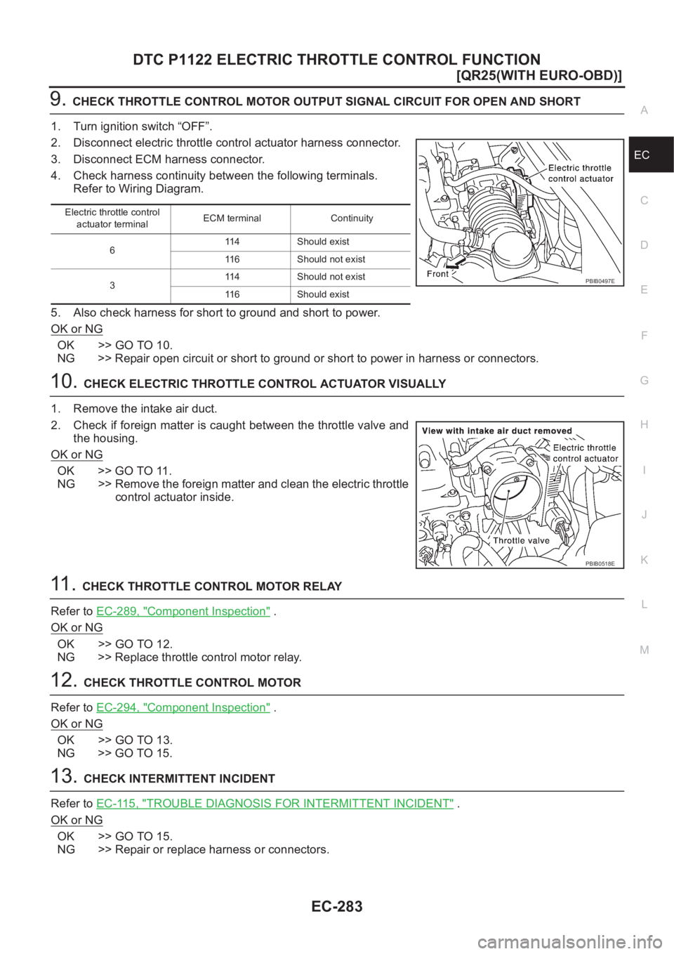
4. Check harness continuity between the following terminals.
Refer to Wiring Diagram.
5. Also check harness for short to ground and short to power.
OK or NG
OK >> GO TO 10.
NG >> Repair open circuit or short to ground or short to power in harness or connectors.
10.CHECK ELECTRIC THROTTLE CONTROL ACTUATOR VISUALLY
1. Remove the intake air duct.
2. Check if foreign matter is caught between the throttle valve and
the housing.
OK or NG
OK >> GO TO 11.
NG >> Remove the foreign matter and clean the electric throttle
control actuator inside.
11 . CHECK THROTTLE CONTROL MOTOR RELAY
Refer to EC-289, "
Component Inspection" .
OK or NG
OK >> GO TO 12.
NG >> Replace throttle control motor relay.
12.CHECK THROTTLE CONTROL MOTOR
Refer to EC-294, "
Component Inspection" .
OK or NG
OK >> GO TO 13.
NG >> GO TO 15.
13.CHECK INTERMITTENT INCIDENT
Refer to EC-115, "
TROUBLE DIAGNOSIS FOR INTERMITTENT INCIDENT" .
OK or NG
OK >> GO TO 15.
NG >> Repair or replace harness or connectors.
Electric throttle control
actuator terminalECM terminal Continuity
6114 Should exist
116 Should not exist
3114 Should not exist
116 Should exist
PBIB0497E
PBIB0518E
Page 635 of 3833
DTC P1124, P1126 THROTTLE CONTROL MOTOR RELAY
EC-285
[QR25(WITH EURO-OBD)]
C
D
E
F
G
H
I
J
K
L
MA
EC
DTC P1124, P1126 THROTTLE CONTROL MOTOR RELAYPFP:16119
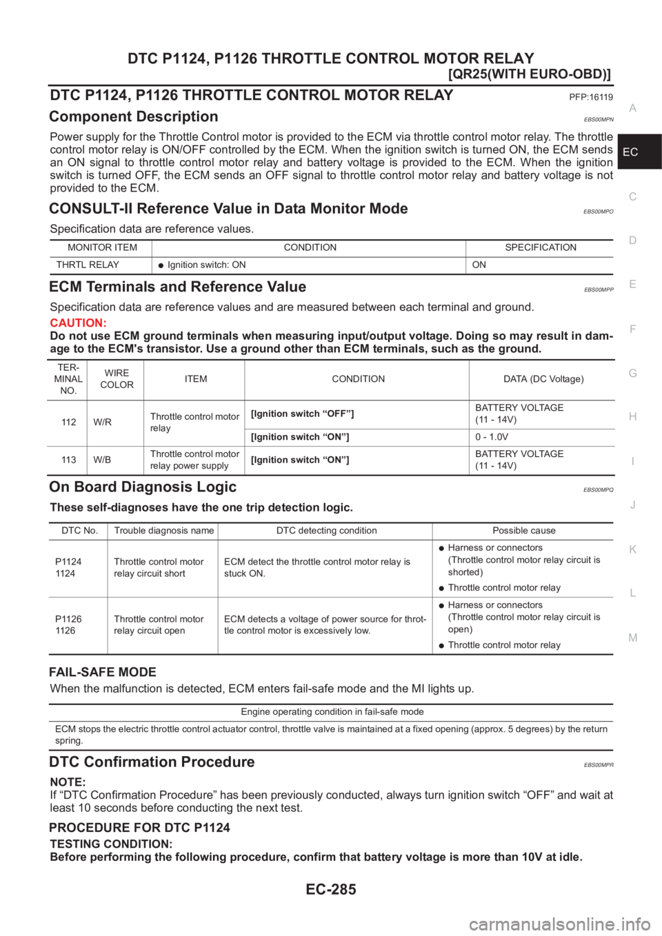
Component DescriptionEBS00MPN
Power supply for the Throttle Control motor is provided to the ECM via throttle control motor relay. The throttle
control motor relay is ON/OFF controlled by the ECM. When the ignition switch is turned ON, the ECM sends
an ON signal to throttle control motor relay and battery voltage is provided to the ECM. When the ignition
switch is turned OFF, the ECM sends an OFF signal to throttle control motor relay and battery voltage is not
provided to the ECM.
CONSULT-II Reference Value in Data Monitor ModeEBS00MPO
Specification data are reference values.
ECM Terminals and Reference ValueEBS00MPP
Specification data are reference values and are measured between each terminal and ground.
CAUTION:
Do not use ECM ground terminals when measuring input/output voltage. Doing so may result in dam-
age to the ECM's transistor. Use a ground other than ECM terminals, such as the ground.
On Board Diagnosis LogicEBS00MPQ
These self-diagnoses have the one trip detection logic.
FAIL-SAFE MODE
When the malfunction is detected, ECM enters fail-safe mode and the MI lights up.
DTC Confirmation ProcedureEBS00MPR
NOTE:
If “DTC Confirmation Procedure” has been previously conducted, always turn ignition switch “OFF” and wait at
least 10 seconds before conducting the next test.
PROCEDURE FOR DTC P1124
TESTING CONDITION:
Before performing the following procedure, confirm that battery voltage is more than 10V at idle.
MONITOR ITEM CONDITION SPECIFICATION
THRTL RELAY
●Ignition switch: ON ON
TER-
MINAL
NO.WIRE
COLORITEM CONDITION DATA (DC Voltage)
11 2 W / RThrottle control motor
relay[Ignition switch “OFF”]BATTERY VOLTAGE
(11 - 14V)
[Ignition switch “ON”]0 - 1.0V
11 3 W / BThrottle control motor
relay power supply[Ignition switch “ON”]BATTERY VOLTAGE
(11 - 14V)
DTC No. Trouble diagnosis name DTC detecting condition Possible cause
P1124
11 2 4Throttle control motor
relay circuit shortECM detect the throttle control motor relay is
stuck ON.
●Harness or connectors
(Throttle control motor relay circuit is
shorted)
●Throttle control motor relay
P1126
11 2 6Throttle control motor
relay circuit openECM detects a voltage of power source for throt-
tle control motor is excessively low.
●Harness or connectors
(Throttle control motor relay circuit is
open)
●Throttle control motor relay
Engine operating condition in fail-safe mode
ECM stops the electric throttle control actuator control, throttle valve is maintained at a fixed opening (approx. 5 degrees) by the return
spring.
Page 636 of 3833
EC-286
[QR25(WITH EURO-OBD)]
DTC P1124, P1126 THROTTLE CONTROL MOTOR RELAY
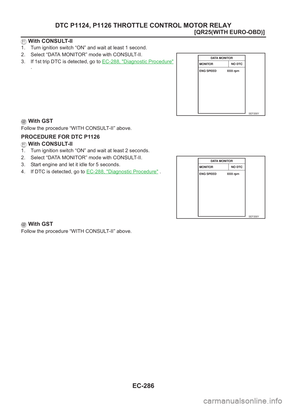
With CONSULT-II
1. Turn ignition switch “ON” and wait at least 1 second.
2. Select “DATA MONITOR” mode with CONSULT-II.
3. If 1st trip DTC is detected, go to EC-288, "
Diagnostic Procedure"
.
With GST
Follow the procedure “WITH CONSULT-II” above.
PROCEDURE FOR DTC P1126
With CONSULT-II
1. Turn ignition switch “ON” and wait at least 2 seconds.
2. Select “DATA MONITOR” mode with CONSULT-II.
3. Start engine and let it idle for 5 seconds.
4. If DTC is detected, go to EC-288, "
Diagnostic Procedure" .
With GST
Follow the procedure “WITH CONSULT-II” above.
SEF058Y
SEF058Y
Page 637 of 3833
DTC P1124, P1126 THROTTLE CONTROL MOTOR RELAY
EC-287
[QR25(WITH EURO-OBD)]
C
D
E
F
G
H
I
J
K
L
MA
EC
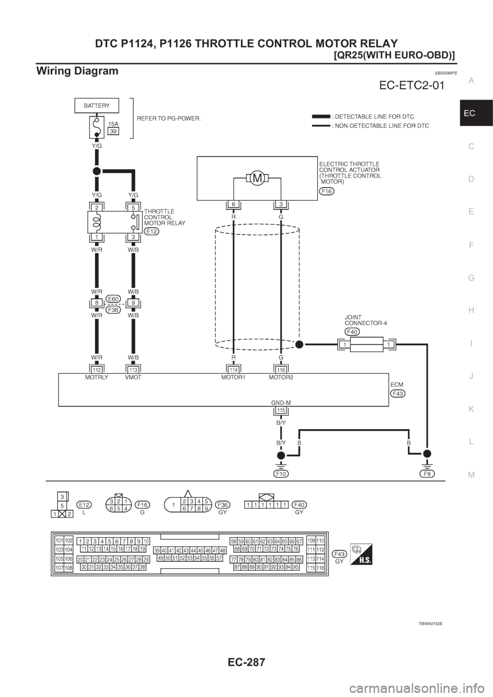
Wiring DiagramEBS00MPS
TBWA0153E
Page 638 of 3833
EC-288
[QR25(WITH EURO-OBD)]
DTC P1124, P1126 THROTTLE CONTROL MOTOR RELAY
Diagnostic Procedure
EBS00MPT
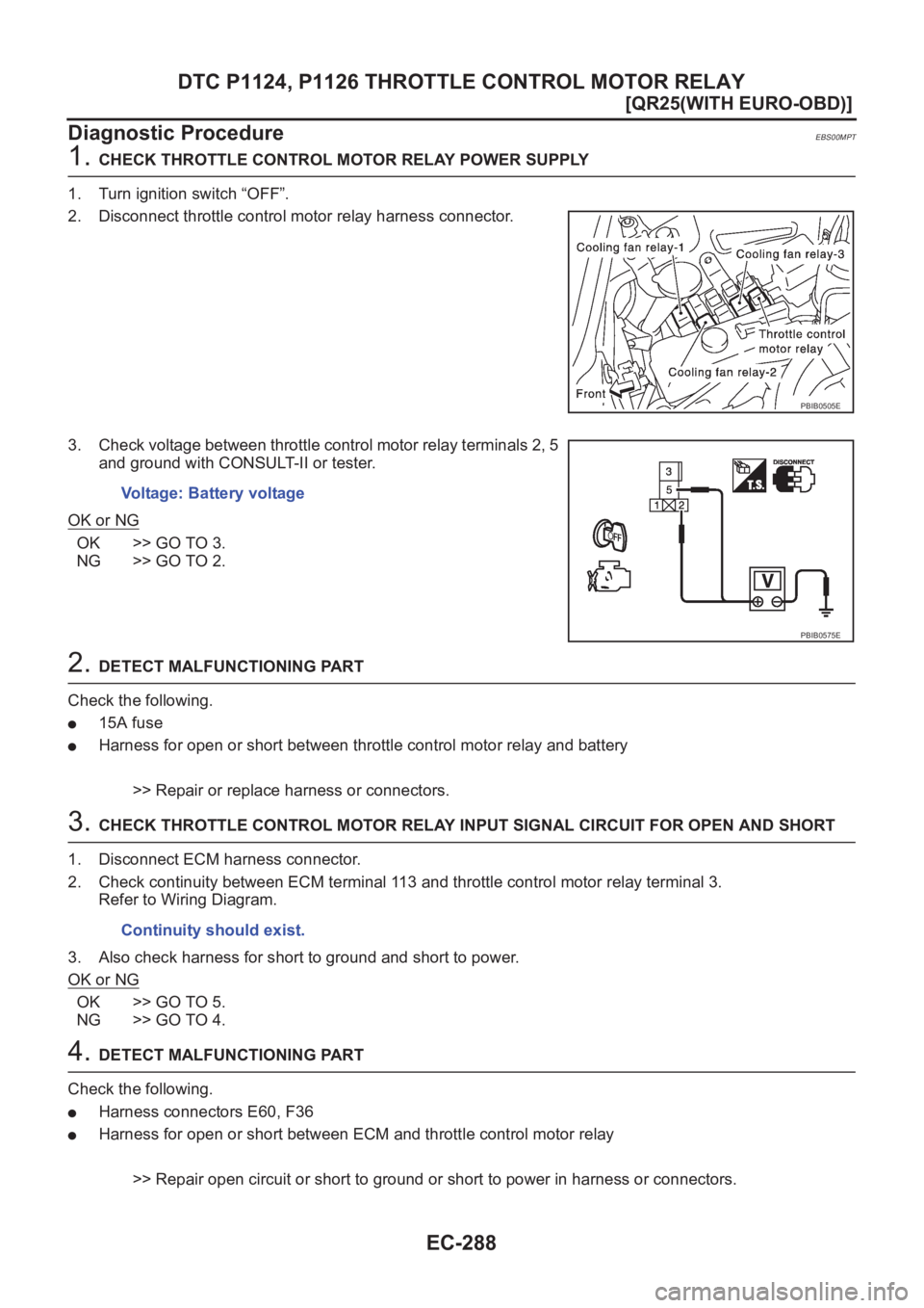
1. CHECK THROTTLE CONTROL MOTOR RELAY POWER SUPPLY
1. Turn ignition switch “OFF”.
2. Disconnect throttle control motor relay harness connector.
3. Check voltage between throttle control motor relay terminals 2, 5
and ground with CONSULT-II or tester.
OK or NG
OK >> GO TO 3.
NG >> GO TO 2.
2. DETECT MALFUNCTIONING PART
Check the following.
●15A fuse
●Harness for open or short between throttle control motor relay and battery
>> Repair or replace harness or connectors.
3. CHECK THROTTLE CONTROL MOTOR RELAY INPUT SIGNAL CIRCUIT FOR OPEN AND SHORT
1. Disconnect ECM harness connector.
2. Check continuity between ECM terminal 113 and throttle control motor relay terminal 3.
Refer to Wiring Diagram.
3. Also check harness for short to ground and short to power.
OK or NG
OK >> GO TO 5.
NG >> GO TO 4.
4. DETECT MALFUNCTIONING PART
Check the following.
●Harness connectors E60, F36
●Harness for open or short between ECM and throttle control motor relay
>> Repair open circuit or short to ground or short to power in harness or connectors.
PBIB0505E
Voltage: Battery voltage
PBIB0575E
Continuity should exist.
Page 639 of 3833
DTC P1124, P1126 THROTTLE CONTROL MOTOR RELAY
EC-289
[QR25(WITH EURO-OBD)]
C
D
E
F
G
H
I
J
K
L
MA
EC
5.CHECK THROTTLE CONTROL MOTOR RELAY OUTPUT SIGNAL CIRCUIT FOR OPEN AND SHORT
1. Check continuity between ECM terminal 112 and throttle control motor relay terminal 1.
Refer to Wiring Diagram.
2. Also check harness for short to ground and short to power.
OK or NG
OK >> GO TO 7.
NG >> GO TO 6.
6.DETECT MALFUNCTIONING PART
Check the following.
●Harness connectors E60, F36
●Harness for open or short between ECM and throttle control motor relay
>> Repair open circuit or short to ground or short to power in harness or connectors.
7.CHECK THROTTLE CONTROL MOTOR RELAY
Refer to EC-289, "
Component Inspection" .
OK or NG
OK >> GO TO 8.
NG >> Replace throttle control motor relay.
8.CHECK INTERMITTENT INCIDENT
Refer to EC-115, "
TROUBLE DIAGNOSIS FOR INTERMITTENT INCIDENT" .
>>INSPECTION END
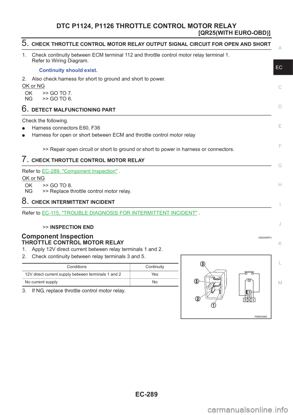
Component InspectionEBS00MPU
THROTTLE CONTROL MOTOR RELAY
1. Apply 12V direct current between relay terminals 1 and 2.
2. Check continuity between relay terminals 3 and 5.
3. If NG, replace throttle control motor relay.Continuity should exist.
Conditions Continuity
12V direct current supply between terminals 1 and 2 Yes
No current supply No
PBIB0098E
Page 673 of 3833
DTC P1217 ENGINE OVER TEMPERATURE
EC-323
[QR25(WITH EURO-OBD)]
C
D
E
F
G
H
I
J
K
L
MA
EC
DTC P1217 ENGINE OVER TEMPERATUREPFP:00000
System DescriptionEBS00M8Z
COOLING FAN CONTROL
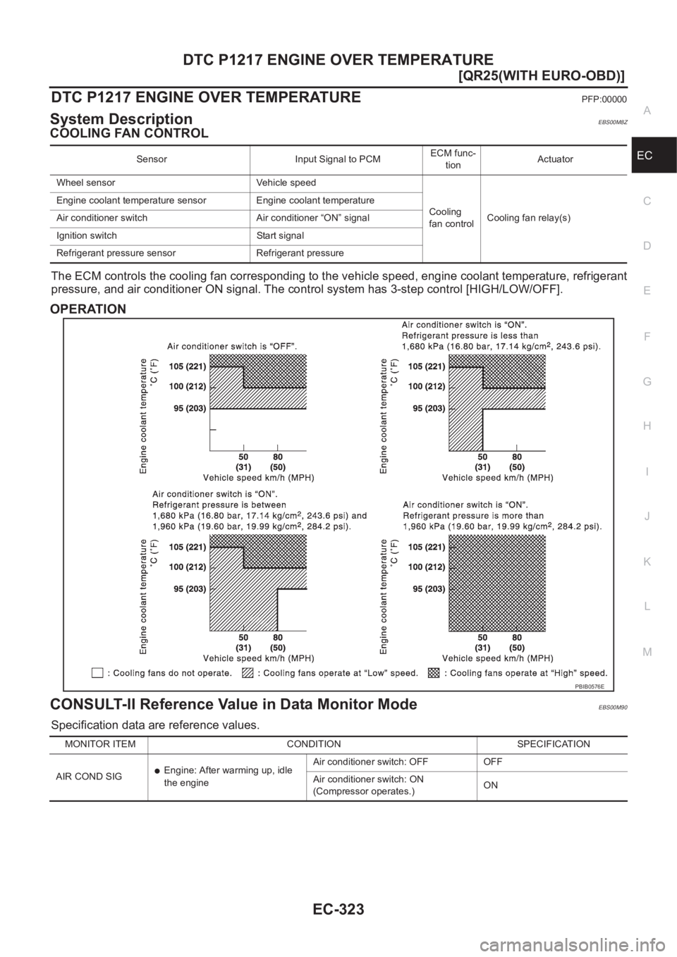
The ECM controls the cooling fan corresponding to the vehicle speed, engine coolant temperature, refrigerant
pressure, and air conditioner ON signal. The control system has 3-step control [HIGH/LOW/OFF].
OPERATION
CONSULT-II Reference Value in Data Monitor ModeEBS00M90
Specification data are reference values.
Sensor Input Signal to PCMECM func-
tionActuator
Wheel sensor Vehicle speed
Cooling
fan controlCooling fan relay(s) Engine coolant temperature sensor Engine coolant temperature
Air conditioner switch Air conditioner “ON” signal
Ignition switch Start signal
Refrigerant pressure sensor Refrigerant pressure
PBIB0576E
MONITOR ITEM CONDITION SPECIFICATION
AIR COND SIG
●Engine: After warming up, idle
the engineAir conditioner switch: OFF OFF
Air conditioner switch: ON
(Compressor operates.)ON