relay NISSAN X-TRAIL 2001 Service Manual PDF
[x] Cancel search | Manufacturer: NISSAN, Model Year: 2001, Model line: X-TRAIL, Model: NISSAN X-TRAIL 2001Pages: 3833, PDF Size: 39.49 MB
Page 814 of 3833
EC-464
[QR25(WITHOUT EURO-OBD)]
TROUBLE DIAGNOSIS
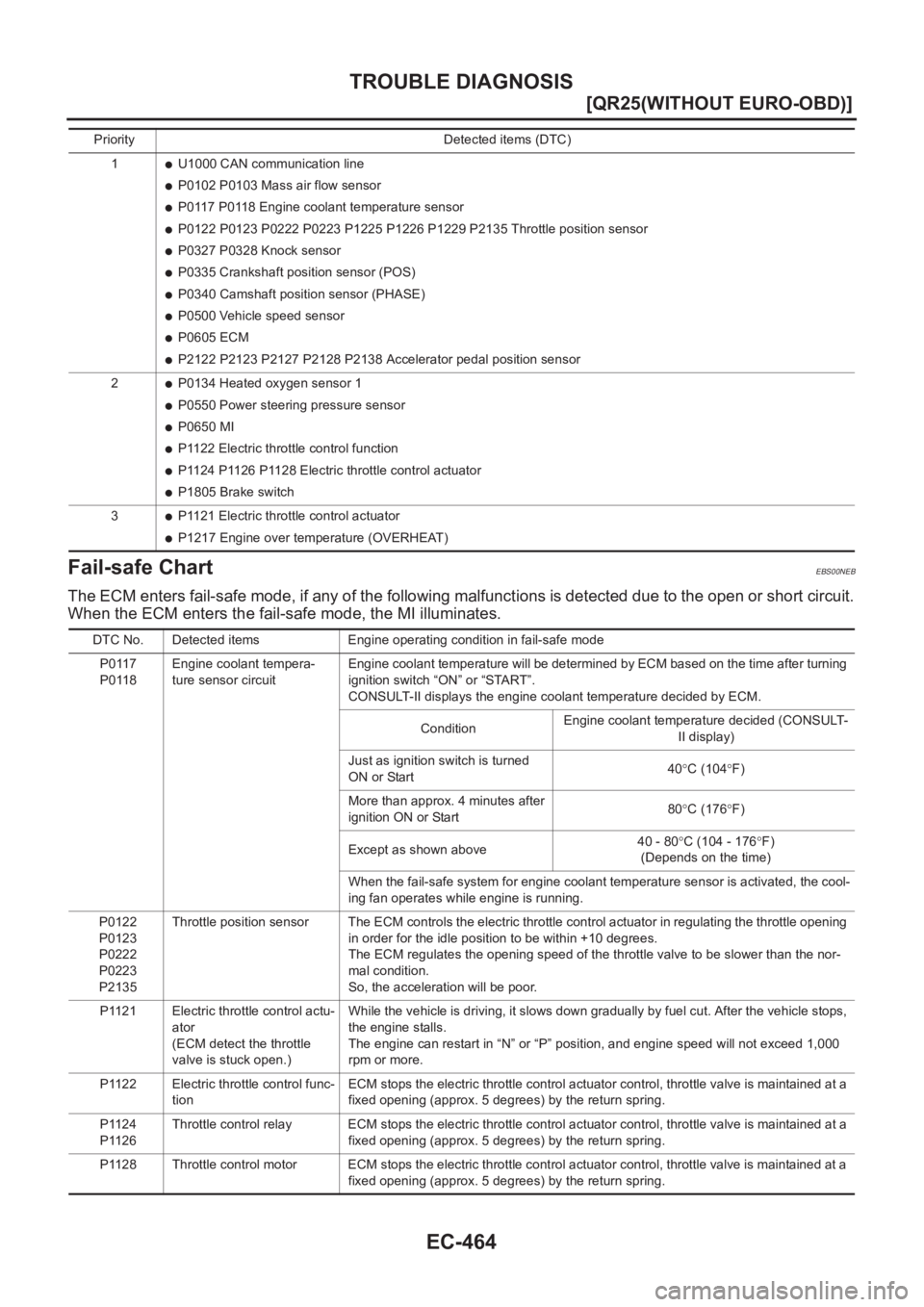
Fail-safe Chart
EBS00NEB
The ECM enters fail-safe mode, if any of the following malfunctions is detected due to the open or short circuit.
When the ECM enters the fail-safe mode, the MI illuminates.
Priority Detected items (DTC)
1
●U1000 CAN communication line
●P0102 P0103 Mass air flow sensor
●P0117 P0118 Engine coolant temperature sensor
●P0122 P0123 P0222 P0223 P1225 P1226 P1229 P2135 Throttle position sensor
●P0327 P0328 Knock sensor
●P0335 Crankshaft position sensor (POS)
●P0340 Camshaft position sensor (PHASE)
●P0500 Vehicle speed sensor
●P0605 ECM
●P2122 P2123 P2127 P2128 P2138 Accelerator pedal position sensor
2
●P0134 Heated oxygen sensor 1
●P0550 Power steering pressure sensor
●P0650 MI
●P1122 Electric throttle control function
●P1124 P1126 P1128 Electric throttle control actuator
●P1805 Brake switch
3
●P1121 Electric throttle control actuator
●P1217 Engine over temperature (OVERHEAT)
DTC No. Detected items Engine operating condition in fail-safe mode
P0117
P0118Engine coolant tempera-
ture sensor circuitEngine coolant temperature will be determined by ECM based on the time after turning
ignition switch “ON” or “START”.
CONSULT-II displays the engine coolant temperature decided by ECM.
ConditionEngine coolant temperature decided (CONSULT-
II display)
Just as ignition switch is turned
ON or Start40°C (104°F)
More than approx. 4 minutes after
ignition ON or Start80°C (176°F)
Except as shown above40 - 80°C (104 - 176°F)
(Depends on the time)
When the fail-safe system for engine coolant temperature sensor is activated, the cool-
ing fan operates while engine is running.
P0122
P0123
P0222
P0223
P2135Throttle position sensor The ECM controls the electric throttle control actuator in regulating the throttle opening
in order for the idle position to be within +10 degrees.
The ECM regulates the opening speed of the throttle valve to be slower than the nor-
mal condition.
So, the acceleration will be poor.
P1121 Electric throttle control actu-
ator
(ECM detect the throttle
valve is stuck open.)While the vehicle is driving, it slows down gradually by fuel cut. After the vehicle stops,
the engine stalls.
The engine can restart in “N” or “P” position, and engine speed will not exceed 1,000
rpm or more.
P1122 Electric throttle control func-
tionECM stops the electric throttle control actuator control, throttle valve is maintained at a
fixed opening (approx. 5 degrees) by the return spring.
P1124
P1126Throttle control relay ECM stops the electric throttle control actuator control, throttle valve is maintained at a
fixed opening (approx. 5 degrees) by the return spring.
P1128 Throttle control motor ECM stops the electric throttle control actuator control, throttle valve is maintained at a
fixed opening (approx. 5 degrees) by the return spring.
Page 830 of 3833
EC-480
[QR25(WITHOUT EURO-OBD)]
TROUBLE DIAGNOSIS
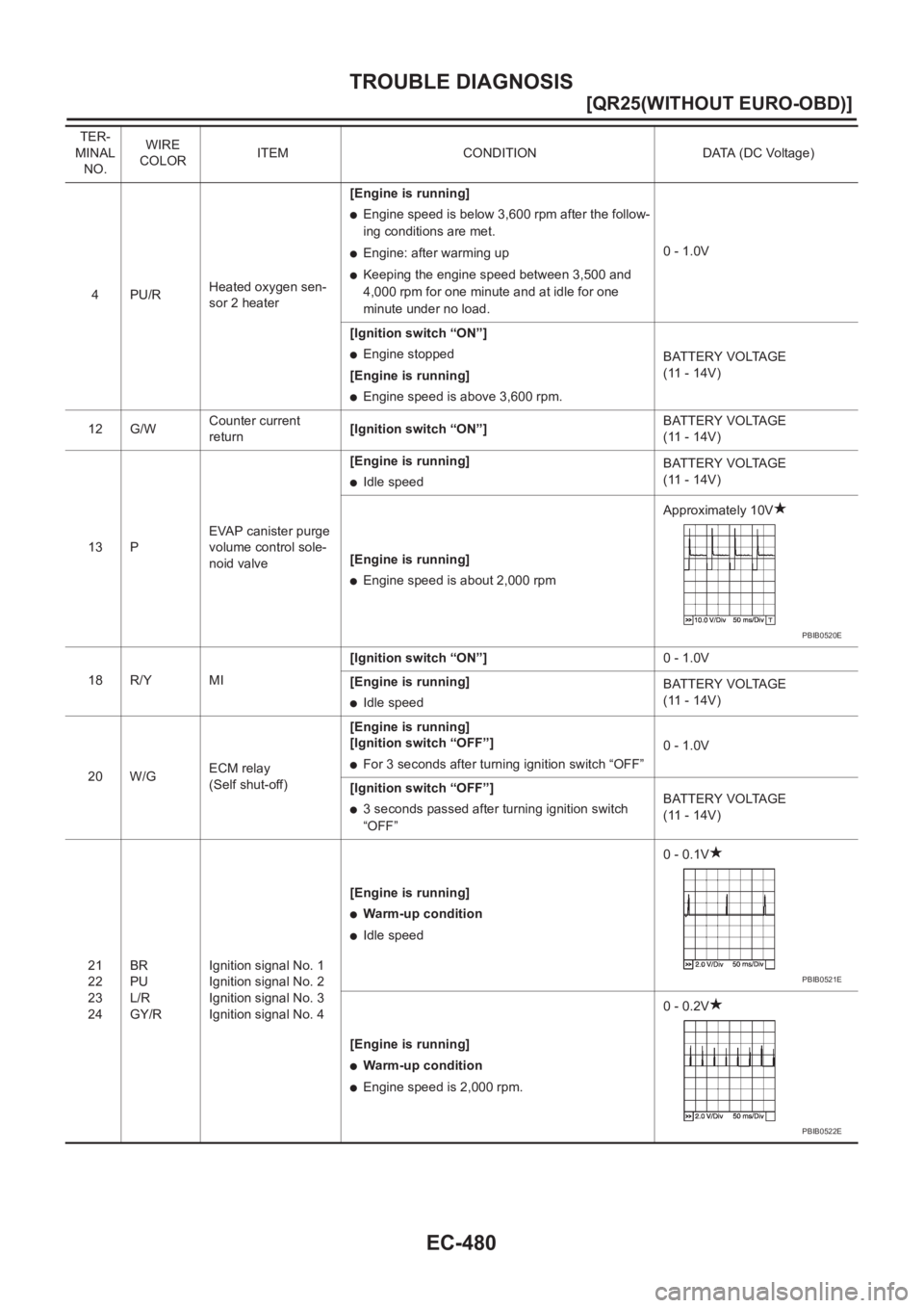
4PU/RHeated oxygen sen-
sor 2 heater[Engine is running]
●Engine speed is below 3,600 rpm after the follow-
ing conditions are met.
●Engine: after warming up
●Keeping the engine speed between 3,500 and
4,000 rpm for one minute and at idle for one
minute under no load.0 - 1.0V
[Ignition switch “ON”]
●Engine stopped
[Engine is running]
●Engine speed is above 3,600 rpm.BATTERY VOLTAGE
(11 - 14V)
12 G/WCounter current
return[Ignition switch “ON”]BATTERY VOLTAGE
(11 - 14V)
13 PEVAP canister purge
volume control sole-
noid valve[Engine is running]
●Idle speedBATTERY VOLTAGE
(11 - 14V)
[Engine is running]
●Engine speed is about 2,000 rpmApproximately 10V
18 R/Y MI[Ignition switch “ON”]0 - 1.0V
[Engine is running]
●Idle speedBATTERY VOLTAGE
(11 - 14V)
20 W/GECM relay
(Self shut-off)[Engine is running]
[Ignition switch “OFF”]
●For 3 seconds after turning ignition switch “OFF”0 - 1.0V
[Ignition switch “OFF”]
●3 seconds passed after turning ignition switch
“OFF”BATTERY VOLTAGE
(11 - 14V)
21
22
23
24BR
PU
L/R
GY/RIgnition signal No. 1
Ignition signal No. 2
Ignition signal No. 3
Ignition signal No. 4[Engine is running]
●Warm-up condition
●Idle speed0 - 0.1V
[Engine is running]
●Warm-up condition
●Engine speed is 2,000 rpm.0 - 0.2V TER-
MINAL
NO.WIRE
COLORITEM CONDITION DATA (DC Voltage)
PBIB0520E
PBIB0521E
PBIB0522E
Page 831 of 3833
TROUBLE DIAGNOSIS
EC-481
[QR25(WITHOUT EURO-OBD)]
C
D
E
F
G
H
I
J
K
L
MA
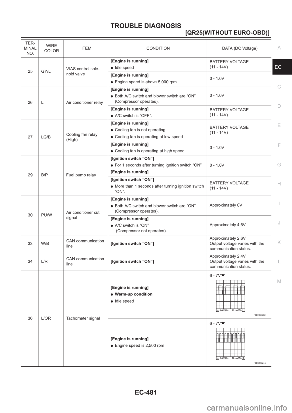
EC25 GY/LVIAS control sole-
noid valve[Engine is running]●Idle speedBATTERY VOLTAGE
(11 - 14V)
[Engine is running]
●Engine speed is above 5,000 rpm0 - 1.0V
26 L Air conditioner relay[Engine is running]
●Both A/C switch and blower switch are “ON”
(Compressor operates).0 - 1.0V
[Engine is running]
●A/C switch is “OFF”.BATTERY VOLTAGE
(11 - 14V)
27 LG/BCooling fan relay
(High)[Engine is running]
●Cooling fan is not operating
●Cooling fan is operating at low speedBATTERY VOLTAGE
(11 - 14V)
[Engine is running]
●Cooling fan is operating at high speed0 - 1.0V
29 B/P Fuel pump relay[Ignition switch “ON”]
●For 1 seconds after turning ignition switch “ON”
[Engine is running]0 - 1.0V
[Ignition switch “ON”]
●More than 1 seconds after turning ignition switch
“ON”.BATTERY VOLTAGE
(11 - 14V)
30 PU/WAir conditioner cut
signal[Engine is running]
●Both A/C switch and blower switch are “ON”
(Compressor operates).Approximately 0V
[Engine is running]
●A/C switch is “ON”
(Compressor not operates).Approximately 4.6V
33 W/BCAN communication
line[Ignition switch “ON”]Approximately 2.6V
Output voltage varies with the
communication status.
34 L/RCAN communication
line[Ignition switch “ON”]Approximately 2.4V
Output voltage varies with the
communication status.
36 L/OR Tachometer signal[Engine is running]
●Warm-up condition
●Idle speed6 - 7V
[Engine is running]
●Engine speed is 2,500 rpm6 - 7V TER-
MINAL
NO.WIRE
COLORITEM CONDITION DATA (DC Voltage)
PBIB0523E
PBIB0524E
Page 832 of 3833
EC-482
[QR25(WITHOUT EURO-OBD)]
TROUBLE DIAGNOSIS
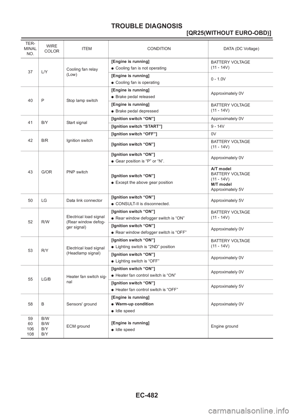
37 L/YCooling fan relay
(Low)[Engine is running]●Cooling fan is not operatingBATTERY VOLTAGE
(11 - 14V)
[Engine is running]
●Cooling fan is operating0 - 1.0V
40 P Stop lamp switch[Engine is running]
●Brake pedal releasedApproximately 0V
[Engine is running]
●Brake pedal depressedBATTERY VOLTAGE
(11 - 14V)
41 B/Y Start signal[Ignition switch “ON”]Approximately 0V
[Ignition switch “START”]9 - 14V
42 B/R Ignition switch[Ignition switch “OFF”]0V
[Ignition switch “ON”]BATTERY VOLTAGE
(11 - 14V)
43 G/OR PNP switch[Ignition switch “ON”]
●Gear position is “P” or “N”.Approximately 0V
[Ignition switch “ON”]
●Except the above gear positionA/T model
BATTERY VOLTAGE
(11 - 14V)
M/T model
Approximately 5V
50 LG Data link connector[Ignition switch “ON”]
●CONSULT-II is disconnected.Approximately 5V
52 R/WElectrical load signal
(Rear window defog-
ger signal)[Ignition switch “ON”]
●Rear window defogger switch is “ON”BATTERY VOLTAGE
(11 - 14V)
[Ignition switch “ON”]
●Rear window defogger switch is “OFF”Approximately 0V
53 R/YElectrical load signal
(Headlamp signal)[Ignition switch “ON”]
●Lighting switch is “2ND” positionBATTERY VOLTAGE
(11 - 14V)
[Ignition switch “ON”]
●Lighting switch is “OFF”Approximately 0V
55 LG/BHeater fan switch sig-
nal[Ignition switch “ON”]
●Heater fan control switch is “ON”Approximately 0V
[Ignition switch “ON”]
●Heater fan control switch is “OFF”Approximately 5V
58 B Sensors' ground[Engine is running]
●Warm-up condition
●Idle speedApproximately 0V
59
60
106
108B/W
B/W
B/Y
B/YECM ground[Engine is running]
●Idle speedEngine ground TER-
MINAL
NO.WIRE
COLORITEM CONDITION DATA (DC Voltage)
Page 836 of 3833
EC-486
[QR25(WITHOUT EURO-OBD)]
TROUBLE DIAGNOSIS
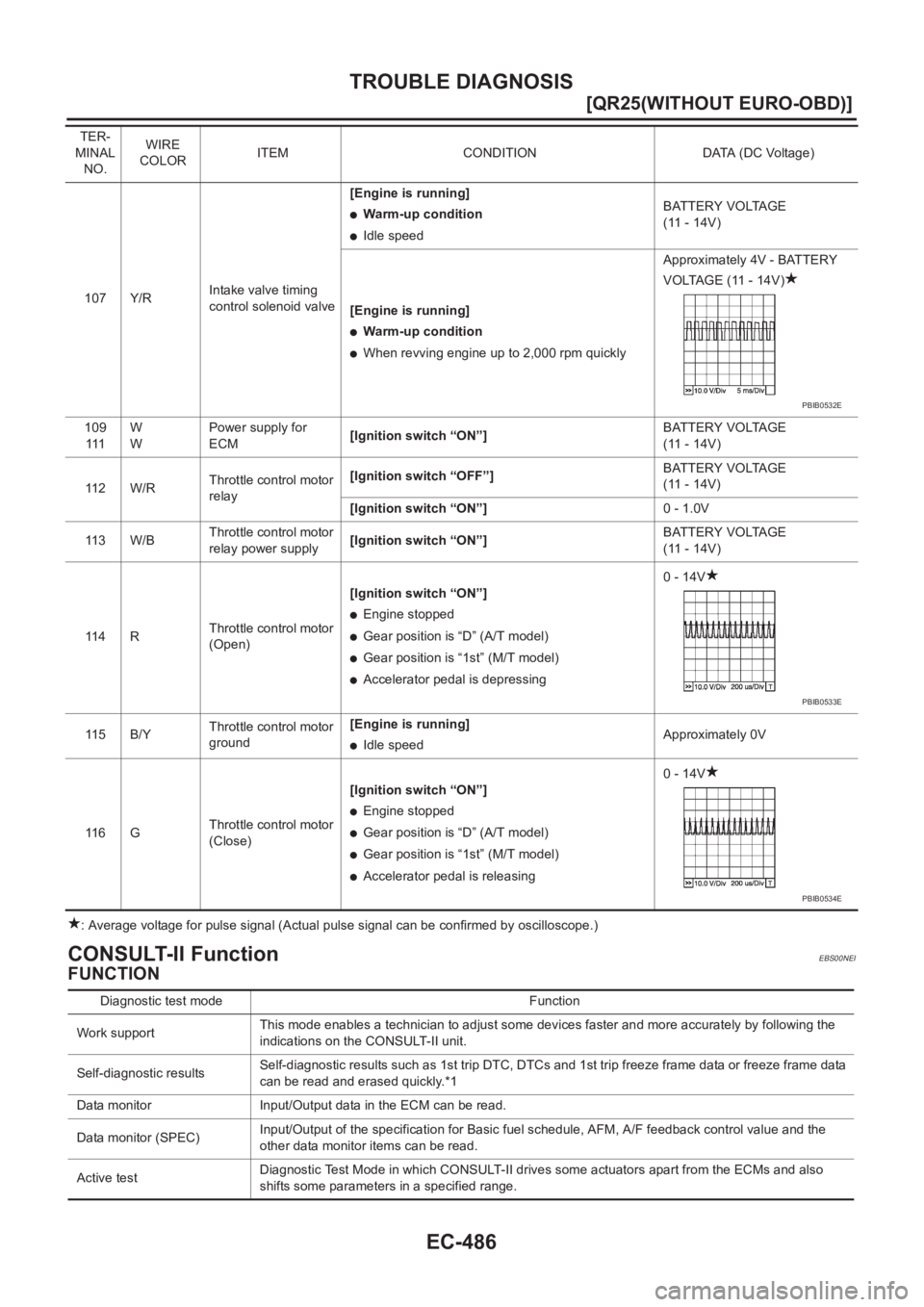
: Average voltage for pulse signal (Actual pulse signal can be confirmed by oscilloscope.)
CONSULT-II FunctionEBS00NEI
FUNCTION
107 Y/RIntake valve timing
control solenoid valve[Engine is running]
●Warm-up condition
●Idle speedBATTERY VOLTAGE
(11 - 14V)
[Engine is running]
●Warm-up condition
●When revving engine up to 2,000 rpm quicklyApproximately 4V - BATTERY
VOLTAGE (11 - 14V)
109
111W
WPower supply for
ECM[Ignition switch “ON”]BATTERY VOLTAGE
(11 - 14V)
11 2 W / RThrottle control motor
relay[Ignition switch “OFF”]BATTERY VOLTAGE
(11 - 14V)
[Ignition switch “ON”]0 - 1.0V
11 3 W / BThrottle control motor
relay power supply[Ignition switch “ON”]BATTERY VOLTAGE
(11 - 14V)
11 4 RThrottle control motor
(Open)[Ignition switch “ON”]
●Engine stopped
●Gear position is “D” (A/T model)
●Gear position is “1st” (M/T model)
●Accelerator pedal is depressing0 - 14V
11 5 B / YThrottle control motor
ground[Engine is running]
●Idle speedApproximately 0V
11 6 GThrottle control motor
(Close)[Ignition switch “ON”]
●Engine stopped
●Gear position is “D” (A/T model)
●Gear position is “1st” (M/T model)
●Accelerator pedal is releasing0 - 14V TER-
MINAL
NO.WIRE
COLORITEM CONDITION DATA (DC Voltage)
PBIB0532E
PBIB0533E
PBIB0534E
Diagnostic test mode Function
Work supportThis mode enables a technician to adjust some devices faster and more accurately by following the
indications on the CONSULT-II unit.
Self-diagnostic resultsSelf-diagnostic results such as 1st trip DTC, DTCs and 1st trip freeze frame data or freeze frame data
can be read and erased quickly.*1
Data monitor Input/Output data in the ECM can be read.
Data monitor (SPEC)Input/Output of the specification for Basic fuel schedule, AFM, A/F feedback control value and the
other data monitor items can be read.
Active testDiagnostic Test Mode in which CONSULT-II drives some actuators apart from the ECMs and also
shifts some parameters in a specified range.
Page 838 of 3833
EC-488
[QR25(WITHOUT EURO-OBD)]
TROUBLE DIAGNOSIS
X: Applicable
*1: This item includes 1st trip DTCs.
*2: This mode includes 1st trip freeze frame data or freeze frame data. The items appear on CONSULT-II screen in freeze frame data
mode only if a 1st trip DTC or DTC is detected. For details, refer to EC-455
.
CONSULT-II INSPECTION PROCEDURE
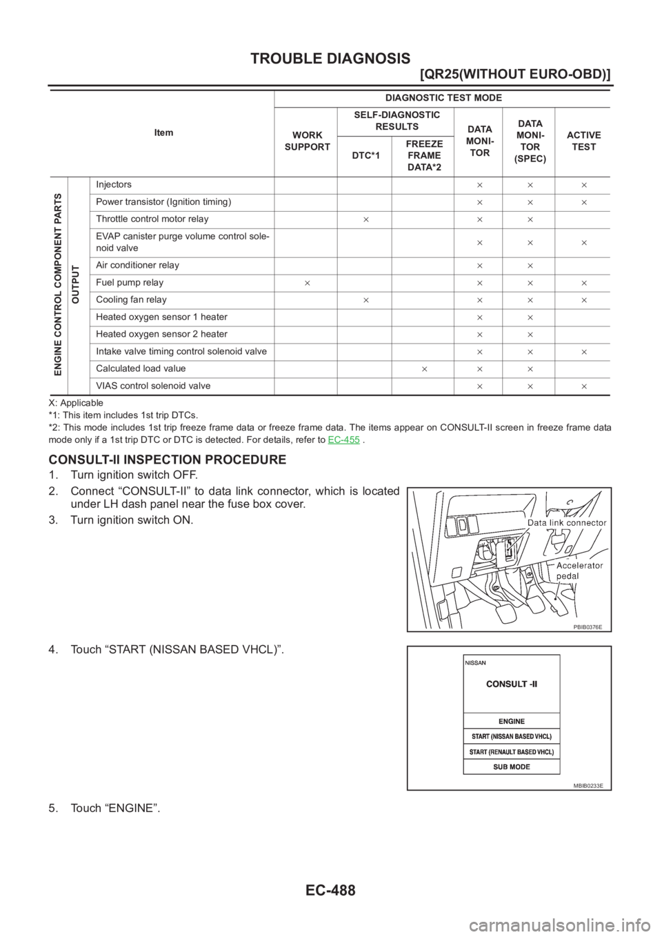
1. Turn ignition switch OFF.
2. Connect “CONSULT-II” to data link connector, which is located
under LH dash panel near the fuse box cover.
3. Turn ignition switch ON.
4. Touch “START (NISSAN BASED VHCL)”.
5. Touch “ENGINE”.
ENGINE CONTROL COMPONENT PARTS
OUTPUT
Injectors×× ×
Power transistor (Ignition timing)×× ×
Throttle control motor relay×××
EVAP canister purge volume control sole-
noid valve×× ×
Air conditioner relay××
Fuel pump relay××××
Cooling fan relay××××
Heated oxygen sensor 1 heater××
Heated oxygen sensor 2 heater××
Intake valve timing control solenoid valve×× ×
Calculated load value×××
VIAS control solenoid valve×× × ItemDIAGNOSTIC TEST MODE
WORK
SUPPORTSELF-DIAGNOSTIC
RESULTS
DATA
MONI-
TORDATA
MONI-
TOR
(SPEC)ACTIVE
TEST
DTC*1FREEZE
FRAME
DATA*2
PBIB0376E
MBIB0233E
Page 842 of 3833
EC-492
[QR25(WITHOUT EURO-OBD)]
TROUBLE DIAGNOSIS
B/FUEL SCHDL
[msec]×
●“Base fuel schedule” indicates the fuel
injection pulse width programmed into
ECM, prior to any learned on board cor-
rection.
IGN TIMING
[BTDC]×
●Indicates the ignition timing computed
by ECM according to the input signals.●When the engine is stopped, a
certain value is indicated.
A/F ALPHA-B1 [%]×
●The mean value of the air-fuel ratio
feedback correction factor per cycle is
indicated.
●When the engine is stopped, a
certain value is indicated.
●This data also includes the data
for the air-fuel ratio learning con-
trol.
CAL/LD VALUE [%]
●“Calculated load value” indicates the
value of the current airflow divided by
peak airflow.
MASS AIRFLOW
[g·m/s]
●Indicates the mass airflow computed by
ECM according to the signal voltage of
the mass air flow sensor.
PURG VOL C/V
[%]
●Indicates the EVAP canister purge vol-
ume control solenoid valve control value
computed by the ECM according to the
input signals.
●The opening becomes larger as the
value increases.
INT/V TIM (B1)
[°CA]
●Indicates [°CA] of intake camshaft
advanced angle.
INT/V SOL (B1) [%]
●The control condition of the intake valve
timing control solenoid valve (deter-
mined by ECM according to the input
signals) is indicated.
ON ... intake valve timing control is oper-
ating.
OFF ... Intake valve timing control is not
operating.
VIAS S/V
[ON/OFF]
●The control condition of the VIAS control
solenoid valve (determined by ECM
according to the input signals) is indi-
cated.
ON ... VIAS control solenoid valve is
operating.
OFF ... VIAS control solenoid valve is
not operating.
AIR COND RLY
[ON/OFF]×
●The air conditioner relay control condi-
tion (determined by ECM according to
the input signals) is indicated.
FUEL PUMP RLY
[ON/OFF]×
●Indicates the fuel pump relay control
condition determined by ECM according
to the input signals.
THRTL RELAY
[ON/OFF]
●Indicates the throttle control motor relay
control condition determined by the
ECM according to the input signals. Monitored item
[Unit]ECM
INPUT
SIG-
NALSMAIN
SIG-
NALSCAN
DIAG
SUP-
PORT
MNTRDescription Remarks
Page 844 of 3833
EC-494
[QR25(WITHOUT EURO-OBD)]
TROUBLE DIAGNOSIS
DATA MONITOR (SPEC) MODE
Monitored Item
NOTE:
●Any monitored item that does not match the vehicle being diagnosed is deleted from the display automatically.
ACTIVE TEST MODE
Test Item
Monitored item [Unit]ECM
input
signalsMain
signalsDescription Remarks
ENG SPEED [rpm]×
●Indicates the engine speed computed
from the signal of the crankshaft position
sensor (POS).
MAS A/F SE-B1 [V]××
●The signal voltage of the mass air flow
sensor specification is displayed.●When engine is running specification
range is indicated.
B/FUEL SCHDL
[msec]
●“Base fuel schedule” indicates the fuel
injection pulse width programmed into
ECM, prior to any learned on board cor-
rection.
●When engine is running specification
range is indicated.
A/F ALPHA-B1 [%]×
●The mean value of the air-fuel ratio feed-
back correction factor per cycle is indi-
cated.●When engine is running specification
range is indicated.
●This data also includes the data for the
air-fuel ratio learning control.
TEST ITEM CONDITION JUDGEMENT CHECK ITEM (REMEDY)
FUEL INJEC-
TION
●Engine: Return to the original
trouble condition
●Change the amount of fuel injec-
tion using CONSULT-II.If trouble symptom disappears, see
CHECK ITEM.
●Harness and connectors
●Fuel injectors
●Heated oxygen sensor 1
IGNITION TIM-
ING
●Engine: Return to the original
trouble condition
●Timing light: Set
●Retard the ignition timing using
CONSULT-II.If trouble symptom disappears, see
CHECK ITEM.
●Perform “Idle Air Volume Learn-
ing”.
POWER BAL-
ANCE
●Engine: After warming up, idle
the engine.
●A/C switch “OFF”
●Shift lever “N”
●Cut off each injector signal one at
a time using CONSULT-II.Engine runs rough or dies.
●Harness and connectors
●Compression
●Fuel injectors
●Power transistor
●Spark plugs
●Ignition coils
COOLING FAN
●Ignition switch: ON
●Turn the cooling fan “ON” and
“OFF” with CONSULT-II.Cooling fan moves and stops.
●Harness and connectors
●Cooling fan relay
●Cooling fan motor
ENG COOLANT
TEMP
●Engine: Return to the original
trouble condition
●Change the engine coolant tem-
perature using CONSULT-II.If trouble symptom disappears, see
CHECK ITEM.
●Harness and connectors
●Engine coolant temperature sen-
sor
●Fuel injectors
FUEL PUMP
RELAY
●Ignition switch: ON (Engine
stopped)
●Turn the fuel pump relay “ON”
and “OFF” using CONSULT-II
and listen to operating sound.Fuel pump relay makes the operat-
ing sound.●Harness and connectors
●Fuel pump relay
Page 848 of 3833
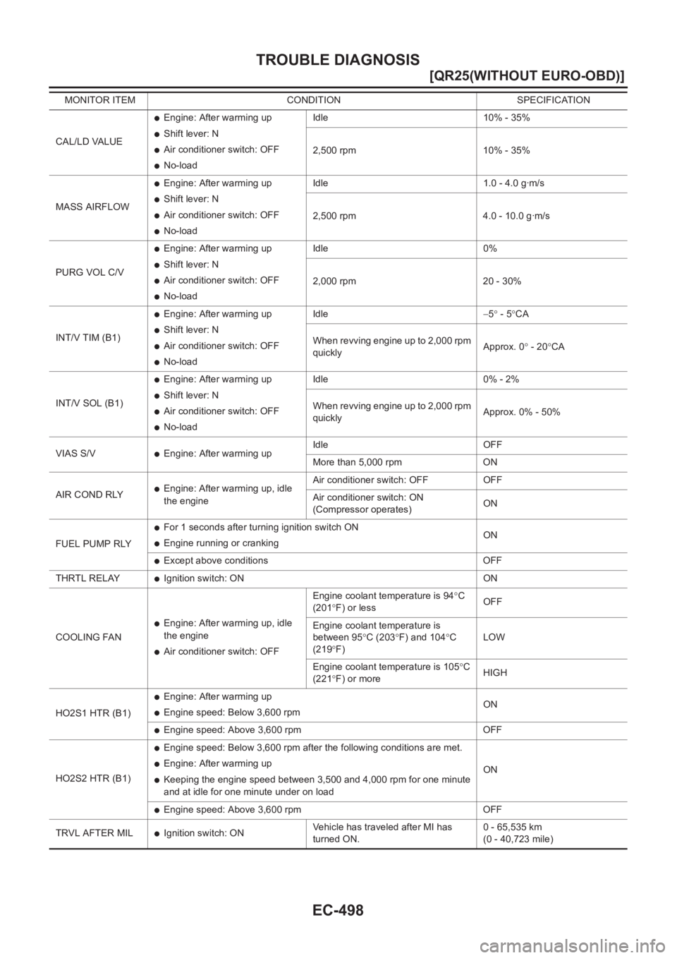
EC-498
[QR25(WITHOUT EURO-OBD)]
TROUBLE DIAGNOSIS
CAL/LD VALUE
●Engine: After warming up
●Shift lever: N
●Air conditioner switch: OFF
●No-loadIdle 10% - 35%
2,500 rpm 10% - 35%
MASS AIRFLOW
●Engine: After warming up
●Shift lever: N
●Air conditioner switch: OFF
●No-loadIdle 1.0 - 4.0 g·m/s
2,500 rpm 4.0 - 10.0 g·m/s
PURG VOL C/V
●Engine: After warming up
●Shift lever: N
●Air conditioner switch: OFF
●No-loadIdle 0%
2,000 rpm 20 - 30%
INT/V TIM (B1)
●Engine: After warming up
●Shift lever: N
●Air conditioner switch: OFF
●No-loadIdle−5° - 5°CA
When revving engine up to 2,000 rpm
quicklyApprox. 0° - 20°CA
INT/V SOL (B1)
●Engine: After warming up
●Shift lever: N
●Air conditioner switch: OFF
●No-loadIdle 0% - 2%
When revving engine up to 2,000 rpm
quicklyApprox. 0% - 50%
VIAS S/V
●Engine: After warming upIdle OFF
More than 5,000 rpm ON
AIR COND RLY
●Engine: After warming up, idle
the engineAir conditioner switch: OFF OFF
Air conditioner switch: ON
(Compressor operates)ON
FUEL PUMP RLY
●For 1 seconds after turning ignition switch ON
●Engine running or crankingON
●Except above conditions OFF
THRTL RELAY
●Ignition switch: ON ON
COOLING FAN
●Engine: After warming up, idle
the engine
●Air conditioner switch: OFFEngine coolant temperature is 94°C
(201°F) or lessOFF
Engine coolant temperature is
between 95°C (203°F) and 104°C
(219°F)LOW
Engine coolant temperature is 105°C
(221°F) or moreHIGH
HO2S1 HTR (B1)
●Engine: After warming up
●Engine speed: Below 3,600 rpmON
●Engine speed: Above 3,600 rpm OFF
HO2S2 HTR (B1)
●Engine speed: Below 3,600 rpm after the following conditions are met.
●Engine: After warming up
●Keeping the engine speed between 3,500 and 4,000 rpm for one minute
and at idle for one minute under on loadON
●Engine speed: Above 3,600 rpm OFF
TRVL AFTER MIL
●Ignition switch: ONVehicle has traveled after MI has
turned ON.0 - 65,535 km
(0 - 40,723 mile) MONITOR ITEM CONDITION SPECIFICATION
Page 858 of 3833
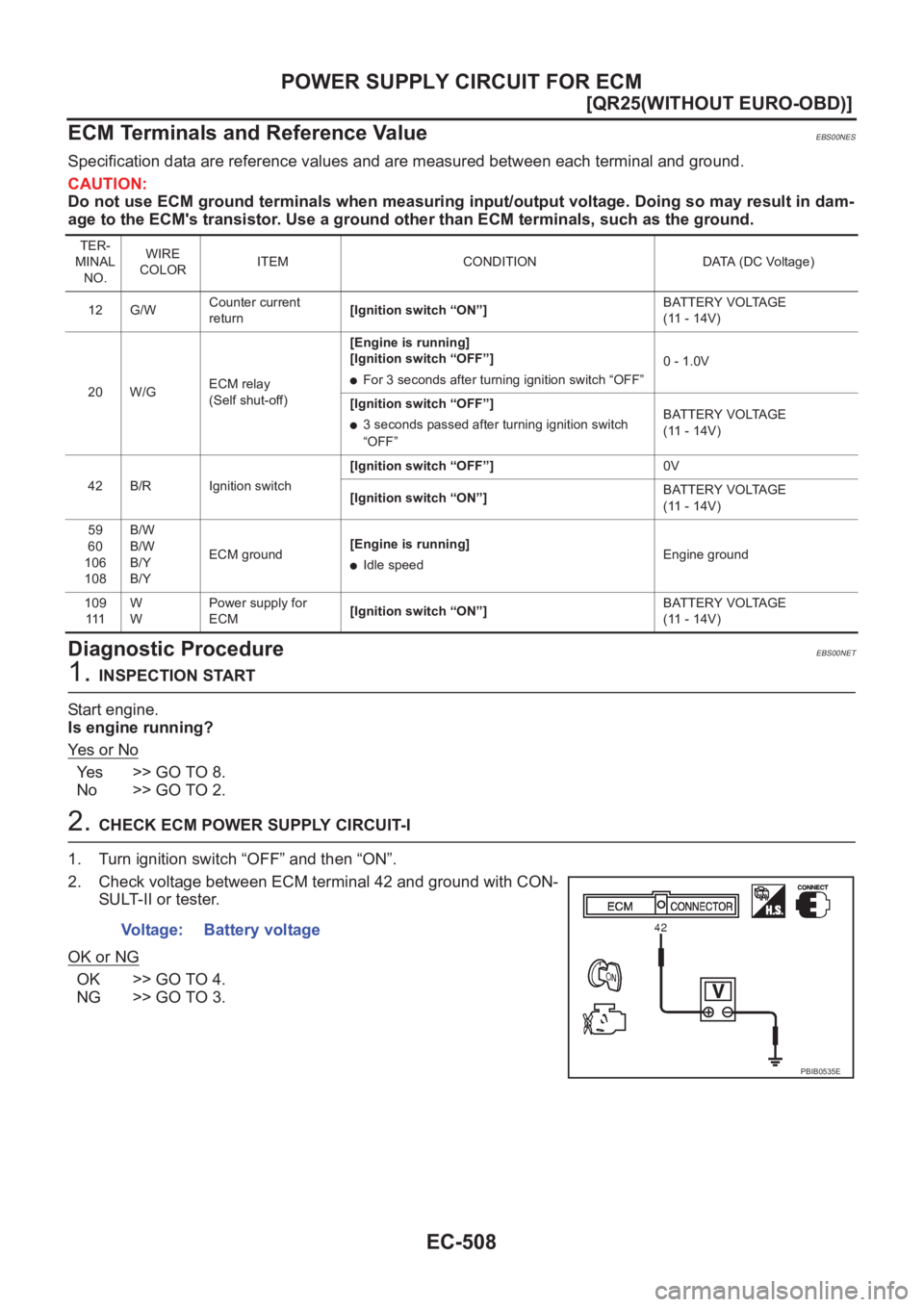
EC-508
[QR25(WITHOUT EURO-OBD)]
POWER SUPPLY CIRCUIT FOR ECM
ECM Terminals and Reference Value
EBS00NES
Specification data are reference values and are measured between each terminal and ground.
CAUTION:
Do not use ECM ground terminals when measuring input/output voltage. Doing so may result in dam-
age to the ECM's transistor. Use a ground other than ECM terminals, such as the ground.
Diagnostic ProcedureEBS00NET
1. INSPECTION START
Start engine.
Is engine running?
Ye s o r N o
Yes >> GO TO 8.
No >> GO TO 2.
2. CHECK ECM POWER SUPPLY CIRCUIT-I
1. Turn ignition switch “OFF” and then “ON”.
2. Check voltage between ECM terminal 42 and ground with CON-
SULT-II or tester.
OK or NG
OK >> GO TO 4.
NG >> GO TO 3.
TER-
MINAL
NO.WIRE
COLORITEM CONDITION DATA (DC Voltage)
12 G/WCounter current
return[Ignition switch “ON”]BATTERY VOLTAGE
(11 - 14V)
20 W/GECM relay
(Self shut-off)[Engine is running]
[Ignition switch “OFF”]
●For 3 seconds after turning ignition switch “OFF”0 - 1.0V
[Ignition switch “OFF”]
●3 seconds passed after turning ignition switch
“OFF”BATTERY VOLTAGE
(11 - 14V)
42 B/R Ignition switch[Ignition switch “OFF”]0V
[Ignition switch “ON”]BATTERY VOLTAGE
(11 - 14V)
59
60
106
108B/W
B/W
B/Y
B/YECM ground[Engine is running]
●Idle speedEngine ground
109
111W
WPower supply for
ECM[Ignition switch “ON”]BATTERY VOLTAGE
(11 - 14V)
Voltage: Battery voltage
PBIB0535E