relay NISSAN X-TRAIL 2001 Service Owner's Manual
[x] Cancel search | Manufacturer: NISSAN, Model Year: 2001, Model line: X-TRAIL, Model: NISSAN X-TRAIL 2001Pages: 3833, PDF Size: 39.49 MB
Page 458 of 3833
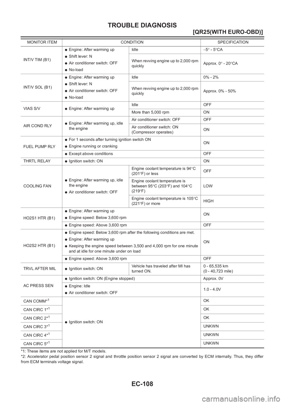
EC-108
[QR25(WITH EURO-OBD)]
TROUBLE DIAGNOSIS
*1: These items are not applied for M/T models.
*2: Accelerator pedal position sensor 2 signal and throttle position sensor 2 signal are converted by ECM internally. Thus, they differ
from ECM terminals voltage signal.INT/V TIM (B1)
●Engine: After warming up
●Shift lever: N
●Air conditioner switch: OFF
●No-loadIdle−5° - 5°CA
When revving engine up to 2,000 rpm
quicklyApprox. 0° - 20°CA
INT/V SOL (B1)
●Engine: After warming up
●Shift lever: N
●Air conditioner switch: OFF
●No-loadIdle 0% - 2%
When revving engine up to 2,000 rpm
quicklyApprox. 0% - 50%
VIAS S/V
●Engine: After warming upIdle OFF
More than 5,000 rpm ON
AIR COND RLY
●Engine: After warming up, idle
the engineAir conditioner switch: OFF OFF
Air conditioner switch: ON
(Compressor operates)ON
FUEL PUMP RLY
●For 1 seconds after turning ignition switch ON
●Engine running or crankingON
●Except above conditions OFF
THRTL RELAY
●Ignition switch: ON ON
COOLING FAN
●Engine: After warming up, idle
the engine
●Air conditioner switch: OFFEngine coolant temperature is 94°C
(201°F) or lessOFF
Engine coolant temperature is
between 95°C (203°F) and 104°C
(219°F)LOW
Engine coolant temperature is 105°C
(221°F) or moreHIGH
HO2S1 HTR (B1)
●Engine: After warming up
●Engine speed: Below 3,600 rpmON
●Engine speed: Above 3,600 rpm OFF
HO2S2 HTR (B1)
●Engine speed: Below 3,600 rpm after the following conditions are met.
●Engine: After warming up
●Keeping the engine speed between 3,500 and 4,000 rpm for one minute
and at idle for one minute under on loadON
●Engine speed: Above 3,600 rpm OFF
TRVL AFTER MIL
●Ignition switch: ONVehicle has traveled after MI has
turned ON.0 - 65,535 km
(0 - 40,723 mile)
AC PRESS SEN
●Ignition switch: ON (Engine stopped) Approx. 0V
●Engine: Idle
●Air conditioner switch: OFF1.0 - 4.0V
CAN COMM*
1
●Ignition switch: ONOK
CAN CIRC 1*
1OK
CAN CIRC 2*
1OK
CAN CIRC 3*
1UNKWN
CAN CIRC 4*
1UNKWN
CAN CIRC 5*
1UNKWN MONITOR ITEM CONDITION SPECIFICATION
Page 467 of 3833
POWER SUPPLY CIRCUIT FOR ECM
EC-117
[QR25(WITH EURO-OBD)]
C
D
E
F
G
H
I
J
K
L
MA
EC
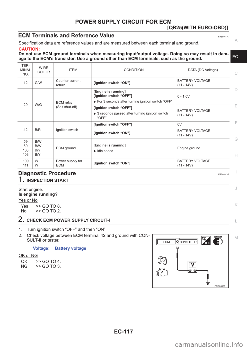
ECM Terminals and Reference ValueEBS00M1C
Specification data are reference values and are measured between each terminal and ground.
CAUTION:
Do not use ECM ground terminals when measuring input/output voltage. Doing so may result in dam-
age to the ECM's transistor. Use a ground other than ECM terminals, such as the ground.
Diagnostic ProcedureEBS00M1D
1.INSPECTION START
Start engine.
Is engine running?
Ye s o r N o
Ye s > > G O T O 8 .
No >> GO TO 2.
2.CHECK ECM POWER SUPPLY CIRCUIT-I
1. Turn ignition switch “OFF” and then “ON”.
2. Check voltage between ECM terminal 42 and ground with CON-
SULT-II or tester.
OK or NG
OK >> GO TO 4.
NG >> GO TO 3.
TER-
MINAL
NO.WIRE
COLORITEM CONDITION DATA (DC Voltage)
12 G/WCounter current
return[Ignition switch “ON”]BATTERY VOLTAGE
(11 - 14V)
20 W/GECM relay
(Self shut-off)[Engine is running]
[Ignition switch “OFF”]
●For 3 seconds after turning ignition switch “OFF”0 - 1.0V
[Ignition switch “OFF”]
●3 seconds passed after turning ignition switch
“OFF”BATTERY VOLTAGE
(11 - 14V)
42 B/R Ignition switch[Ignition switch “OFF”]0V
[Ignition switch “ON”]BATTERY VOLTAGE
(11 - 14V)
59
60
106
108B/W
B/W
B/Y
B/YECM ground[Engine is running]
●Idle speedEngine ground
109
111W
WPower supply for
ECM[Ignition switch “ON”]BATTERY VOLTAGE
(11 - 14V)
Voltage: Battery voltage
PBIB0535E
Page 468 of 3833
EC-118
[QR25(WITH EURO-OBD)]
POWER SUPPLY CIRCUIT FOR ECM
3. DETECT MALFUNCTIONING PART
Check the following.
●Harness connectors M61, F41
●Fuse block (J/B) connector M1
●10A fuse
●Harness for open or short between ECM and fuse
>> Repair harness or connectors.
4. CHECK ECM GROUND CIRCUIT FOR OPEN AND SHORT-I
1. Turn ignition switch “OFF”.
2. Disconnect ECM harness connector.
3. Check harness continuity between ECM terminals 59, 60, 106, 108 and engine ground.
Refer to Wiring Diagram.
4. Also check harness for short to power.
OK or NG
OK >> GO TO 5.
NG >> Repair open circuit or short to power in harness or connectors.
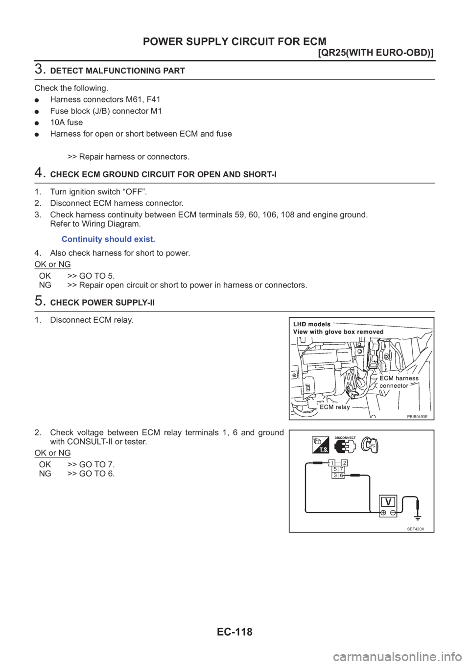
5. CHECK POWER SUPPLY-II
1. Disconnect ECM relay.
2. Check voltage between ECM relay terminals 1, 6 and ground
with CONSULT-II or tester.
OK or NG
OK >> GO TO 7.
NG >> GO TO 6.Continuity should exist.
PBIB0493E
SEF420X
Page 469 of 3833
POWER SUPPLY CIRCUIT FOR ECM
EC-119
[QR25(WITH EURO-OBD)]
C
D
E
F
G
H
I
J
K
L
MA
EC
6.DETECT MALFUNCTIONING PART
Check the following.
●10A fuse
●20A fuse
●Harness connectors E60, F36
●Harness connectors E61, F38
●Harness for open or short between ECM relay and battery
>> Repair open circuit or short to ground or short to power in harness or connectors.
7.CHECK OUTPUT SIGNAL CIRCUIT FOR OPEN AND SHORT
1. Check harness continuity between ECM terminal 20 and ECM relay terminal 2.
Refer to Wiring Diagram.
2. Also check harness for short to ground and short to power.
OK or NG
OK >> Go to EC-379, "IGNITION SIGNAL" .
NG >> Repair open circuit or short to ground or short to power in harness or connectors.
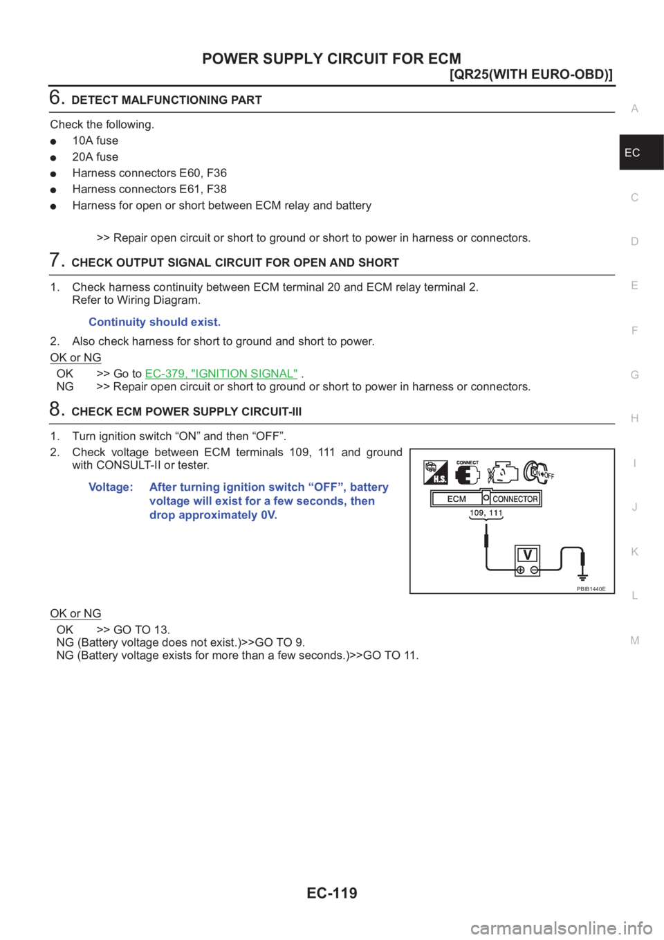
8.CHECK ECM POWER SUPPLY CIRCUIT-III
1. Turn ignition switch “ON” and then “OFF”.
2. Check voltage between ECM terminals 109, 111 and ground
with CONSULT-II or tester.
OK or NG
OK >> GO TO 13.
NG (Battery voltage does not exist.)>>GO TO 9.
NG (Battery voltage exists for more than a few seconds.)>>GO TO 11. Continuity should exist.
Voltage: After turning ignition switch “OFF”, battery
voltage will exist for a few seconds, then
drop approximately 0V.
PBIB1440E
Page 470 of 3833
EC-120
[QR25(WITH EURO-OBD)]
POWER SUPPLY CIRCUIT FOR ECM
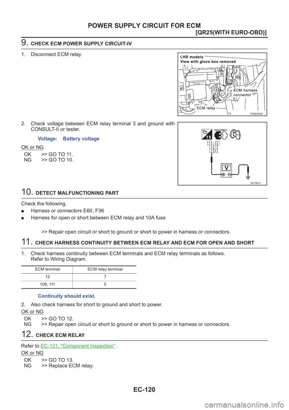
9. CHECK ECM POWER SUPPLY CIRCUIT-IV
1. Disconnect ECM relay.
2. Check voltage between ECM relay terminal 3 and ground with
CONSULT-II or tester.
OK or NG
OK >> GO TO 11.
NG >> GO TO 10.
10. DETECT MALFUNCTIONING PART
Check the following.
●Harness or connectors E60, F36
●Harness for open or short between ECM relay and 10A fuse
>> Repair open circuit or short to ground or short to power in harness or connectors.
11 . CHECK HARNESS CONTINUITY BETWEEN ECM RELAY AND ECM FOR OPEN AND SHORT
1. Check harness continuity between ECM terminals and ECM relay terminals as follows.
Refer to Wiring Diagram.
2. Also check harness for short to ground and short to power.
OK or NG
OK >> GO TO 12.
NG >> Repair open circuit or short to ground or short to power in harness or connectors.
12. CHECK ECM RELAY
Refer to EC-121, "
Component Inspection" .
OK or NG
OK >> GO TO 13.
NG >> Replace ECM relay.
PBIB0493E
Voltage: Battery voltage
SEF860T
ECM terminal ECM relay terminal
12 7
109, 111 5
Continuity should exist.
Page 471 of 3833
POWER SUPPLY CIRCUIT FOR ECM
EC-121
[QR25(WITH EURO-OBD)]
C
D
E
F
G
H
I
J
K
L
MA
EC
13.CHECK ECM GROUND CIRCUIT FOR OPEN AND SHORT-II
1. Turn ignition switch “OFF”.
2. Disconnect ECM harness connector.
3. Check harness continuity between ECM terminals 59, 60, 106, 108 and engine ground.
Refer to Wiring Diagram.
4. Also check harness for short to power.
OK or NG
OK >> GO TO 14.
NG >> Repair open circuit or short to power in harness or connectors.
14.CHECK INTERMITTENT INCIDENT
Refer to EC-115, "
TROUBLE DIAGNOSIS FOR INTERMITTENT INCIDENT" .
>>INSPECTION END
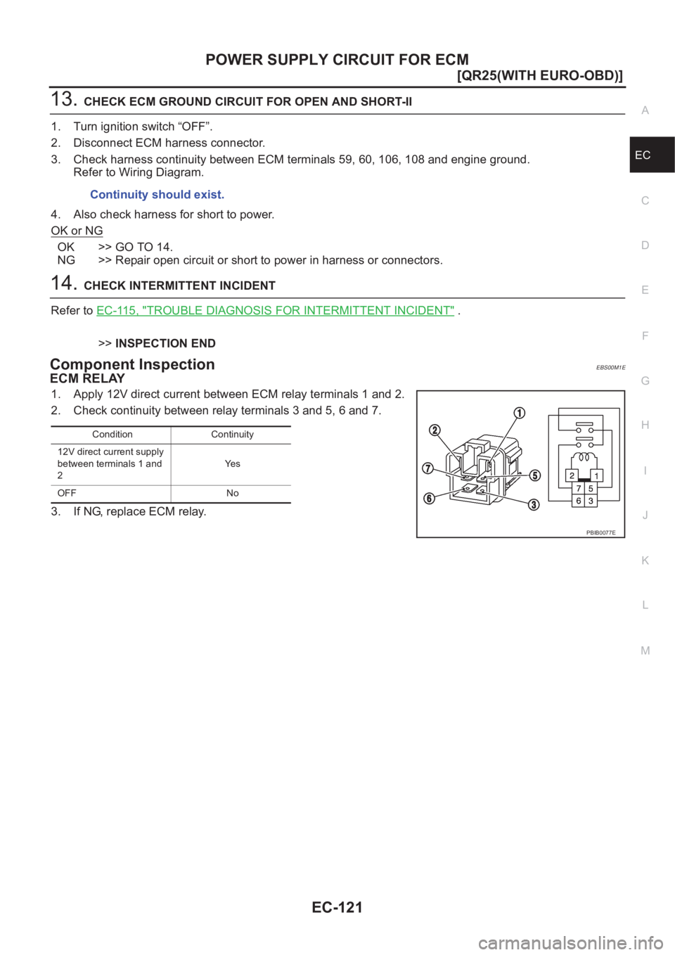
Component InspectionEBS00M1E
ECM RELAY
1. Apply 12V direct current between ECM relay terminals 1 and 2.
2. Check continuity between relay terminals 3 and 5, 6 and 7.
3. If NG, replace ECM relay.Continuity should exist.
Condition Continuity
12V direct current supply
between terminals 1 and
2Ye s
OFF No
PBIB0077E
Page 492 of 3833
EC-142
[QR25(WITH EURO-OBD)]
DTC P0102, P0103 MAF SENSOR
5. DETECT MALFUNCTIONING PART
Check the following.
●Harness for open or short between ECM relay and mass air flow sensor
●Harness for open or short between mass air flow sensor and ECM
>> Repair harness or connectors.
6. CHECK MAF SENSOR GROUND CIRCUIT FOR OPEN AND SHORT
1. Turn ignition switch “OFF”.
2. Disconnect ECM harness connector.
3. Check harness continuity between MAF sensor terminal 3 and ECM terminal 80.
Refer to Wiring Diagram.
4. Also check harness for short to ground and short to power.
OK or NG
OK >> GO TO 7.
NG >> Repair open circuit or short to ground or short to power in harness or connectors.
7. CHECK MAF SENSOR INPUT SIGNAL CIRCUIT FOR OPEN AND SHORT
1. Check harness continuity between MAF sensor terminal 1 and ECM terminal 72.
Refer to Wiring Diagram.
2. Also check harness for short to ground and short to power.
OK or NG
OK >> GO TO 8.
NG >> Repair open circuit or short to ground or short to power in harness or connectors.
8. CHECK MASS AIR FLOW SENSOR
Refer to EC-142, "
Component Inspection" .
OK or NG
OK >> GO TO 9.
NG >> Replace mass air flow sensor.
9. CHECK INTERMITTENT INCIDENT
Refer to EC-115, "
TROUBLE DIAGNOSIS FOR INTERMITTENT INCIDENT" .
>>INSPECTION END
Component InspectionEBS00M2F
MASS AIR FLOW SENSOR
1. Reconnect harness connectors disconnected.
2. Start engine and warm it up to normal operating temperature.Continuity should exist.
Continuity should exist.
Page 580 of 3833
EC-230
[QR25(WITH EURO-OBD)]
DTC P0335 CKP SENSOR (POS)
Diagnostic Procedure
EBS00M5J
1. RETIGHTEN GROUND SCREWS
1. Turn ignition switch “OFF”.
2. Loosen and retighten engine ground screws.
>> GO TO 2.
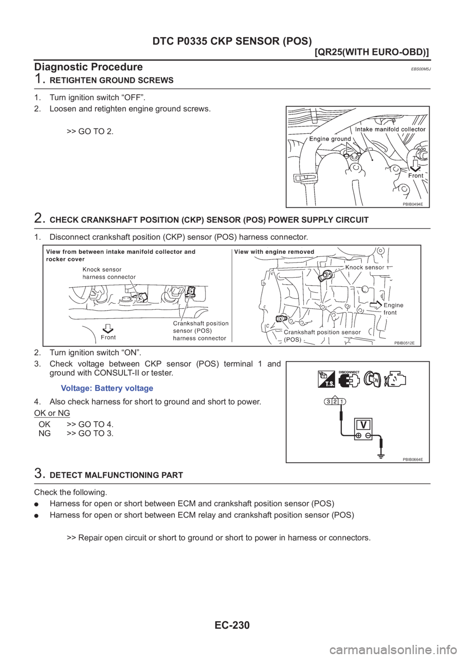
2. CHECK CRANKSHAFT POSITION (CKP) SENSOR (POS) POWER SUPPLY CIRCUIT
1. Disconnect crankshaft position (CKP) sensor (POS) harness connector.
2. Turn ignition switch “ON”.
3. Check voltage between CKP sensor (POS) terminal 1 and
ground with CONSULT-II or tester.
4. Also check harness for short to ground and short to power.
OK or NG
OK >> GO TO 4.
NG >> GO TO 3.
3. DETECT MALFUNCTIONING PART
Check the following.
●Harness for open or short between ECM and crankshaft position sensor (POS)
●Harness for open or short between ECM relay and crankshaft position sensor (POS)
>> Repair open circuit or short to ground or short to power in harness or connectors.
PBIB0494E
Voltage: Battery voltage
PBIB0512E
PBIB0664E
Page 587 of 3833
DTC P0340 CMP SENSOR (PHASE)
EC-237
[QR25(WITH EURO-OBD)]
C
D
E
F
G
H
I
J
K
L
MA
EC
4.DETECT MALFUNCTIONING PART
Check the following.
●Harness for open or short between ECM and camshaft position sensor (PHASE)
●Harness for open or short between ECM relay and camshaft position sensor (PHASE)
>> Repair open circuit or short to ground or short to power in harness or connectors.
5.CHECK CMP SENSOR (PHASE) GROUND CIRCUIT FOR OPEN AND SHORT
1. Turn ignition switch “OFF”.
2. Check harness continuity between CMP sensor (PHASE) terminal 3 and engine ground.
3. Also check harness for short to power.
OK or NG
OK >> GO TO 6.
NG >> Repair open circuit or short to power in harness or connectors.
6.CHECK CMP SENSOR (PHASE) INPUT SIGNAL CIRCUIT FOR OPEN AND SHORT
1. Disconnect ECM harness connector.
2. Check harness continuity between ECM terminal 63 and CMP sensor (PHASE) terminal 2.
Refer to Wiring Diagram.
3. Also check harness for short to ground or short to power.
OK or NG
OK >> GO TO 7.
NG >> Repair open circuit or short to ground or short to power in harness or connectors.
7.CHECK CAMSHAFT POSITION SENSOR (PHASE)
Refer to EC-238, "
Component Inspection" .
OK or NG
OK >> GO TO 8.
NG >> Replace camshaft position sensor (PHASE).
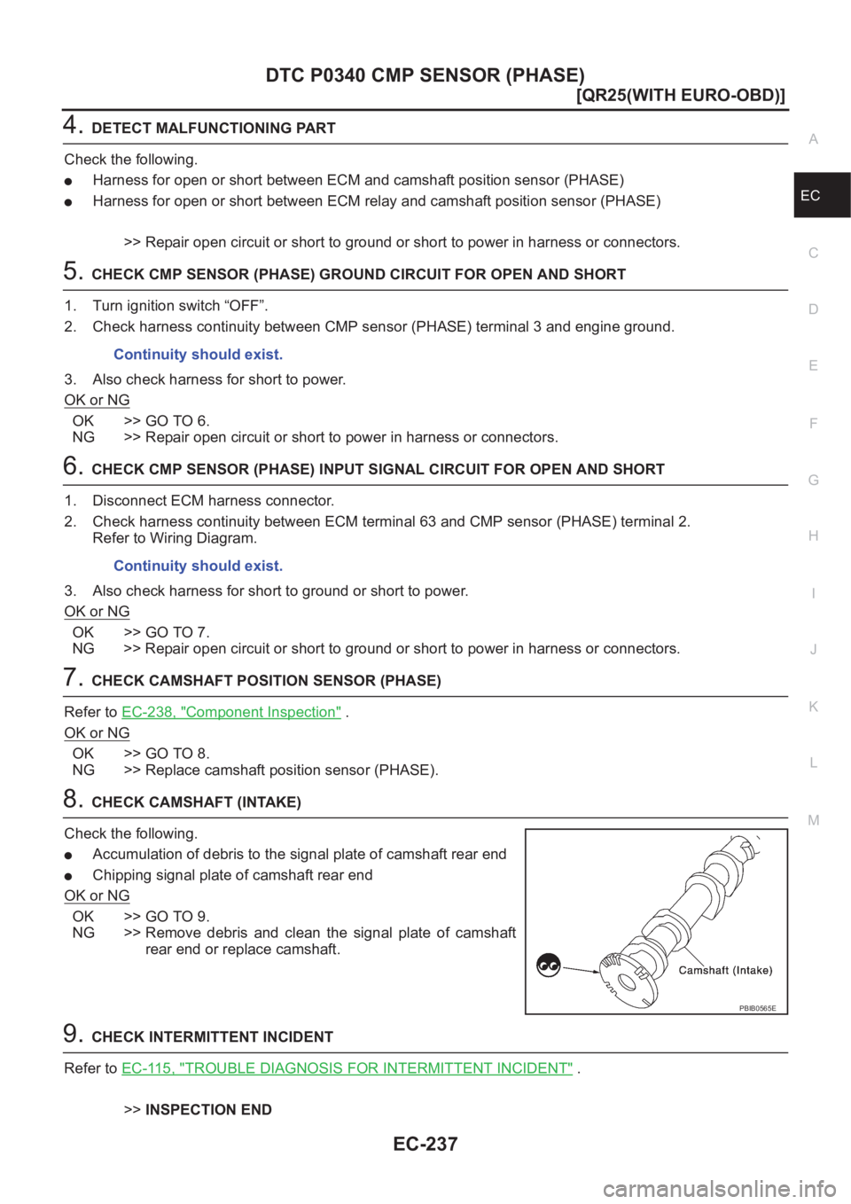
8.CHECK CAMSHAFT (INTAKE)
Check the following.
●Accumulation of debris to the signal plate of camshaft rear end
●Chipping signal plate of camshaft rear end
OK or NG
OK >> GO TO 9.
NG >> Remove debris and clean the signal plate of camshaft
rear end or replace camshaft.
9.CHECK INTERMITTENT INCIDENT
Refer to EC-115, "
TROUBLE DIAGNOSIS FOR INTERMITTENT INCIDENT" .
>>INSPECTION END Continuity should exist.
Continuity should exist.
PBIB0565E
Page 624 of 3833
EC-274
[QR25(WITH EURO-OBD)]
DTC P1111 IVT CONTROL SOLENOID VALVE
Diagnostic Procedure
EBS00M76
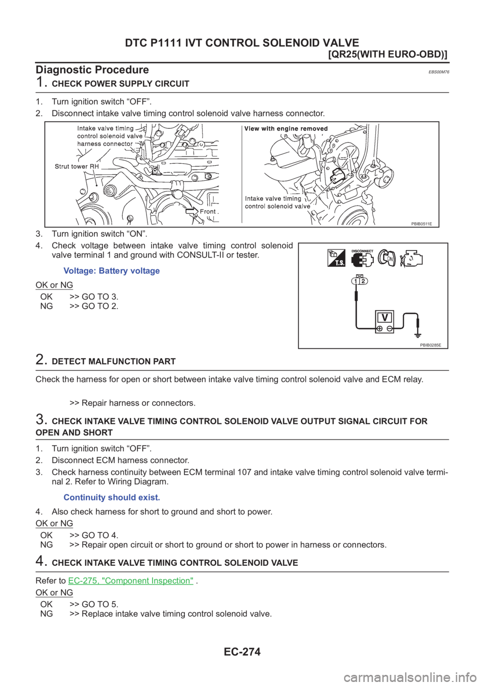
1. CHECK POWER SUPPLY CIRCUIT
1. Turn ignition switch “OFF”.
2. Disconnect intake valve timing control solenoid valve harness connector.
3. Turn ignition switch “ON”.
4. Check voltage between intake valve timing control solenoid
valve terminal 1 and ground with CONSULT-II or tester.
OK or NG
OK >> GO TO 3.
NG >> GO TO 2.
2. DETECT MALFUNCTION PART
Check the harness for open or short between intake valve timing control solenoid valve and ECM relay.
>> Repair harness or connectors.
3. CHECK INTAKE VALVE TIMING CONTROL SOLENOID VALVE OUTPUT SIGNAL CIRCUIT FOR
OPEN AND SHORT
1. Turn ignition switch “OFF”.
2. Disconnect ECM harness connector.
3. Check harness continuity between ECM terminal 107 and intake valve timing control solenoid valve termi-
nal 2. Refer to Wiring Diagram.
4. Also check harness for short to ground and short to power.
OK or NG
OK >> GO TO 4.
NG >> Repair open circuit or short to ground or short to power in harness or connectors.
4. CHECK INTAKE VALVE TIMING CONTROL SOLENOID VALVE
Refer to EC-275, "
Component Inspection" .
OK or NG
OK >> GO TO 5.
NG >> Replace intake valve timing control solenoid valve.Voltage: Battery voltage
PBIB0511E
PBIB0285E
Continuity should exist.