ECO mode NISSAN X-TRAIL 2001 Service Repair Manual
[x] Cancel search | Manufacturer: NISSAN, Model Year: 2001, Model line: X-TRAIL, Model: NISSAN X-TRAIL 2001Pages: 3833, PDF Size: 39.49 MB
Page 2826 of 3833
BRC-42
[4WD/ABS]
TROUBLE DIAGNOSIS
Using active test mode of CONSULT-II, supply current to the 4WD solenoid valve and check that the mon-
itor current becomes close to this supply current.
●The 4WDcontrol unit is normal when the difference between 4WD solenoid valve current and the monitor
current is within ±10%.
It is necessary to inspect the electronically controlled coupling assembly.
TIGHT-CORNER BRAKING SYMPTOM OCCURS WHEN THE VEHICLE IS STARTED IN AUTO
WARNING LAMP REMAIN OFF).
1. THROTTLE POSITION SENSOR AND HARNESS INSPECTION
Check accelerator pedal stroke.
OK or NG
OK >> Perform self-diagnosis again.
NG >> Malfunctioning throttle position sensor harness
4WD ACTUATOR RELAY (4WD SOLENOID ACTUATOR RELAY) TURNS ON/OFF FREQUENTLY
1. SELF-DIAGNOSIS RESULT IS 4WD ACTUATOR RELAY (4WD SOLENOID ACTUATOR RELAY) ON
ERROR AND OFF ERROR
Is self-diagnosis result [ON error and OFF error]?
OK or NG
OK >> GO TO 2.
NG >> Repair or replace as necessary.
2. 4WD ACTUATOR RELAY (4WD SOLENOID ACTUATOR RELAY) AND HARNESS INSPECTION
Is self-diagnosis result [ON error and OFF error]?
OK or NG
OK >> Perform self-diagnosis again.
NG >> Malfunctioning 4WD actuator relay (4WD solenoid actuator relay) harness
ABS Warning Lamp Does Not Illuminate. (ABS Warning Lamp Does Not Come
On When The Ignition Switch Is Turned ON.)
EFS001BP
●Replace the combination meter control unit.
ABS Warning Lamp Illuminates With Ignition ON, But Does Not Illuminates After
A Few Seconds. (ABS Warning Lamp Has Illuminated.)
EFS001BQ
1. 4WD/ABS CONTROL MODULE CONNECTOR CONNECTION INSPECTION
●Remove glove box on the passenger side and check 4WD/ABS control module connector for proper con-
nection.
Is inspection result OK?
YES >> Proceed to 2. (4WD/ABS control unit connector is properly connected.)
NO >>
●Connect the 4WD/ABS control unit connector and perform inspection again.
2. USING CONSULT, PERFORM SELF-DIAGNOSIS
●Connect the CONSULT-II and perform self-diagnosis.
Is inspection result OK?
YES >> GO TO 3. (No self-diagnosis malfunction indicated.)
NO >> Perform inspection according to the trouble codes displayed on the CONSULT-II. Refer to the
“DTC chart”. Example) Monitor value becomes Approx. 1 A for 4WD solenoid current 1 A setting.
Page 2827 of 3833
TROUBLE DIAGNOSIS
BRC-43
[4WD/ABS]
C
D
E
G
H
I
J
K
L
MA
B
BRC
3.CHECK CONTINUITY BETWEEN IGNITION SWITCH AND ABS WARNING LAMP
●Disconnect 4WD/ABS control unit connector.
●Check continuity between ignition switch and 4WD/ABS control module terminal No. 4. (Open circuit
check)
Is inspection result OK?
YES >> Continuity exists. Connect 4WD/ABS control module connector, check again.
NO >> Continuity does not exist. Check ABS warning lamp path.
4.CHECK FUSE
●Check if Fuse No.8 is working normally.
Is the check result OK?
YES >> Repair or replace the harness in between 4WD/ABS control unit and IGN.
NO >> Replace the fuse and replace again.
●If the figure of the monitor is with in ± 10% of the set value of E-TS solenoid electric current, 4WD/ABS C/
U is operating normally. Check for electric control coupling ASSY is required.
4WD Warning Lamp Does Not Illuminate With Ignition ON.EFS001BR
1.INSPECTION OF BLOWN 4WD WARNING LAMP BULB
●Remove glove box on the passenger side and disconnect the 4WD/ABS control unit connector.
●Confirm continuity between 4WD/ABS control unit connector terminals No. 3 (IGN) and No. 4 (ABS warn-
ing lamp).
Is inspection result OK?
YES >> GO TO 3. (Continuity exists.)
NO >>
●Check 4WD warning lamp harness.
●Remove meter control module assembly and check for blown 4WD warning lamp bulb.
2.4WD ACTUATOR RELAY HARNESS INSPECTION
●Open the hood and check that the 4WD relay is properly installed in the relay box.
●Confirm continuity between 4WD/ABS control unit connector terminals No. 7 (4WD warning lamp) and No.
104 (ground).
●Confirm continuity between 4WD/ABS control unit connector terminals No. 3 (IGN) and No. 18 (4WD
actuator relay).
Is inspection result OK?
YES >> Continuity exists. Connect 4WD/ABS control unit connector, check again.
NO >> Check ABS warning lamp harness.
4WD Warning Lamp Does Not Go Out Several Seconds After Engine Is Started.
(Drive Mode Indicator Lamp Goes Out.)
EFS001BS
1.USING CONSULT, PERFORM SELF-DIAGNOSIS
4WD warning lamp does not go out several seconds after the engine is started. (Drive mode indicator lamp
goes out.)
Is inspection result OK?
YES >> No malfunction detected. Perform inspection again.
NO >>
●Determine the location of the malfunction according to the result of self-diagnosis using CON-
SULT. (Malfunction is present in the 4WD system.)
●CONSULT-II does not display ABS -related trouble codes. Proceed to 2.
Page 2828 of 3833
BRC-44
[4WD/ABS]
TROUBLE DIAGNOSIS
2. 4WD/ABS CONTROL UNIT CONNECTOR CONNECTION INSPECTION
●Remove glove box on the passenger side and check 4WD/ABS control unit connector for proper connec-
tion.
Is inspection result OK?
YES >> 4WD/ABS control unit connector is properly connected.
NO >> Reconnect the 4WD/ABS control module connector properly and perform inspection again.
Heavy Tight-corner Braking Symptom Occurs When The Vehicle Is Driven In
Auto Mode And The Steering Wheel Is Turned Fully To Either Side After The
Engine Is Started.
EFS001BT
1. USING CONSULT, PERFORM OR SELF-DIAGNOSIS
Heavy tight-corner braking symptom occurs when the vehicle is driven in AUTO mode and the steering wheel
is turned fully to either side after the engine is started.
Is inspection result OK?
YES >> GO TO 2. (No self-diagnosis malfunction indicated.)
NO >> Determine the location of the malfunction according to the result of self-diagnosis using CON-
SULT-II. (Malfunction is present in the 4WD system.)
2. CHECK USING THE DATA MONITOR FUNCTION OF THE CONSULT-II
●Perform inspection by the data monitor function of the CONSULT-II.
●Check that the operation is in AUTO mode.
●Measure voltage when the accelerator pedal is not depressed. (Accelerator pedal not depressed: Approx.
0.5V or lower)
●Measure the current supplied to the E-TS solenoid valve. (Accelerator pedal not depressed: Approx. 0A)
Is inspection result OK?
YES >> GO TO 3. (No self-diagnosis malfunction indicated.)
NO >>
●Not in AUTO mode. GO TO 3.
●Voltage when accelerator pedal is not depressed is higher than approximately 0.5V.
●E-TS solenoid valve current when accelerator pedal is not depressed is other than 0A.
●Countermeasure: Keep the vehicle idling for approximately 15 minutes before checking again.
(Voltage when accelerator pedal is not depressed will be automatically reset to zero during this
period.)
Page 2829 of 3833
TROUBLE DIAGNOSIS
BRC-45
[4WD/ABS]
C
D
E
G
H
I
J
K
L
MA
B
BRC
3.INSPECTION USING DRIVE MODE CHANGE-OVER SWITCH
●On data monitor screen of the CONSULT, check 4WD mode switch.
●Check if the display changes from ## to 2WD mode when the 2WD switch is pressed.
●Check if the display changes from ## to AUTO mode when the AUTO switch is pressed.
●Check if the display changes from ## to LOCK mode when the LOCK switch is pressed.
Is inspection result OK?
YES >> No malfunction detected.
NO >>
●Not in AUTO mode. (In 2WD or LOCK mode)
Countermeasure: Slightly depress the accelerator pedal and check that the operation mode
changes to LOCK mode.
●Check path between drive mode switch and 4WD/ABS control unit E122 terminal No.27 (BR).
(AUTO mode is not available because a malfunction is present in the 2WD mode harness.)
NOTICE:
Mechanism of drive mode change-over
●2WD mode: Operation changes to 2WD mode when 4WD/ABS control unit connector terminal
No. 27 is shorted to ground.
●AUTO mode: Operation changes to AUTO mode when 4WD/ABS control unit connector termi-
nals No. 27 and No. 26 were shorted to ground.
●LOCK mode: Operation changes to LOCK mode when 4WD/ABS control unit connector E122
terminal No. 26 (L) is shorted to ground.
Drive Modes Cannot Be Switched After Engine Is Started.EFS001BU
1.INSPECTION USING DRIVE MODE CHANGE-OVER SWITCH
●Drive modes cannot be switched after the engine is started.
●On data monitor screen of the CONSULT, check 4WD mode switch.
●Check if the display changes from ## to 2WD mode when the 2WD switch is pressed.
●Check if the display changes from ## to AUTO mode when the AUTO switch is pressed.
●Check if the display changes from ## to LOCK mode when the LOCK switch is pressed.
Is inspection result OK?
YES >> No malfunction detected.
NO >>
●CONSULT-II display does not change from ## when the 2WD switch is pressed. Check harness
of the 2WD switch.
●CONSULT-II display does not change from ## when the AUTO switch is pressed. Check har-
ness of the 2WD switch and LOCK switch.
●CONSULT-II display does not change from ## when the LOCK switch is pressed. Check har-
ness of the LOCK switch.
●Perform drive mode change-over switch inspection.
Wheel Driving, 4WD Warning Lamp Flashes Rapidly. (When It Flashes For
Approx. One Minute, Then Does Not Illuminate.)
EFS001BV
●Wheel driving, 4WD warning lamp flashes rapidly. (When it flashes for Approx. 1 minute, then does not
illuminate.)
Rapid flashing: 2 times/second
This phenomenon protects drivetrain parts when a heavy load is applied to the electronically controlled
coupling and multiple disc clutch temperature increases. It is not a malfunction.
Wheel Driving, 4WD Warning Lamp Flashes Slowly. (When It Continues To Illu-
minate Until Engine Turns OFF.)
EFS001BW
1. Check using the data monitor function of the CONSULT-II.
●Perform inspection with the data monitor function of the CONSULT-II.
●Check if the value of IMPROPER SIZE TIRE MONITOR is 8 mm or more.
Page 2830 of 3833
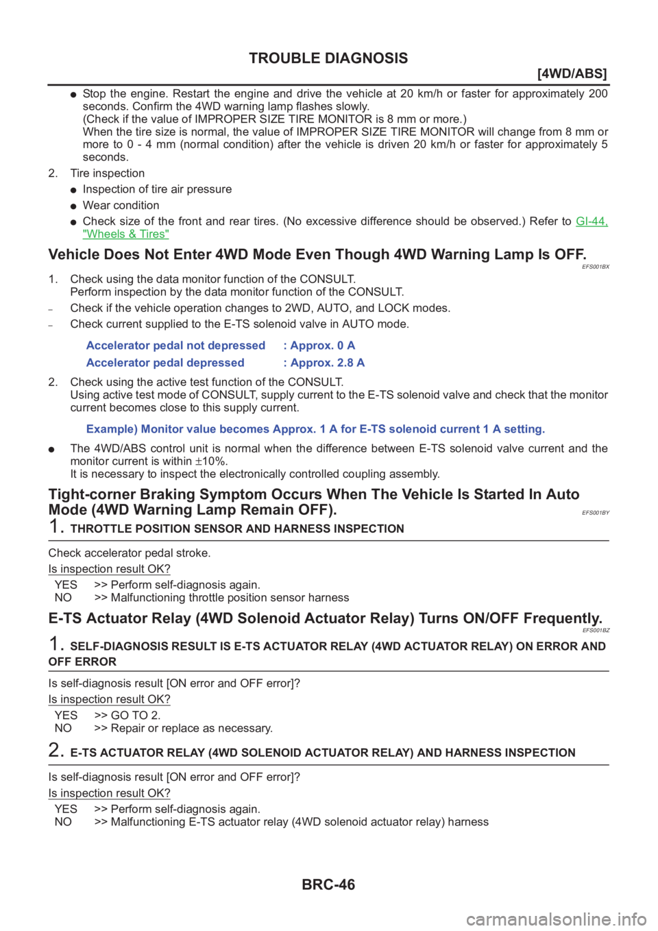
BRC-46
[4WD/ABS]
TROUBLE DIAGNOSIS
●Stop the engine. Restart the engine and drive the vehicle at 20 km/h or faster for approximately 200
seconds. Confirm the 4WD warning lamp flashes slowly.
(Check if the value of IMPROPER SIZE TIRE MONITOR is 8 mm or more.)
When the tire size is normal, the value of IMPROPER SIZE TIRE MONITOR will change from 8 mm or
more to 0 - 4 mm (normal condition) after the vehicle is driven 20 km/h or faster for approximately 5
seconds.
2. Tire inspection
●Inspection of tire air pressure
●Wear condition
●Check size of the front and rear tires. (No excessive difference should be observed.) Refer to GI-44,
"Wheels & Tires"
Vehicle Does Not Enter 4WD Mode Even Though 4WD Warning Lamp Is OFF.EFS001BX
1. Check using the data monitor function of the CONSULT.
Perform inspection by the data monitor function of the CONSULT.
–Check if the vehicle operation changes to 2WD, AUTO, and LOCK modes.
–Check current supplied to the E-TS solenoid valve in AUTO mode.
2. Check using the active test function of the CONSULT.
Using active test mode of CONSULT, supply current to the E-TS solenoid valve and check that the monitor
current becomes close to this supply current.
●The 4WD/ABS control unit is normal when the difference between E-TS solenoid valve current and the
monitor current is within ±10%.
It is necessary to inspect the electronically controlled coupling assembly.
Tight-corner Braking Symptom Occurs When The Vehicle Is Started In Auto
Mode (4WD Warning Lamp Remain OFF).
EFS001BY
1. THROTTLE POSITION SENSOR AND HARNESS INSPECTION
Check accelerator pedal stroke.
Is inspection result OK?
YES >> Perform self-diagnosis again.
NO >> Malfunctioning throttle position sensor harness
E-TS Actuator Relay (4WD Solenoid Actuator Relay) Turns ON/OFF Frequently.EFS001BZ
1. SELF-DIAGNOSIS RESULT IS E-TS ACTUATOR RELAY (4WD ACTUATOR RELAY) ON ERROR AND
OFF ERROR
Is self-diagnosis result [ON error and OFF error]?
Is inspection result OK?
YES >> GO TO 2.
NO >> Repair or replace as necessary.
2. E-TS ACTUATOR RELAY (4WD SOLENOID ACTUATOR RELAY) AND HARNESS INSPECTION
Is self-diagnosis result [ON error and OFF error]?
Is inspection result OK?
YES >> Perform self-diagnosis again.
NO >> Malfunctioning E-TS actuator relay (4WD solenoid actuator relay) harness Accelerator pedal not depressed : Approx. 0 A
Accelerator pedal depressed : Approx. 2.8 A
Example) Monitor value becomes Approx. 1 A for E-TS solenoid current 1 A setting.
Page 2843 of 3833
GENERAL INFORMATION
BRC-59
[ESP/TCS/ABS]
C
D
E
G
H
I
J
K
L
MA
B
BRC
GENERAL INFORMATIONPFP:00000
Fail-SafeEFS0019S
ABS SYSTEM
If a malfunction occurs in the electrical system, the ABS warning lamp, ESP OFF indicator lamp, and SLIP
indicator lamp in the meter will turn ON. In this condition, the ESP/TCS/ABS and EBD become one of the fol-
lowing conditions by the fail-safe function.
1. Only EBD operates. The same condition as that of models without ESP/TCS/ABS
2. ESP/TCS/ABS and EBD do not operate. Only normal brake operates on 4 wheels.
NOTE:
In the step 1 shown above, the self-diagnosis is carried out at the ignition switch is turned ON and when the
vehicle initial starts. ABS self-diagnosis noise may be heard as usual.
ESP/TCS SYSTEM
If a malfunction occurs in the electrical system, the ESP OFF indicator lamp and SLIP indicator lamp in the
meter turn on. In this condition, ESP/TCS will be deactivated and it becomes equal to that of models without
ESP/TCS. However, ABS is controlled normally.
If a malfunction occurs in the throttle control system, ESP/TCS control does not operate. Only ABS control
operates normally.
CAUTION:
If the fail-safe function operates, carry out the self-diagnosis for ESP/TCS/ABS control system.
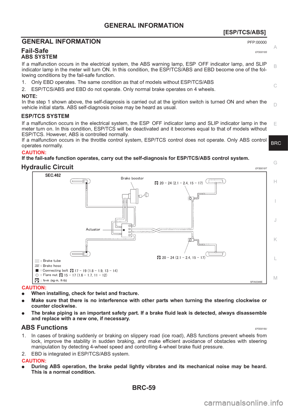
Hydraulic Circuit EFS0019T
CAUTION:
●When installing, check for twist and fracture.
●Make sure that there is no interference with other parts when turning the steering clockwise or
counter clockwise.
●The brake piping is an important safety part. If a brake fluid leak is detected, always disassemble
and replace with a new one, if necessary.
ABS FunctionsEFS0019U
1. In cases of braking suddenly or braking on slippery road (ice road), ABS functions prevent wheels from
lock, improve the stability in sudden braking, and make efficient avoidance of obstacles with steering
manipulation by detecting 4-wheel speed and controlling 4-wheel brake fluid pressure.
2. EBD is integrated in ESP/TCS/ABS system.
CAUTION:
●During ABS operation, the brake pedal lightly vibrates and its mechanical noise may be heard.
This is a normal condition.
SFIA0346E
Page 2860 of 3833
BRC-76
[ESP/TCS/ABS]
TROUBLE DIAGNOSIS
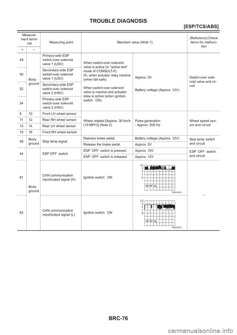
49
Body
groundPrimary-side ESP
switch-over solenoid
valve 1 (USV)When switch-over solenoid
valve is active (in “active test”
mode of CONSULT-II)
Or, when actuator relay inactive
(when fail-safe)
When switch-over solenoid
valve is inactive and actuator
relay is active (when ignition
switch ON)Approx. 0V
Battery voltage (Approx. 12V)Switch-over sole-
noid valve and cir-
cuit 50Secondary-side ESP
switch-over solenoid
valve 1 (USV)
52Secondary-side ESP
switch-over solenoid
valve 2 (HSV)
54Primary-side ESP
switch-over solenoid
valve 2 (HSV)
8 10 Front LH wheel sensor
Wheel rotated [Approx. 30 km/h
(19 MPH)] (Note 2)Pulse generation
: Approx. 200 HzWheel speed sen-
sor and circuit 11 12 Rear RH wheel sensor
13 14 Rear LH wheel sensor
15 16 Front RH wheel sensor
48Body
groundStop lamp signalDepress brake pedal. Battery voltage (Approx. 12V)
Stop lamp switch
and circuit
Release the brake pedal. Approx. 0V
44
Body
groundESP OFF switchESP OFF switch is pressed. Approx. 10V
ESP OFF switch
and circuit
ESP OFF switch is released. Approx. 12V
61CAN communication
input/output signal (H)Ignition switch ON
–
63CAN communication
input/output signal (L)Ignition switch ON Measure-
ment termi-
nalMeasuring point Standard value (Note 1)(Reference) Check
items for malfunc-
tion
+–
PBIA0224J
PBIA0223J
Page 2870 of 3833
BRC-86
[ESP/TCS/ABS]
TROUBLE DIAGNOSIS
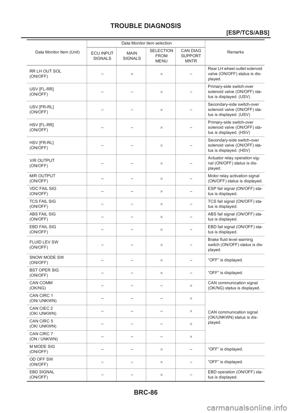
RR LH OUT SOL
(ON/OFF)–××–Rear LH wheel outlet solenoid
valve (ON/OFF) status is dis-
played.
USV [FL-RR]
(ON/OFF)––×–Primary-side switch-over
solenoid valve (ON/OFF) sta-
tus is displayed. (USV)
USV [FR-RL]
(ON/OFF)––×–Secondary-side switch-over
solenoid valve (ON/OFF) sta-
tus is displayed. (USV)
HSV [FL-RR]
(ON/OFF)––×–Primary-side switch-over
solenoid valve (ON/OFF) sta-
tus is displayed. (HSV)
HSV [FR-RL]
(ON/OFF)––×–Secondary-side switch-over
solenoid valve (ON/OFF) sta-
tus is displayed. (HSV)
V/R OUTPUT
(ON/OFF)––×–Actuator relay operation sig-
nal (ON/OFF) status is dis-
played.
M/R OUTPUT
(ON/OFF)––×–Motor relay activation signal
(ON/OFF) status is displayed.
VDC FAIL SIG
(ON/OFF)––×–ESP fail signal (ON/OFF) sta-
tus is displayed.
TCS FAIL SIG
(ON/OFF)––×–TCS fail signal (ON/OFF) sta-
tus is displayed.
ABS FAIL SIG
(ON/OFF)––×–ABS fail signal (ON/OFF) sta-
tus is displayed.
EBD FAIL SIG
(ON/OFF)––×–EBD fail signal (ON/OFF) sta-
tus is displayed.
FLUID LEV SW
(ON/OFF)––×–Brake fluid level warning
switch (ON/OFF) status is dis-
played.
SNOW MODE SW
(ON/OFF)––×– “OFF” is displayed.
BST OPER SIG
(ON/OFF)––×– “OFF” is displayed.
CAN COMM
(OK/NG)
–––×CAN communication signal
(OK/NG) status is displayed.
CAN CIRC 1
(ON/ UNKWN)–––×
CAN communication signal
(OK/UNKWN) status is dis-
played. CAN CIEC 2
(OK/ UNKWN)–––×
CAN CIRC 5
(OK/ UNKWN)–––×
CAN CIRC 7
(ON / UNKWN)–––×
M MODE SIG
(ON/OFF)––×– “OFF” is displayed.
OD OFF SW
(ON/OFF)––×– “OFF” is displayed.
EBD SIGNAL
(ON/OFF)––×–EBD operation (ON/OFF) sta-
tus is displayed. Data Monitor Item (Unit)Data Monitor item selection
Remarks
ECU INPUT
SIGNALSMAIN
SIGNALSSELECTION
FROM
MENUCAN DIAG
SUPPORT
MNTR
Page 2934 of 3833
PS-24
POWER STEERING OIL PUMP
POWER STEERING OIL PUMP
PFP:49110
On-Vehicle Inspection and ServiceEGS000AF
OIL PUMP PULLEY HYDRAULIC PRESSURE INSPECTION
Before starting following procedure, check tension of belt.
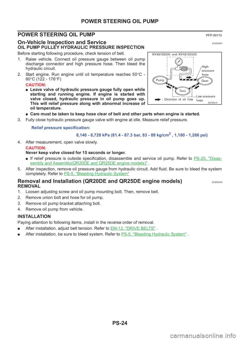
1. Raise vehicle. Connect oil pressure gauge between oil pump
discharge connector and high pressure hose. Then bleed the
hydraulic circuit.
2. Start engine. Run engine until oil temperature reaches 50°C -
80°C (122 - 176°F)
CAUTION:
●Leave valve of hydraulic pressure gauge fully open while
starting and running engine. If engine is started with
valve closed, hydraulic pressure in oil pump goes up.
This will relief pressure along with abnormal increase of
oil temperature.
●Care must be taken to keep hose clear of belt and other parts when engine is started.
3. Fully close hydraulic pressure gauge valve with engine at idle. Measure relief pressure.
4. After measurement, open valve slowly.
CAUTION:
Never keep valve closed for 15 seconds or longer.
●If relief pressure is outside specification, disassemble and service oil pump. Refer to PS-25, "Disas-
sembly and Assembly(QR20DE and QR25DE engine models)" .
5. After inspection, remove oil pressure gauge from hydraulic circuit. Add fluid. Be sure to bleed the system
completely. Refer to PS-5, "
Bleeding Hydraulic System"
Removal and Installation (QR20DE and QR25DE engine models)EGS000AG
REMOVAL
1. Loosen adjusting screw and oil pump mounting bolt. Then, remove belt.
2. Remove union bolt and hose for oil pump.
3. Remove oil pump bracket attaching bolt.
4. Remove oil pump from vehicle.
INSTALLATION
Paying attention to following items, install in the reverse order of removal.
●After installation, adjust belt tension. Refer to EM-12, "DRIVE BELTS" .
●After installation, be sure to bleed system. Refer to PS-5, "Bleeding Hydraulic System" . Relief pressure specification:
8,140 - 8,728 kPa (81.4 - 87.3 bar, 83 - 89 kg/cm
2 , 1,180 - 1,266 psi)
SST834-H
Page 2988 of 3833
SB-6
SEAT BELT WARNING SYSTEM
SEAT BELT WARNING SYSTEM
PFP:25045
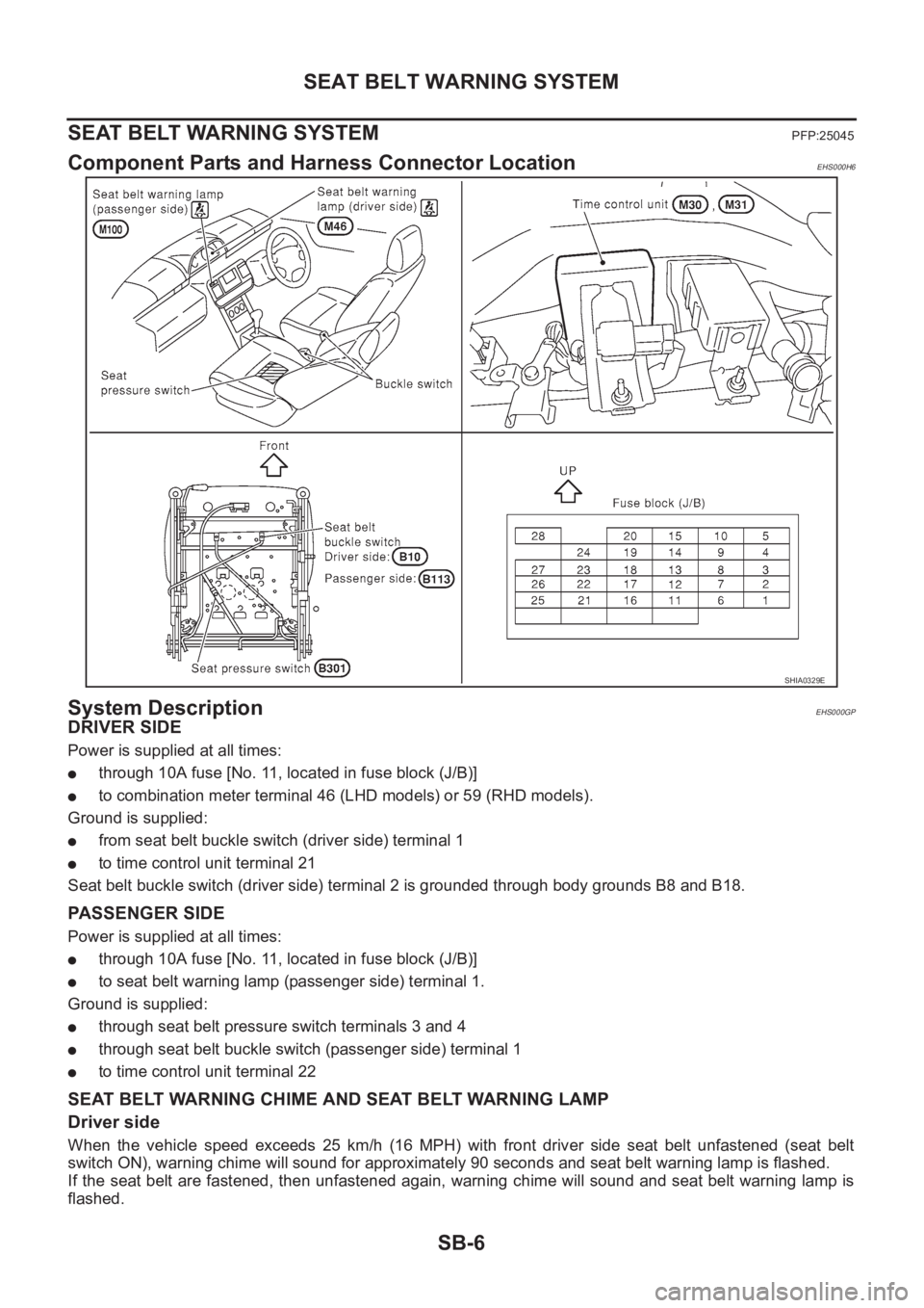
Component Parts and Harness Connector LocationEHS000H6
System DescriptionEHS000GP
DRIVER SIDE
Power is supplied at all times:
●through 10A fuse [No. 11, located in fuse block (J/B)]
●to combination meter terminal 46 (LHD models) or 59 (RHD models).
Ground is supplied:
●from seat belt buckle switch (driver side) terminal 1
●to time control unit terminal 21
Seat belt buckle switch (driver side) terminal 2 is grounded through body grounds B8 and B18.
PASSENGER SIDE
Power is supplied at all times:
●through 10A fuse [No. 11, located in fuse block (J/B)]
●to seat belt warning lamp (passenger side) terminal 1.
Ground is supplied:
●through seat belt pressure switch terminals 3 and 4
●through seat belt buckle switch (passenger side) terminal 1
●to time control unit terminal 22
SEAT BELT WARNING CHIME AND SEAT BELT WARNING LAMP
Driver side
When the vehicle speed exceeds 25 km/h (16 MPH) with front driver side seat belt unfastened (seat belt
switch ON), warning chime will sound for approximately 90 seconds and seat belt warning lamp is flashed.
If the seat belt are fastened, then unfastened again, warning chime will sound and seat belt warning lamp is
flashed.
SHIA0329E