ECO mode NISSAN X-TRAIL 2001 Service Repair Manual
[x] Cancel search | Manufacturer: NISSAN, Model Year: 2001, Model line: X-TRAIL, Model: NISSAN X-TRAIL 2001Pages: 3833, PDF Size: 39.49 MB
Page 3582 of 3833
DI-24
COMBINATION METERS (RHD MODELS)
COMBINATION METERS (RHD MODELS)
PFP:24810
System DescriptionEKS0030H
UNIFIED CONTROL METER
●Speedometer, odo/trip meter, tachometer, fuel gauge and water temperature gauge are controlled totally
by control unit built-in combination meter.
●Digital meter is adopted for odo/trip meter.*
*The record of the odo meter is kept even if the battery cable is disconnected. The record of the trip meter
is erased when the battery cable is disconnected.
●Odo/trip meter segment can be checked in diagnosis mode.
●Meter/gauge can be checked in diagnosis mode.
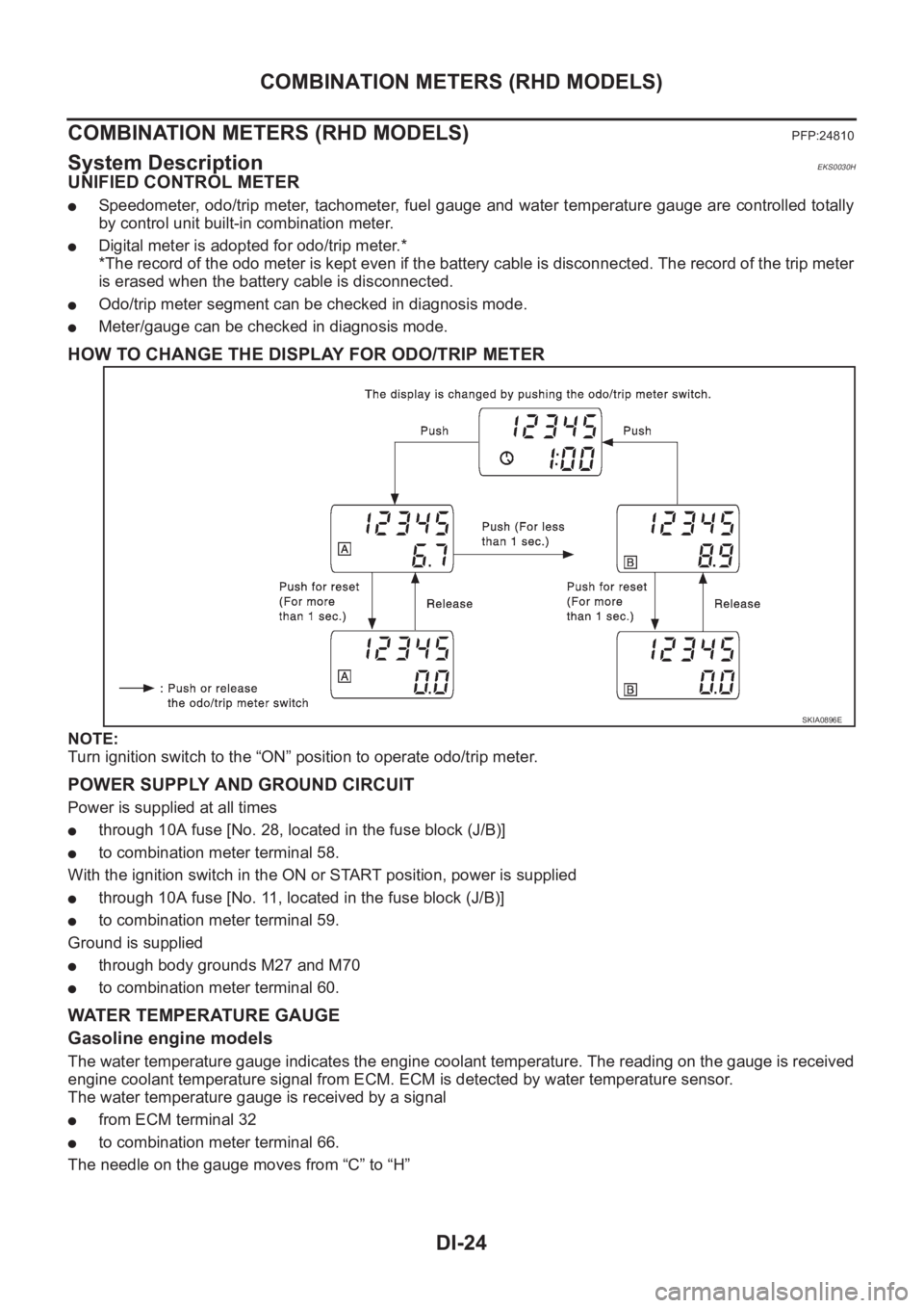
HOW TO CHANGE THE DISPLAY FOR ODO/TRIP METER
NOTE:
Turn ignition switch to the “ON” position to operate odo/trip meter.
POWER SUPPLY AND GROUND CIRCUIT
Power is supplied at all times
●through 10A fuse [No. 28, located in the fuse block (J/B)]
●to combination meter terminal 58.
With the ignition switch in the ON or START position, power is supplied
●through 10A fuse [No. 11, located in the fuse block (J/B)]
●to combination meter terminal 59.
Ground is supplied
●through body grounds M27 and M70
●to combination meter terminal 60.
WATER TEMPERATURE GAUGE
Gasoline engine models
The water temperature gauge indicates the engine coolant temperature. The reading on the gauge is received
engine coolant temperature signal from ECM. ECM is detected by water temperature sensor.
The water temperature gauge is received by a signal
●from ECM terminal 32
●to combination meter terminal 66.
The needle on the gauge moves from “C” to “H”
SKIA0896E
Page 3588 of 3833
DI-30
COMBINATION METERS (RHD MODELS)
Meter/Gauge Operation and Odo/Trip Meter Segment Check in Diagnosis Mode
EKS0030M
DIAGNOSIS FUNCTION
●Odo/trip meter segment can be checked in diagnosis mode.
●Meters/gauges can be checked in diagnosis mode.
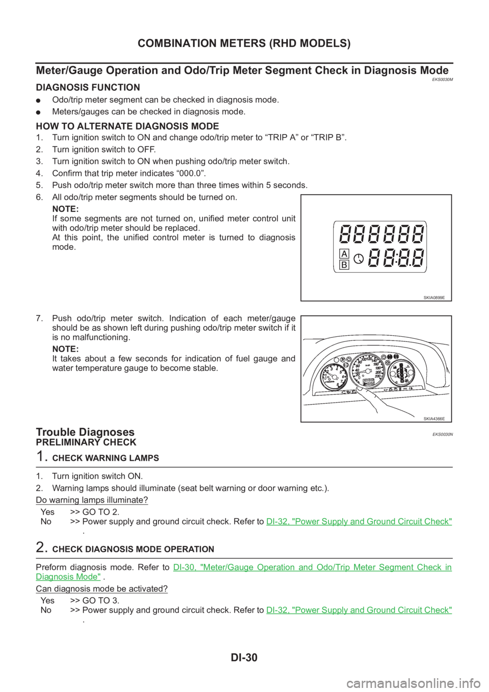
HOW TO ALTERNATE DIAGNOSIS MODE
1. Turn ignition switch to ON and change odo/trip meter to “TRIP A” or “TRIP B”.
2. Turn ignition switch to OFF.
3. Turn ignition switch to ON when pushing odo/trip meter switch.
4. Confirm that trip meter indicates “000.0”.
5. Push odo/trip meter switch more than three times within 5 seconds.
6. All odo/trip meter segments should be turned on.
NOTE:
If some segments are not turned on, unified meter control unit
with odo/trip meter should be replaced.
At this point, the unified control meter is turned to diagnosis
mode.
7. Push odo/trip meter switch. Indication of each meter/gauge
should be as shown left during pushing odo/trip meter switch if it
is no malfunctioning.
NOTE:
It takes about a few seconds for indication of fuel gauge and
water temperature gauge to become stable.
Trouble DiagnosesEKS0030N
PRELIMINARY CHECK
1. CHECK WARNING LAMPS
1. Turn ignition switch ON.
2. Warning lamps should illuminate (seat belt warning or door warning etc.).
Do warning lamps illuminate?
Yes >> GO TO 2.
No >> Power supply and ground circuit check. Refer to DI-32, "
Power Supply and Ground Circuit Check"
.
2. CHECK DIAGNOSIS MODE OPERATION
Preform diagnosis mode. Refer to DI-30, "
Meter/Gauge Operation and Odo/Trip Meter Segment Check in
Diagnosis Mode" .
Can diagnosis mode be activated?
Yes >> GO TO 3.
No >> Power supply and ground circuit check. Refer to DI-32, "
Power Supply and Ground Circuit Check"
.
SKIA0899E
SKIA4366E
Page 3673 of 3833
CAN SYSTEM (FOR A/T MODELS)
LAN-11
[CAN]
C
D
E
F
G
H
I
J
L
MA
B
LAN
5.ECM/TCM INTERNAL CIRCUIT INSPECTION
Check components inspection. Refer to LAN-11, "
ECM/TCM INTERNAL CIRCUIT INSPECTION"
OK or NG
OK >> Reconnect all connectors to perform “SELF-DIAG RESULTS” and “DATA MONITOR” for
“ENGINE” and “A/T”. Refer to the following:
●EC-854, "DTC U1000 CAN COMMUNICATION LINE" (QR20 WITH EURO-OBD) for “ENGINE”
●EC-1199, "DTC U1000 CAN COMMUNICATION LINE" (QR20 WITHOUT EURO-OBD) for
“ENGINE”
●EC-122, "DTC U1000 CAN COMMUNICATION LINE" (QR25 WITH EURO-OBD) for “ENGINE”
●EC-513, "DTC U1000 CAN COMMUNICATION LINE" (QR25 WITHOUT EURO-OBD) for
“ENGINE”
●AT-190, "DTC U1000 CAN COMMUNICATION LINE" (EURO-OBD) for “A/T”
●AT-403, "CAN COMMUNICATION LINE" (ALL) for “A/T”
NG >> Replace ECM and/or TCM.
Component InspectionEKS002AI
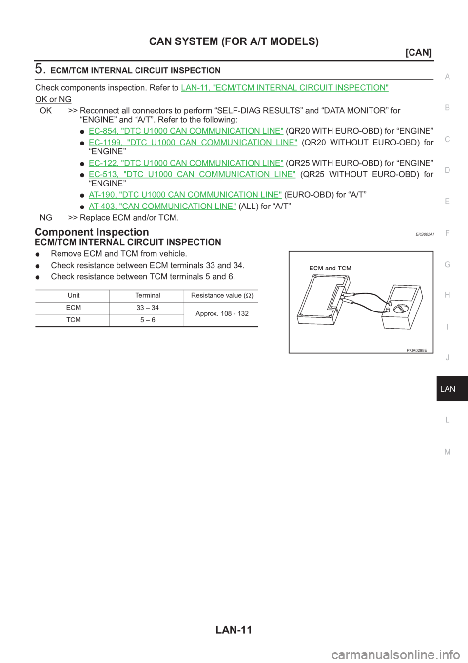
ECM/TCM INTERNAL CIRCUIT INSPECTION
●Remove ECM and TCM from vehicle.
●Check resistance between ECM terminals 33 and 34.
●Check resistance between TCM terminals 5 and 6.
Unit Terminal Resistance value (Ω)
ECM 33 – 34
Approx. 108 - 132
TCM 5 – 6
PKIA0298E
Page 3680 of 3833
LAN-18
[CAN]
CAN SYSTEM (FOR M/T MODELS)
2. CHECK HARNESS FOR OPEN CIRCUIT
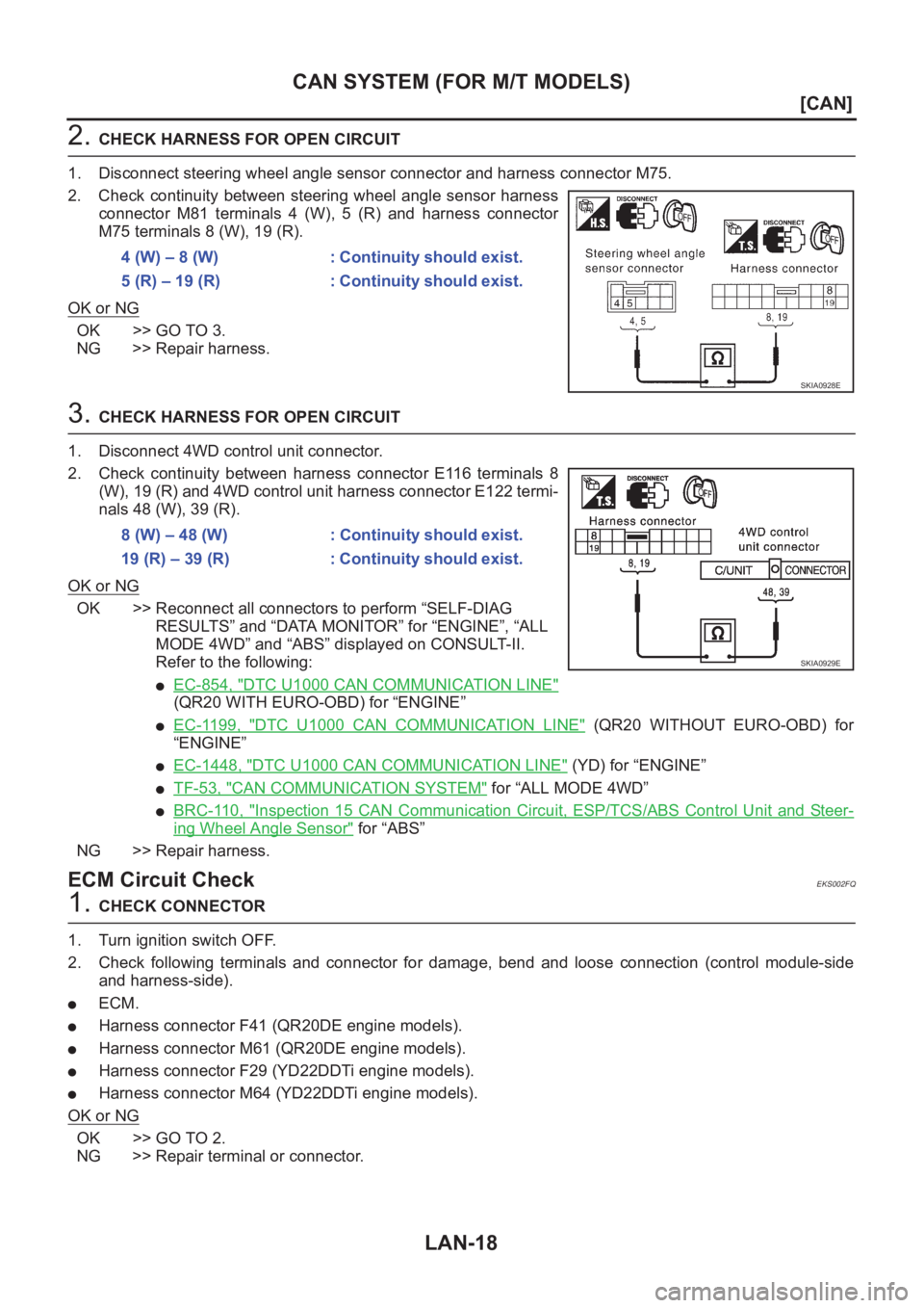
1. Disconnect steering wheel angle sensor connector and harness connector M75.
2. Check continuity between steering wheel angle sensor harness
connector M81 terminals 4 (W), 5 (R) and harness connector
M75 terminals 8 (W), 19 (R).
OK or NG
OK >> GO TO 3.
NG >> Repair harness.
3. CHECK HARNESS FOR OPEN CIRCUIT
1. Disconnect 4WD control unit connector.
2. Check continuity between harness connector E116 terminals 8
(W), 19 (R) and 4WD control unit harness connector E122 termi-
nals 48 (W), 39 (R).
OK or NG
OK >> Reconnect all connectors to perform “SELF-DIAG
RESULTS” and “DATA MONITOR” for “ENGINE”, “ALL
MODE 4WD” and “ABS” displayed on CONSULT-II.
Refer to the following:
●EC-854, "DTC U1000 CAN COMMUNICATION LINE"
(QR20 WITH EURO-OBD) for “ENGINE”
●EC-1199, "DTC U1000 CAN COMMUNICATION LINE" (QR20 WITHOUT EURO-OBD) for
“ENGINE”
●EC-1448, "DTC U1000 CAN COMMUNICATION LINE" (YD) for “ENGINE”
●TF-53, "CAN COMMUNICATION SYSTEM" for “ALL MODE 4WD”
●BRC-110, "Inspection 15 CAN Communication Circuit, ESP/TCS/ABS Control Unit and Steer-
ing Wheel Angle Sensor" for “ABS”
NG >> Repair harness.
ECM Circuit CheckEKS002FQ
1. CHECK CONNECTOR
1. Turn ignition switch OFF.
2. Check following terminals and connector for damage, bend and loose connection (control module-side
and harness-side).
●ECM.
●Harness connector F41 (QR20DE engine models).
●Harness connector M61 (QR20DE engine models).
●Harness connector F29 (YD22DDTi engine models).
●Harness connector M64 (YD22DDTi engine models).
OK or NG
OK >> GO TO 2.
NG >> Repair terminal or connector.4 (W) – 8 (W) : Continuity should exist.
5 (R) – 19 (R) : Continuity should exist.
SKIA0928E
8 (W) – 48 (W) : Continuity should exist.
19 (R) – 39 (R) : Continuity should exist.
SKIA0929E
Page 3686 of 3833
LAN-24
[CAN]
CAN SYSTEM (FOR M/T MODELS)
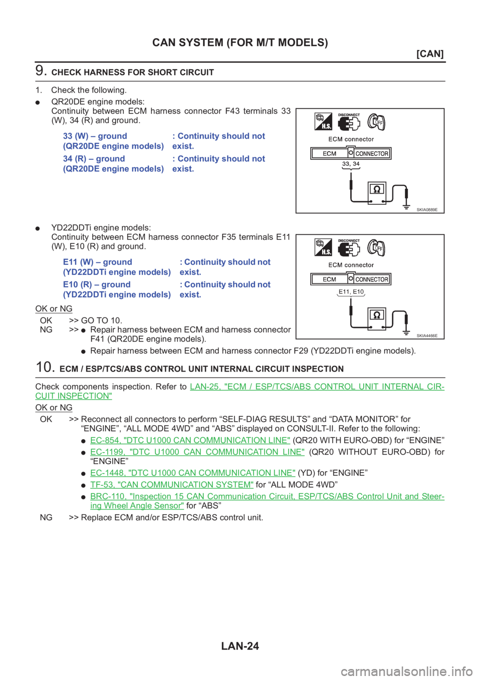
9. CHECK HARNESS FOR SHORT CIRCUIT
1. Check the following.
●QR20DE engine models:
Continuity between ECM harness connector F43 terminals 33
(W), 34 (R) and ground.
●YD22DDTi engine models:
Continuity between ECM harness connector F35 terminals E11
(W), E10 (R) and ground.
OK or NG
OK >> GO TO 10.
NG >>
●Repair harness between ECM and harness connector
F41 (QR20DE engine models).
●Repair harness between ECM and harness connector F29 (YD22DDTi engine models).
10. ECM / ESP/TCS/ABS CONTROL UNIT INTERNAL CIRCUIT INSPECTION
Check components inspection. Refer to LAN-25, "
ECM / ESP/TCS/ABS CONTROL UNIT INTERNAL CIR-
CUIT INSPECTION"
OK or NG
OK >> Reconnect all connectors to perform “SELF-DIAG RESULTS” and “DATA MONITOR” for
“ENGINE”, “ALL MODE 4WD” and “ABS” displayed on CONSULT-II. Refer to the following:
●EC-854, "DTC U1000 CAN COMMUNICATION LINE" (QR20 WITH EURO-OBD) for “ENGINE”
●EC-1199, "DTC U1000 CAN COMMUNICATION LINE" (QR20 WITHOUT EURO-OBD) for
“ENGINE”
●EC-1448, "DTC U1000 CAN COMMUNICATION LINE" (YD) for “ENGINE”
●TF-53, "CAN COMMUNICATION SYSTEM" for “ALL MODE 4WD”
●BRC-110, "Inspection 15 CAN Communication Circuit, ESP/TCS/ABS Control Unit and Steer-
ing Wheel Angle Sensor" for “ABS”
NG >> Replace ECM and/or ESP/TCS/ABS control unit.33 (W) – ground
(QR20DE engine models): Continuity should not
exist.
34 (R) – ground
(QR20DE engine models): Continuity should not
exist.
SKIA0889E
E11 (W) – ground
(YD22DDTi engine models): Continuity should not
exist.
E10 (R) – ground
(YD22DDTi engine models): Continuity should not
exist.
SKIA4466E
Page 3691 of 3833
AUDIO
AV-3
C
D
E
F
G
H
I
J
L
MA
B
AV
AUDIOPFP:28111
System DescriptionEKS002F2
Refer to Owner's Manual for audio system operating instructions.
Power is supplied at all times
●to audio unit terminal 3 and
●to CD auto changer terminal 32
●through 15A fuse (No. 32, located in the fuse and fusible link box).
With the ignition switch in the ACC or ON position, power is supplied
●to audio unit terminal 6 and
●to CD auto changer terminal 36
●through 10A fuse [No. 4, located in the fuse block (J/B)]
Ground is supplied through the case of the audio unit.
Audio signals are supplied
●through audio unit terminals 5, 7, 9, 10, 11, 13, 15, 16
●to terminals 1 and 2 of front door speaker LH and RH,
●to terminals 1 and 2 of rear door speaker LH and RH and
●to terminals 1 and 2 of tweeter LH and RH (with 6-speakers)
NATS AUDIO LINK
Description
The link with the NATS IMMU implies that the audio unit can basically only be operated if connected to the
matching NATS IMMU to which the audio unit was initially fitted on the production line.
Since radio operation is impossible after the link with the NATS is disrupted theft of the audio unit is basically
useless since special equipment is required to reset the audio unit.
Initialization process for audio units that are linked to the NAT S I M M U
New audio units will be delivered to the factories in the “NEW” state, i.e. ready to be linked with the vehicle's
NATS. When the audio unit in “NEW” state is first switched on at the factory, it will start up communication with
the vehicle's immobilizer control unit (IMMU) and send a code (the “audio unit Code”) to the IMMU. The IMMU
will then store this code, which is unique to each audio unit, in its (permanent) memory.
Upon receipt of the code by the IMMU, the NATS will confirm correct receipt of the audio unit code to the audio
unit. Hereafter, the audio unit will operate as normal.
During the initialization process, “NEW” is displayed on the audio unit display. Normally though, communica-
tion between audio unit and IMMU takes such a short time (300 ms) that the audio unit seems to switch on
directly without showing “NEW” on its display.
Normal operation
Each time the audio unit is switched on afterwards, the audio unit code will be verified between the audio unit
and the NATS before the audio unit becomes operational. During the code verification process, “WAIT” is
shown on the audio unit display. Again, the communication takes such a short time (300 ms) that the audio
unit seems to switch on directly without showing “WAIT” on its display.
When the radio is locked
In case of a audio unit being linked with the vehicle's NATS (immobilizer system), disconnection of the link
between the audio unit and the IMMU will cause the audio unit to switch into the lock (“SECURE”) mode in
which the audio unit is fully inoperative. Hence, repair of the audio unit is basically impossible, unless the
audio unit is reset to the “NEW” state for which special decoding equipment is required.
Clarion has provided their authorized service representatives with so called “decoder boxes” which can bring
the audio unit back to the “NEW” state, enabling the audio unit to be switched on after which repair can be car-
ried out. Subsequently, when the repaired audio unit is delivered to the final user again, it will be in the “NEW”
state to enable re-linking the audio unit to the vehicle's immobilizer system. As a result of the above, repair of
the audio unit can only be done by an authorized Clarion representative (when the owner of the vehicle
requests repair and can show personal identification).
Page 3700 of 3833
AV-12
AUDIO
Trouble Diagnoses
EKS002F5
AUDIO UNIT
Symptom Possible causes Repair order
Audio unit inoperative (no digital display
and no sound from speakers).1. 10A fuse
2. Poor audio unit case ground
3. Audio unit1. Check 10A fuse [No. 4, located
in fuse block (J/B)]. Turn ignition
switch ON and verify that battery
positive voltage is present at ter-
minal 6 of audio unit.
2. Check audio unit case ground.
3. Remove audio unit for repair.
Audio unit presets are lost when ignition
switch is turned OFF.1. 15A fuse
2. Audio unit1. Check 15A fuse (No. 32, located
in fuse and fusible link box) and
verify that battery positive volt-
age is present at terminal 3 of
audio unit.
2. Remove audio unit for repair.
Individual rear speaker is noisy or inopera-
tive.1. Each speaker
2. Output circuit to each speaker1. Check speaker.
2. Check the output circuits to each
speaker between audio unit and
each speaker.
AM/FM stations are weak or noisy. 1. Roof antenna
2. Audio unit ground
3. Audio unit1. Check roof antenna.
2. Check audio unit ground condi-
tion.
3. Remove audio unit for repair.
Audio unit generates noise in AM and FM
modes with engine running.1. Poor audio unit ground
2. Loose or missing ground bonding straps
3. Ignition condenser or rear window defogger
noise suppressor condenser
4. Ignition coil or secondary wiring
5. Audio unit1. Check audio unit ground.
2. Check ground bonding straps.
3. Replace ignition condenser or
rear window defogger noise sup-
pressor condenser.
4. Check ignition coil and second-
ary wiring.
5. Remove audio unit for repair.
Audio unit generates noise in AM and FM
modes with accessories on (switch pops
and motor noise).1. Poor audio unit ground
2. Antenna
3. Accessory ground
4. Malfunctioning accessory1. Check audio unit ground.
2. Check antenna.
3. Check accessory ground.
4. Replace accessory.
Page 3784 of 3833
MA-4
DESCRIPTION
DESCRIPTION
PFP:00000
Pre-delivery Inspection ItemsELS000AK
Shown below are Pre-delivery Inspection Items required for the new vehicle. It is recommended that
necessary items other than those listed here be added, paying due regard to the conditions in each
country.
Perform applicable items on each model. Consult text of this section for specifications.
UNDER HOOD — engine off
Radiator coolant level and coolant hose connections for leaks
Battery fluid level, specific gravity and conditions of battery terminals
Drive belts tension
Fuel filter for water or dusts (Diesel only), and fuel lines and connections for leaks
Engine oil level and oil leaks
Clutch and brake reservoir fluid level and fluid lines for leaks
Windshield and rear window washer and headlamp cleaner reservoir fluid level
Power steering reservoir fluid level and hose connections for leaks
ON INSIDE AND OUTSIDE
Remove front spring/strut spacer (If applicable)
Operation of all instruments, gauges, lights and accessories
Operation of horn(s), wiper and washer
Steering lock for operation
Check air conditioner for gas leaks
Front and rear seats, and seat belts for operation
All moldings, trims and fittings for fit and alignment
All windows for operation and alignment
Hood, trunk lid, door panels for fit and alignment
Latches, keys and locks for operation
Weatherstrips for adhesion and fit
Headlamp aiming
Tighten wheel nuts (Inc. inner nuts if applicable)
Tire pressure (Inc. spare tire)
Check front wheels for toe-in
Install clock/voltmeter/room lamp fuse (If applicable)
Install deodorizing filter to air conditioner (If applicable)
Remove wiper blade protectors (If applicable)
UNDER BODY
Manual transmission/transaxle, transfer and differential gear oil level
Brake and fuel lines and oil/fluid reservoirs for leaks
Tighten bolts and nuts of steering linkage and gear box, suspension, propeller shafts and drive shafts
Tighten rear body bolts and nuts (Models with wooden bed only)
ROAD TEST
Clutch operation
Parking brake operation
Service brake operation
Automatic transmission/transaxle shift timing and kickdown
Steering control and returnability
Engine performance
Page 3787 of 3833
PERIODIC MAINTENANCE
MA-7
C
D
E
F
G
H
I
J
K
MA
B
MA
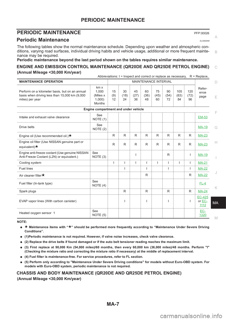
PERIODIC MAINTENANCEPFP:00026
Periodic MaintenanceELS000AM
The following tables show the normal maintenance schedule. Depending upon weather and atmospheric con-
ditions, varying road surfaces, individual driving habits and vehicle usage, additional or more frequent mainte-
nance may be required.
Periodic maintenance beyond the last period shown on the tables requires similar maintenance.
ENGINE AND EMISSION CONTROL MAINTENANCE (QR20DE AND QR25DE PETROL ENGINE)
(Annual Mileage <30,000 Km/year)
Abbreviations: I = Inspect and correct or replace as necessary,R = Replace,.
NOTE:
● Maintenance items with “ ” should be performed more frequently according to “Maintenance Under Severe Driving
Conditions”.
●(1)Periodic maintenance is not required. However, if valve noise increases, check valve clearance.
●(2) Replace the drive belts if found damaged or if the auto belt tensioner reading reaches the maximum limit.
●(3) First replace at 90,000 Km (54,000 miles)/60 months, then every 60,000 km (36,000 miles)/48 months. Perform "I"
(Checking the mixture ratio and correcting the mixture ratio if necessary) at the middle of replacement interval.
●(4) Fuel filter is maintenance-free. For service procedures, refer to FL section.
●(5) Perform only according to "Maintenance Under Severe Driving conditions" for models without Euro-OBD system. For
models with Euro-OBD system, periodic maintenance is not required.
CHASSIS AND BODY MAINTENANCE (QR20DE AND QR25DE PETROL ENGINE)
(Annual Mileage <30,000 Km/year)
MAINTENANCE OPERATIONMAINTENANCE INTERVAL
Refer-
ence
page Perform on a kilometer basis, but on an annual
basis when driving less than 15,000 km (9,000
miles) per yearkm x
1,000
(Miles x
1,000)
Months15
(9)
1230
(18)
2445
(27)
3660
(36)
4875
(45)
6090
(54)
72105
(63)
84120
(72)
96
Engine compartment and under vehicle
Intake and exhaust valve clearanceSee
NOTE (1)EM-53
Drive beltsSee
NOTE (2)MA-19
Engine oil (Use recommended oil.)R RRRRRRRMA-23
Engine oil filter (Use NISSAN genuine part or
equivalent)R RRRRRRRMA-23
Engine anti-freeze coolant (Use genuine NISSAN
Anti-Freeze Coolant (L2N) or equivalent.)See
NOTE (3)IRIMA-19
Cooling system II IIIIIIMA-21
Fuel lines I I I IMA-22
Air cleaner filterRRMA-22
Fuel filter (In-tank type)See
NOTE (4)FL-4
Spark plugs R R R RMA-24
EVAP vapor lines (With carbon canister) I I I IEC-425or EC-
111 2
Heated oxygen sensor 1 See
NOTE (5)EC-1320
Page 3791 of 3833
PERIODIC MAINTENANCE
MA-11
C
D
E
F
G
H
I
J
K
MA
B
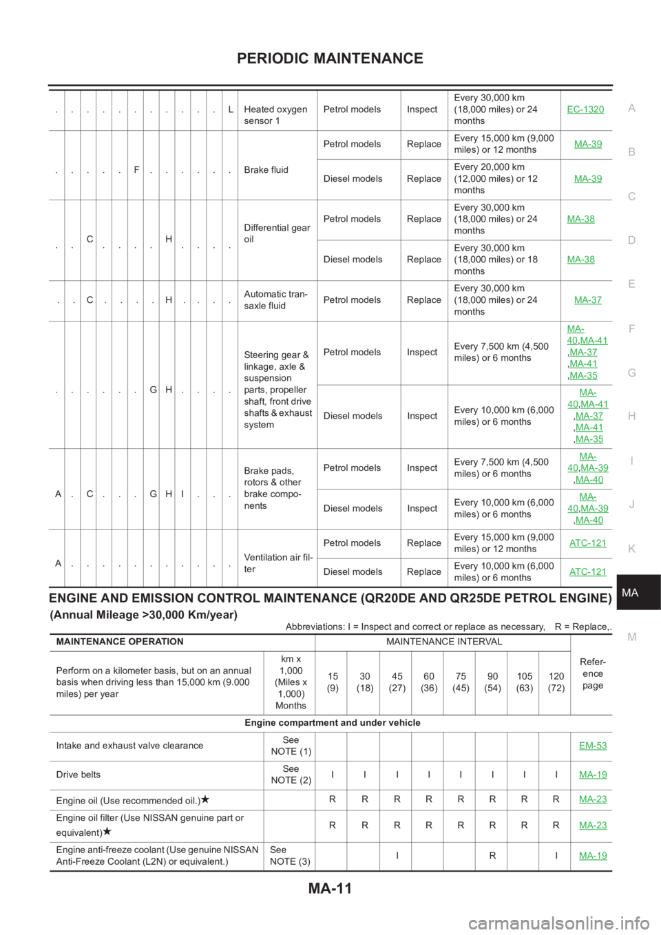
MAENGINE AND EMISSION CONTROL MAINTENANCE (QR20DE AND QR25DE PETROL ENGINE)
(Annual Mileage >30,000 Km/year)
Abbreviations: I = Inspect and correct or replace as necessary,R = Replace,. ...........LHeated oxygen
sensor 1Petrol models InspectEvery 30,000 km
(18,000 miles) or 24
monthsEC-1320
.....F......Brake fluidPetrol models ReplaceEvery 15,000 km (9,000
miles) or 12 monthsMA-39Diesel models ReplaceEvery 20,000 km
(12,000 miles) or 12
monthsMA-39
..C
....H
....Differential gear
oilPetrol models ReplaceEvery 30,000 km
(18,000 miles) or 24
monthsMA-38
Diesel models ReplaceEvery 30,000 km
(18,000 miles) or 18
monthsMA-38
..C....H....Automatic tran-
saxle fluidPetrol models ReplaceEvery 30,000 km
(18,000 miles) or 24
monthsMA-37
......GH....Steering gear &
linkage, axle &
suspension
parts, propeller
shaft, front drive
shafts & exhaust
systemPetrol models InspectEvery 7,500 km (4,500
miles) or 6 monthsMA-
40,MA-41
,MA-37
,MA-41
,MA-35
Diesel models InspectEvery 10,000 km (6,000
miles) or 6 monthsMA-
40,MA-41
,MA-37
,MA-41
,MA-35
A.C...GHI...Brake pads,
rotors & other
brake compo-
nentsPetrol models InspectEvery 7,500 km (4,500
miles) or 6 monthsMA-
40,MA-39
,MA-40
Diesel models InspectEvery 10,000 km (6,000
miles) or 6 monthsMA-40,MA-39
,MA-40
A...........Ventilation air fil-
terPetrol models ReplaceEvery 15,000 km (9,000
miles) or 12 monthsAT C - 1 2 1Diesel models ReplaceEvery 10,000 km (6,000
miles) or 6 monthsAT C - 1 2 1
MAINTENANCE OPERATIONMAINTENANCE INTERVAL
Refer-
ence
page Perform on a kilometer basis, but on an annual
basis when driving less than 15,000 km (9.000
miles) per yearkm x
1,000
(Miles x
1,000)
Months15
(9)30
(18)45
(27)60
(36)75
(45)90
(54)105
(63)120
(72)
Engine compartment and under vehicle
Intake and exhaust valve clearanceSee
NOTE (1)EM-53
Drive beltsSee
NOTE (2)II IIIIIIMA-19
Engine oil (Use recommended oil.)R RRRRRRRMA-23
Engine oil filter (Use NISSAN genuine part or
equivalent)R RRRRRRRMA-23
Engine anti-freeze coolant (Use genuine NISSAN
Anti-Freeze Coolant (L2N) or equivalent.)See
NOTE (3)IRIMA-19