brake light NISSAN X-TRAIL 2001 Service Service Manual
[x] Cancel search | Manufacturer: NISSAN, Model Year: 2001, Model line: X-TRAIL, Model: NISSAN X-TRAIL 2001Pages: 3833, PDF Size: 39.49 MB
Page 2714 of 3833
FSU-8
COIL SPRING AND SHOCK ABSORBER
COIL SPRING AND SHOCK ABSORBER
PFP:54302
Removal and InstallationEES00074
REMOVAL
1. Remove tires. Remove brake caliper and hung it aside.
CAUTION:
Avoid depressing brake pedal with brake caliper removed.
2. Remove electrical wires of ABS wheel speed sensor from strut.
3. Remove brake hose lock plate.
4. Remove mounting bolts and nuts securing steering knuckle to strut.
5. Remove mounting nuts on upper mounting plate and remove upper mounting plate and strut from vehicle.
INSTALLATION
●Refer to FSU-5, "Components" in “Front Suspension Assembly” for tightening torque. Tighten in the
reverse order of removal.
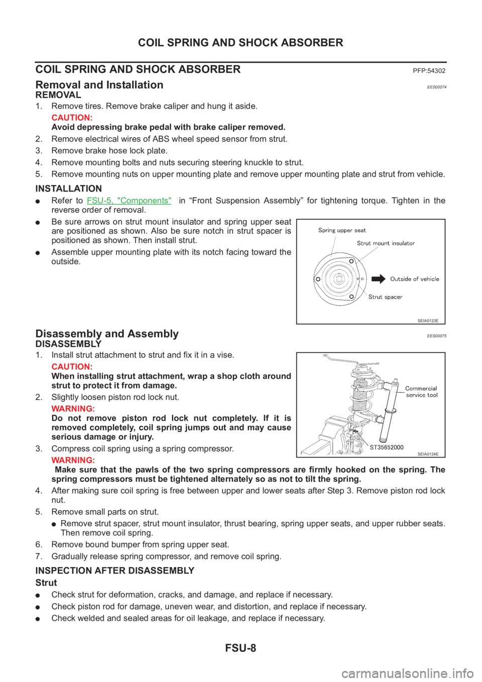
●Be sure arrows on strut mount insulator and spring upper seat
are positioned as shown. Also be sure notch in strut spacer is
positioned as shown. Then install strut.
●Assemble upper mounting plate with its notch facing toward the
outside.
Disassembly and AssemblyEES00075
DISASSEMBLY
1. Install strut attachment to strut and fix it in a vise.
CAUTION:
When installing strut attachment, wrap a shop cloth around
strut to protect it from damage.
2. Slightly loosen piston rod lock nut.
WARNING:
Do not remove piston rod lock nut completely. If it is
removed completely, coil spring jumps out and may cause
serious damage or injury.
3. Compress coil spring using a spring compressor.
WARNING:
Make sure that the pawls of the two spring compressors are firmly hooked on the spring. The
spring compressors must be tightened alternately so as not to tilt the spring.
4. After making sure coil spring is free between upper and lower seats after Step 3. Remove piston rod lock
nut.
5. Remove small parts on strut.
●Remove strut spacer, strut mount insulator, thrust bearing, spring upper seats, and upper rubber seats.
Then remove coil spring.
6. Remove bound bumper from spring upper seat.
7. Gradually release spring compressor, and remove coil spring.
INSPECTION AFTER DISASSEMBLY
Strut
●Check strut for deformation, cracks, and damage, and replace if necessary.
●Check piston rod for damage, uneven wear, and distortion, and replace if necessary.
●Check welded and sealed areas for oil leakage, and replace if necessary.
SEIA0123E
SEIA0124E
Page 2728 of 3833
RSU-8
COIL SPRING AND STRUT
COIL SPRING AND STRUT
PFP:55302
Removal and InstallationEES0007H
REMOVAL
1. Remove tires.
2. Remove brake hose lock plate and remove brake hose from strut.
3. Remove mounting nuts and washers on upper portion of stabilizer connecting rod.
4. Remove strut-to-axle housing mounting bolts and nuts.
5. Remove luggage side lower finisher in luggage compartment. Remove mounting nuts on strut spacer.
Then remove strut from vehicle.
INSTALLATION
●Refer to RSU-5, "Components" for tightening torque. Install in the reverse order of removal.
Disassembly and AssemblyEES0007I
DISASSEMBLY
1. Install strut attachment to strut and fix it in a vise.
CAUTION:
When installing a strut attachment, cover strut with shop
cloth to avoid damage.
2. Remove cap and slightly loosen piston rod lock nut.
CAUTION:
Do not remove piston rod lock nut completely. If it is
removed completely, coil spring jumps out and may cause
serious damage or injury.
3. Compress coil spring using a spring compressor.
CAUTION:
Be sure spring compressor is securely attached to coil spring. Compress coil spring.
4. After making sure coil spring is free between upper and lower seats after Step 3. Remove piston rod lock
nut.
5. Remove small parts on strut.
●Remove strut spacer, strut mount insulator, spring upper seat, upper rubber seat, and bound bumper.
Then remove coil spring from strut.
6. Gradually release spring compressor, and remove coil spring.
INSPECTION AFTER DISASSEMBLY
Strut
●Check strut for deformation, cracks, and damage, and replace if necessary.
●Check piston rod for damage, uneven wear, and distortion, and replace if necessary.
●Check welded and sealed areas for oil leakage, and replace if necessary.
Insulator and Rubber parts.
●Check strut mount insulator for cracks and rubber parts for wear. Replace them if necessary.
Coil Spring
●Check coil spring for cracks, deformation, and damage, and replace if necessary.
SEIA0124E
Page 2790 of 3833

BRC-6
[4WD/ABS]
ALL MODE 4X4 SYSTEM
ALL MODE 4X4 SYSTEM
PFP:47850
System DescriptionEFS001CJ
ABS FUNCTION
●During ABS operation, brake pedal lightly vibrates and its mechanical noise may be heard. This is a nor-
mal condition.
●When starting engine, or just after starting vehicle, brake pedal may vibrate. Also motor operating noise
may be heard from engine compartment. This is a normal status of operation check.
● When vehicle drives on rough, gravel, or snowy (fresh deep snow) road, the following conditions occur.
Stopping distance may be longer than that of vehicles without ABS.
4WD FUNCTION
● Electronically controlled 4WD is controlled by the same control module as that for ABS (4WD/ABS control
unit). 4WD/ABS control unit controls both electronically-controlled 4WD and ABS, based on input signals
from several sensors.
●If electrical system-related malfunction occurred in 4WD/ABS system, control unit illuminates the following
lamps: 4WD warning lamp and/or ABS warning lamp on meter control unit assembly. This notifies driver of
malfunction. At the same time, control unit indicates malfunctioning part detected by self-diagnosis with
flashing pattern of LED. Indication on electronic system diagnosis tester (CONSULT) corresponds to this
flashing pattern as shown below.
Control System DiagramEFS001CK
Self-diagnostic test mode Remarks
Result of self-diagnosis Conformable to 4WD/ABS
Data monitor Conformable to 4WD/ABS
Active testChecks ABS solenoid valve ON/OFF, ABS motor ON/OFF, 4WD sole-
noid
Control unit part No. 4WD/ABS control unit
SFIA0350E
Page 2814 of 3833

BRC-30
[4WD/ABS]
TROUBLE DIAGNOSIS
ABS motor
Touch “ON” and “OFF” on screen. Check ABS motor relay operates
as shown in the following chart.
NOTE:
●If active test is performed with brake pedal depressed, pedal
stroke may be changed. This is a normal condition.
●“TEST STOP” is displayed 10 seconds later from the operation
start.
Active test
4WD solenoid valve
Under the vehicle stopped with engine running, touch UP, DOWN on
screen. Adjust 4WD solenoid command current.
Check the monitor current at that time. If monitor current is within
Approx. ±10%, light switch is normal.
CAUTION:
Do not continuously energize solenoid for long period of time.
Component InspectionEFS001BJ
ABS ACTUATOR
●Disconnect each ABS actuator E69, E70, E71 connector. Con-
firm continuity and resistance value between each pair of ABS
actuator-side terminal.
CAUTION:
Be sure ABS motor is securely grounded.
Operation ON OFF
ABS actuator ON ON
ABS motor ON OFF
SFIA0397E
SDIA0626E
SFIA1099E
Page 2838 of 3833

BRC-54
[ESP/TCS/ABS]
PRECAUTIONS
[ESP/TCS/ABS]PRECAUTIONSPFP:00001
Precautions for Brake SystemEFS0019O
●Recommended fluid is brake fluid “DOT 3” or “DOT 4”.
●Never reuse drained brake fluid.
●Be careful not to splash brake fluid on painted areas; it may cause paint damage. If brake fluid is splashed
on painted areas, wash it away with water immediately.
●Never use mineral oils such as gasoline or kerosene. They will ruin rubber parts of hydraulic system.
●Use flare nut wrench when removing and installing brake tubes.
●Always torque brake lines when installing.
●Before working, turn the ignition switch OFF and disconnect the
connectors for the ESP/TCS/ABS actuator and control unit or
the battery terminals.
●Burnish the brake contact surfaces after refinishing or replacing
drums or rotors, after replacing pads or linings, or if a soft pedal
occurs at very low mileage. Refer to BR-10, "
Brake Burnishing
Procedure" .
WARNING:
Clean brakes with a vacuum dust collector to minimize risk
of health hazard from powder caused by friction.
Precautions for Brake ControlEFS0019P
●During the ESP/TCS/ABS operation, the brake pedal vibrates lightly and its mechanical noise may be
heard. This is a normal condition.
●Just after starting the vehicle after ignition switch ON, the brake pedal may vibrate or the motor operating
noise may be heard from the engine compartment. This is a normal status of the operation check.
●The stopping distance may be longer than that of vehicles without ABS when the vehicle drives on rough,
gravel, or snowy (fresh deep snow) road.
●If a malfunction is indicated by the ABS warning lamp, or other warning lamps, collect the necessary infor-
mation from the customer (what symptoms are present under what conditions) and find out the possible
causes before starting the service. Besides the electrical system inspection, check the booster operation,
brake fluid level, and oil leaks.
●If the tire size and type are used in a improper combination, or the brake pads are not NISSAN genuine
parts, the stopping distance or steering stability may deteriorate.
●If there is a radio, antenna, or antenna lead-in wire (including wiring) near the control unit, the ESP/TCS/
ABS function may have a malfunction or error.
●If aftermarket parts (e.g. Car stereo equipment, CD player) have been installed, check the electrical har-
nesses for pinches, open, and improper wiring.
Precautions for CAN SystemEFS001CP
FOR INSPECTION
●Do not apply voltage of 7.0V or higher to the measurement terminals.
●Use the tester with its open terminal voltage being 7.0V or less.
●Before harness inspection, turn the ignition switch off, disconnect the negative battery terminal.
SBR820BA
Page 2843 of 3833

GENERAL INFORMATION
BRC-59
[ESP/TCS/ABS]
C
D
E
G
H
I
J
K
L
MA
B
BRC
GENERAL INFORMATIONPFP:00000
Fail-SafeEFS0019S
ABS SYSTEM
If a malfunction occurs in the electrical system, the ABS warning lamp, ESP OFF indicator lamp, and SLIP
indicator lamp in the meter will turn ON. In this condition, the ESP/TCS/ABS and EBD become one of the fol-
lowing conditions by the fail-safe function.
1. Only EBD operates. The same condition as that of models without ESP/TCS/ABS
2. ESP/TCS/ABS and EBD do not operate. Only normal brake operates on 4 wheels.
NOTE:
In the step 1 shown above, the self-diagnosis is carried out at the ignition switch is turned ON and when the
vehicle initial starts. ABS self-diagnosis noise may be heard as usual.
ESP/TCS SYSTEM
If a malfunction occurs in the electrical system, the ESP OFF indicator lamp and SLIP indicator lamp in the
meter turn on. In this condition, ESP/TCS will be deactivated and it becomes equal to that of models without
ESP/TCS. However, ABS is controlled normally.
If a malfunction occurs in the throttle control system, ESP/TCS control does not operate. Only ABS control
operates normally.
CAUTION:
If the fail-safe function operates, carry out the self-diagnosis for ESP/TCS/ABS control system.
Hydraulic Circuit EFS0019T
CAUTION:
●When installing, check for twist and fracture.
●Make sure that there is no interference with other parts when turning the steering clockwise or
counter clockwise.
●The brake piping is an important safety part. If a brake fluid leak is detected, always disassemble
and replace with a new one, if necessary.
ABS FunctionsEFS0019U
1. In cases of braking suddenly or braking on slippery road (ice road), ABS functions prevent wheels from
lock, improve the stability in sudden braking, and make efficient avoidance of obstacles with steering
manipulation by detecting 4-wheel speed and controlling 4-wheel brake fluid pressure.
2. EBD is integrated in ESP/TCS/ABS system.
CAUTION:
●During ABS operation, the brake pedal lightly vibrates and its mechanical noise may be heard.
This is a normal condition.
SFIA0346E
Page 2844 of 3833

BRC-60
[ESP/TCS/ABS]
GENERAL INFORMATION
●When starting the engine, or just after starting the vehicle, the brake pedal may vibrate or the
motor operating noise may be heard from the engine compartment. This is a normal status of the
operation check.
●The stopping distance may be longer than that of vehicles without ABS when the vehicle drives on
rough, gravel, or snowy (fresh deep snow) road.
TCS FunctionsEFS0019V
1. With the wheel sensor signals from 4 wheels, the ESP/TCS/ABS control unit detects a wheel spin. If a
wheel spins, the control unit controls brake fluid pressure to the spinning wheel, and cuts the fuel to the
engine. It also closes the throttle valve to reduce the engine torque. Furthermore, throttle position is con-
trolled to the appropriate engine torque.
2. If a wheel spins, the TCS system works and function by applying brake fluid pressure to the spinning
wheel.
3. During TCS operation, it informs a driver of system operation by flashing SLIP indicator lamp.
CAUTION:
●During TCS operation, the body and the brake pedal lightly vibrate and the mechanical noise may
be heard. This is a normal condition.
●Depending on road circumstances, the driver may have a sluggish feel. This is not abnormal,
because the optimum traction has the highest priority by TCS operation.
●When the vehicle is passing through a road where the surface friction coefficient varies, down-
shifting or depressing the accelerator pedal fully may activate TCS temporarily.
ESP FunctionsEFS0019W
1. The Electronic Stability Program is called the ESP for short.
The ESP is indicated as the VDC (the Vehicle Dynamics Control) on the CONSULT-II screen.
2. In addition to the ABS/TCS function, ESP detects the driver's steering operation amount and brake opera-
tion amount from the steering wheel angle sensor and pressure sensor. Using the information from the
yaw rate and side G sensor and wheel sensors, ESP judges the driving condition (conditions of under-
steer and oversteer) to improve the stability by controlling the brake on 4 wheels and engine output.
3. During ESP operation, the SLIP indicator lamp flashes to inform the driver of the operation.
CAUTION:
●During ESP operation, the body and the brake pedal lightly vibrate and their mechanical noise
may be heard. This is a normal condition.
●If the vehicle is rotated on a turn table, or rolled and rocked on a ship, the ABS warning lamp,
ESP OFF indicator lamp, and SLIP indicator lamp may turn ON. In this case, start the engine on a
normal road again. If the ABS warning lamp, ESP OFF indicator lamp, and SLIP indicator lamp
turn OFF after the restart, it is normal.
●When driving in a steep slope such as a bank, the ABS warning lamp, ESP OFF indicator lamp,
and SLIP indicator lamp may turn ON. In this case, start the engine on a normal road again. If the
ABS warning lamp, ESP OFF indicator lamp, and SLIP indicator lamp turn OFF after the restart, it
is normal.
Page 2875 of 3833

TROUBLE DIAGNOSIS
BRC-91
[ESP/TCS/ABS]
C
D
E
G
H
I
J
K
L
MA
B
BRC
ABS Warning Lamp, ESP OFF Indicator Lamp, SLIP Indicator Lamp ON/OFF Timing
×:ON –: Lamp OFF
×: Applicable
–: Not applicable
Basic InspectionEFS001A9
PRELIMINARY CHECK 1: (BRAKE FLUID LEVEL AND LEAK INSPECTION)
1. Check the fluid level in the brake reservoir tank. If the fluid level is low, refill the brake fluid.
2. Check the area around the brake piping, ESP actuator for leaks. If a leak or oozing is detected, check as
follows:
●If the connections at the ESP actuator are loose, tighten the piping to the specified torque. Then check
again for leaks, and make sure that there is no fluid leak.
●If the flare nuts at the connections and the threads of the ESP actuator are damaged, replace the dam-
aged parts. Then check again for leaks, and make sure that there is no fluid leak.
●If a leak or oozing is detected on other parts than the ESP actuator connections, wipe the applicable
part with a clean cloth. Then check again for leaks, and if there is still a leak or oozing, replace the dam-
aged part.
ESP/TCS operation
(SLIP lamp ON)When the vehicle is passing through a road where the surface friction
coefficient varies or the wheel speed changes suddenly by downshifting
or depressing of the accelerator pedal fully, TCS may be activated tem-
porarily.
Normal
Cancel the ESP/TCS
function for the
inspection on a chas-
sis dynamometer. Before the speedometer inspection, turn ESP OFF switch off to cancel
the ESP/TCS function.
When the accelerator pedal is depressed on a chassis dynamometer,
the vehicle speed will not increase. This is not malfunction, because
TCS is activated by the wheel speed difference between front and rear.
The warning lamp may also illuminate to show “sensor system failure” in
this case. This is not malfunction either, because the stationary front
wheels are detected. Restart the engine, and drive the vehicle at 30 km/
h or higher to check that the warning lamp no longer illuminates.
ABS operation (Longer stop-
ping distance)The stopping distance may be longer for the vehicles with ABS when the
vehicle is driver on snowy and rough road. When driving on the road like
that, slow down the speed.Normal
Sluggish feelDepending on road circumstances, the driver may have a sluggish feel.
This is not abnormal, because the optimum traction has the highest pri-
ority (safety first) by TCS operation. Sometimes the driver has a slight
sluggish feel against the substantial accelerator pedal operation.Normal Symptom Symptom description Result
Condition ABS warning lampESP OFF
indicator lampSLIP indicator lamp Remarks
When the ignition switch is
OFF––– —
After the ignition switch is
turned ON
For Approx. 0.5 seconds×××—
Ignition switch ON
Approx. 0.5 seconds later––– —
When the ESP OFF switch
turns ON (ESP/TCS function
OFF).–×–Lamp goes off after Approx. 2
seconds when the engine re-start.
ESP/TCS/ABS
malfunction×××—
××–When the ESP/TCS/ABS control
unit is abnormal (power supply or
ground malfunction).
When the ESP/TCS ism
abnormal.–××—
Page 2893 of 3833

TROUBLE DIAGNOSIS
BRC-109
[ESP/TCS/ABS]
C
D
E
G
H
I
J
K
L
MA
B
BRC
2.SELF-DIAGNOSIS RESULT CHECK 2
Turn the ignition switch OFF, and ON to erase the self-diagnosis results. And perform the ESP/TCS/ABS con-
trol unit self-diagnosis again.
Is the same self-diagnosis item indicated again?
YES >> After replacing the spiral cable (with the steering wheel angle sensor), perform the neutral position
adjustment. Then conduct the self-diagnosis again.
NO >> Inspection End
Inspection 14 Brake Fluid Level of Reservoir Tank, Communication Circuit
between ESP/TCS/ABS Control Unit and Brake Fluid Level Warning Switch
EFS001AQ
Inspection procedure
1.SELF-DIAGNOSIS RESULT CHECK 1
Check the self-diagnosis results.
Does the brake warning light turn on?
YES >> Check the pad for wear. Check the brake fluid for leakage.
NO >> GO TO 2.
2.SELF-DIAGNOSIS RESULT CHECK 2
1. Disconnect connectors for the brake fluid level warning switch and the ESP/TCS/ABS control unit.
2. Securely connect connectors. Perform the ESP/TCS/ABS control unit self-diagnosis again.
Is the same self-diagnosis item indicated again?
YES >> GO TO 3.
NO >> Poor connection of connector. Repair or replace the poorly connected connector.
3.CIRCUIT CHECK BETWEEN BRAKE FLUID LEVEL WARNING SWITCH AND ESP/TCS/ABS CON-
TROL UNIT
1. Disconnect connectors for the brake fluid level warning switch
and the ESP/TCS/ABS control unit.
2. Check for continuity between the brake fluid level warning switch (vehicle-side connector E19) and the
ESP/TCS/ABS control unit (vehicle-side connector B111).
Is inspection result OK?
YES >> Perform the ESP/TCS/ABS control unit self-diagnosis again.
NO >> Repair or replace the disconnected harness.
Self-diagnosis results
CONSUL-II indication item
BR FLUID LEVER LOW
SFIA0925E
ESP/TCS/ABS control unit
(Vehicle-side connector B111)Brake fluid level warning switch
(Vehicle-side connector E19)Continuity
40 (Y/B) 1 (Y/B) Yes
Page 2898 of 3833

BRC-114
[ESP/TCS/ABS]
TROUBLE DIAGNOSIS
Actuator operation check
1. Connect 9 and 10 terminals of actuator to 40 and 41 terminals of
relay box.
2. Measure the motor voltage (No.4 terminal to body earth) with
oscilloscope. Then check the motor reverse voltage occasioned
time.
The motor reverse voltage occasioned time is more than 0.1
sec.
CAUTION:
●Perform checking of motor relay unit. Then confirm that
relay functions.
●Driving actuator motor is with in 4 sec. to prevent heating
up.
●Standard condition of the motor reverse voltage occa-
sioned time is: Battery voltage is 12V. Temperature 20°.
when the battery voltage or temperature is lower than the
standard, the motor reverse voltage occasioned time
becomes slightly shorter.
Symptom 1: ABS Works Frequently.EFS001AS
Inspection procedure
1. INSPECTION START
Check the wheel sensor system.
●Sensor mounting inspection
●Sensor pick-up inspection for iron chips
●Sensor rotor inspection (e.g. Number of teeth, damaged teeth)
●Sensor connector engagement inspection
Is inspection result OK?
YES >> GO TO 2.
NO >> Refer to wheel sensor and rotor lines.
2. LOOSENESS INSPECTION
Check the front axle for looseness.
Is inspection result OK?
YES >>BRC-114, "Symptom 2: Unexpected Pedal Action"
NO >> Axle inspection and repair
Symptom 2: Unexpected Pedal ActionEFS001AT
Inspection procedure
1. BRAKE PEDAL STROKE INSPECTION
Check the brake pedal stroke.
Is stroke excessively long?
YES >> Check the bleeding and brake system.
NO >> GO TO 2.
SFIA0910E