brake light NISSAN X-TRAIL 2001 Service Owner's Manual
[x] Cancel search | Manufacturer: NISSAN, Model Year: 2001, Model line: X-TRAIL, Model: NISSAN X-TRAIL 2001Pages: 3833, PDF Size: 39.49 MB
Page 1470 of 3833

EC-1120
[QR20(WITHOUT EURO-OBD)]
INDEX FOR DTC
DTC No. Index
EBS00N37
Check if the vehicle is a model with Euro-OBD (E-OBD) system or not by the “Type approval number” on the
identification plate. Refer to GI-43, "
IDENTIFICATION PLATE" .
NOTE:
If DTC U1000 is displayed with other DTC, first perform the trouble diagnosis for DTC U1000. Refer to
EC-1199
.
×: Applicable —: Not applicable
*1: 1st trip DTC No. is the same as DTC No.
*2: In Diagnostic Test Mode II (Self-diagnostic results), these numbers are controlled by NISSAN.
*3: When engine is running.
*4: When the fail-safe operation occurs, the MI illuminates.
*5: The trouble shooting for this DTC needs CONSULT-II.
*6: Except for M/T models without ESP/TCS/ABS system.
*7: For M/T models with ESP/TCS/ABS system. DTC*
1Items
(CONSULT-II screen terms)Trip MI lighting up Reference page
CONSULT-II
ECM*
2
No DTC
Flashing*3NO DTC IS DETECTED.
FURTHER TESTING
MAY BE REQUIRED.—
Flashing*3EC-1144
U1000
1000*5CAN COMM CIRCUIT*61×EC-1199
P0000 0000NO DTC IS DETECTED.
FURTHER TESTING
MAY BE REQUIRED.———
P0102 0102
MAF SEN/CIRCUIT*
41×EC-1202
P0103 0103
MAF SEN/CIRCUIT*41×EC-1202
P 0 11 7 0 11 7
ECT SEN/CIRCUIT*41×EC-1209
P 0 11 8 0 11 8
ECT SEN/CIRCUIT*41×EC-1209
P0120 0120
THRTL POS SEN/CIRC*41 or 2× or —EC-1214
P0121 0121 APP SEN/CIRCUIT 1×EC-1222
P0134 0134 HO2S1 (B1) 2×EC-1229
P0327 0327 KNOCK SEN/CIRC-B1 2 —EC-1235
P0328 0328 KNOCK SEN/CIRC-B1 2 —EC-1235
P0335 0335 CKP SEN/CIRCUIT 2×EC-1240
P0340 0340 CMP SEN/CIRCUIT 2×EC-1246
P0500 0500 VEH SPEED SEN/CIRC 2×EC-1252
P0550 0550 PW ST P SEN/CIRC 2 —EC-1257
P0605 0605 ECM 1 or 2× or —EC-1262
P0650 0650 MIL/CIRC 2 —EC-1265
P1065 1065 ECM BACK UP/CIRC 2×EC-1269
P1121 1121 ETC ACTR 1 or 2×EC-1273
P1122 1122 ETC FUNCTION/CIRC 1×EC-1275
P1123 1123 ETC MOT RLY/CIRC 1 or 2× or —EC-1281
P1212 1212
TCS/CIRC*72—EC-1286
P1217 1217 ENG OVER TEMP 1×EC-1287
P1610 - P1615 1610 - 1615 NATS MALFUNCTION 2 —EC-1143
P1805 1805 BRAKE SW/CIRCUIT 2 —EC-1301
Page 1528 of 3833

EC-1178
[QR20(WITHOUT EURO-OBD)]
TROUBLE DIAGNOSIS
CLSD THL POS
[ON/OFF]××●Indicates idle position [ON/OFF] com-
puted by ECM according to the acceler-
ator pedal position sensor signal.
AIR COND SIG
[ON/OFF]××
●Indicates [ON/OFF] condition of the air
conditioner switch as determined by the
air conditioner signal.
P/N POSI SW
[ON/OFF]××
●Indicates [ON/OFF] condition from the
park/neutral position (PNP) switch sig-
nal.
PW/ST SIGNAL
[ON/OFF]××
●[ON/OFF] condition of the power steer-
ing system (determined by the signal
voltage of the power steering pressure
sensor signal) is indicated.
LOAD SIGNAL
[ON/OFF]××
●Indicates [ON/OFF] condition from the
electrical load signal.
ON ... Rear window defogger switch is
ON and/or lighting switch is in 2nd posi-
tion.
OFF ... Both rear window defogger
switch and lighting switch are OFF.
IGNITION SW
[ON/OFF]××
●Indicates [ON/OFF] condition from igni-
tion switch.
HEATER FAN SW
[ON/OFF]×
●Indicates [ON/OFF] condition from the
heater fan switch signal.
BRAKE SW
[ON/OFF]×
●Indicates [ON/OFF] condition from the
stop lamp switch signal.
INJ PULSE-B1
[msec]×
●Indicates the actual fuel injection pulse
width compensated by ECM according
to the input signals.●When the engine is stopped, a
certain computed value is indi-
cated.
B/FUEL SCHDL
[msec]×
●“Base fuel schedule” indicates the fuel
injection pulse width programmed into
ECM, prior to any learned on board cor-
rection.
IGN TIMING
[BTDC]×
●Indicates the ignition timing computed
by ECM according to the input signals.●When the engine is stopped, a
certain value is indicated.
A/F ALPHA-B1 [%]×
●The mean value of the air-fuel ratio
feedback correction factor per cycle is
indicated.
●When the engine is stopped, a
certain value is indicated.
●This data also includes the data
for the air-fuel ratio learning con-
trol.
CAL/LD VALUE [%]
●“Calculated load value” indicates the
value of the current airflow divided by
peak airflow.
MASS AIRFLOW
[g·m/s]
●Indicates the mass airflow computed by
ECM according to the signal voltage of
the mass air flow sensor.
PURG VOL C/V
[%]
●Indicates the EVAP canister purge vol-
ume control solenoid valve control value
computed by the ECM according to the
input signals.
●The opening becomes larger as the
value increases. Monitored item
[Unit]ECM
INPUT
SIG-
NALSMAIN
SIG-
NALSCAN
DIAG
SUP-
PORT
MNTRDescription Remarks
Page 1533 of 3833

TROUBLE DIAGNOSIS
EC-1183
[QR20(WITHOUT EURO-OBD)]
C
D
E
F
G
H
I
J
K
L
MA
EC
B/FUEL SCHDL
●Engine: After warming up
●Shift lever: N
●Air conditioner switch: OFF
●No-loadIdle 2.5 - 3.5 msec
2,000 rpm 2.5 - 3.5 msec
A/F ALPHA-B1
●Engine: After warming upMaintaining engine speed at 2,000
rpm54% - 155%
COOLAN TEMP/S
●Engine: After warming up More than 70°C (158°F)
HO2S1 (B1)
●Engine: After warming upMaintaining engine speed at 2,000
rpm0 - 0.3V ←→ Approx. 0.6 - 1.0V
HO2S2 (B1)
●Engine: After warming upRevving engine from idle up to 3,000
rpm quickly0 - 0.3V ←→ Approx. 0.6 - 1.0V
HO2S1 MNTR (B1)
●Engine: After warming upMaintaining engine speed at 2,000
rpmLEAN←→ RICH
Changes more than 5 times dur-
ing 10 seconds.
HO2S2 MNTR (B1)
●Engine: After warming upRevving engine from idle up to 3,000
rpm quicklyLEAN←→ RICH
VEH SPEED SE
●Turn drive wheels and compare CONSULT-II value with the speedometer
indication.Almost the same speed as the
speedometer indication
BATTERY VOLT
●Ignition switch: ON (Engine stopped) 11 - 14V
ACCEL SEN1
●Ignition switch: ON
(engine stopped)Accelerator pedal: Fully released 0.41 - 0.71V
Accelerator pedal: Fully depressed More than 3.9V
ACCEL SEN2*
2●Ignition switch: ON
(engine stopped)Accelerator pedal: Fully released 0.15 - 0.97V
Accelerator pedal: Fully depressed More than 3.8V
THRTL SEN1
THRTL SEN2*
2
●Ignition switch: ON
(Engine stopped)Accelerator pedal: Fully released More than 0.36V
●Shift lever:
D (A/T model)
1st (M/T model)Accelerator pedal: Fully depressed Less than 4.75V
START SIGNAL
●Ignition switch: ON → START → ON OFF → ON → OFF
CLSD THL POS
●Ignition switch: ONAccelerator pedal: Fully released ON
Accelerator pedal: Slightly depressed OFF
AIR COND SIG
●Engine: After warming up, idle
the engineAir conditioner switch: OFF OFF
Air conditioner switch: ON
(Compressor operates.)ON
P/N POSI SW
●Ignition switch: ONShift lever:
P or N (A/T model)
Neutral (M/T model)ON
Shift lever: Except above OFF
PW/ST SIGNAL
●Engine: After warming up, idle
the engineSteering wheel is in neutral position.
(Forward direction)OFF
Steering wheel is turned. ON
LOAD SIGNAL
●Ignition switch: ONRear window defogger switch is ON
and/or lighting switch is in 2nd.ON
Rear window defogger switch is OFF
and lighting switch is OFF.OFF
IGNITION SW
●Ignition switch: ON → OFF → ON ON → OFF → ON
HEATER FAN SW
●Engine: After warming up, idle
the engineHeater fan is operating. ON
Heater fan is not operating OFF
BRAKE SW
●Ignition switch: ONBrake pedal: Fully released OFF
Brake pedal: Slightly depressed ON MONITOR ITEM CONDITION SPECIFICATION
Page 1651 of 3833

DTC P1805 BRAKE SWITCH
EC-1301
[QR20(WITHOUT EURO-OBD)]
C
D
E
F
G
H
I
J
K
L
MA
EC
DTC P1805 BRAKE SWITCHPFP:25320
DescriptionEBS00N89
Brake switch signal is applied to the ECM through the stop lamp switch when the brake pedal is depressed.
This signal is used mainly to decrease the engine speed when the vehicle is driving.
CONSULT-II Reference Value in Data Monitor ModeEBS00N8A
Specification data are reference values.
ECM Terminals and Reference ValueEBS00N8B
Specification data are reference values and are measured between each terminal and ground.
CAUTION:
Do not use ECM ground terminals when measuring input/output voltage. Doing so may result in dam-
age to the ECM's transistor. Use a ground other than ECM terminals, such as the ground.
On Board Diagnosis LogicEBS00N8C
The MI will not light up for this diagnosis.
FAIL-SAFE MODEEBS00N8D
When the malfunction is detected, the ECM enters in fail-safe mode.
DTC Confirmation ProcedureEBS00N8E
WITH CONSULT-II
1. Turn ignition switch “ON”.
2. Fully depress the brake pedal for at least 5 seconds.
3. Erase the DTC with CONSULT-II.
MONITOR ITEM CONDITION SPECIFICATION
BRAKE SW
●Ignition switch: ONBrake pedal: Fully released OFF
Brake pedal: Slightly depressed ON
TER-
MINAL
NO.WIRE
COLORITEM CONDITION DATA (DC Voltage)
40 P Stop lamp switch[Engine is running]
●Brake pedal releasedApproximately 0V
[Engine is running]
●Brake pedal depressedBATTERY VOLTAGE
(11 - 14V)
DTC No. Trouble diagnosis name DTC detecting condition Possible cause
P1805
1805Brake switchA brake switch signal is not sent to ECM for an
extremely long time while the vehicle is driving.
●Harness or connectors
(Stop lamp switch circuit is open or
shorted.)
●Stop lamp switch
Engine operation condition in fail-fail safe mode
ECM controls the electric throttle control actuator by regulating the throttle opening to a small range.Therefore,acceleration will be
poor.
Driving condition
When engine is idlingNormal
When acceleratingPoor acceleration
Page 1788 of 3833

EC-1438
[YD]
TROUBLE DIAGNOSIS
ACCEL SEN 2*●Ignition switch: ON
(Engine stopped)Accelerator pedal: fully released 0.3 - 1.8V
Accelerator pedal: fully depressed More than 3.0V
OFF ACCEL SW
●Ignition switch: ON
(Engine stopped)Accelerator pedal: fully released ON
Accelerator pedal: slightly
depressed OFF
MAS AIR/FL SE
●Engine: After warming up
●Air conditioner switch: OFF
●Shift lever: Neutral position
●No-loadIdle 1.0 - 2.5V
2,000 rpm 2.1 - 2.7V
BATTERY VOLT
●Ignition switch: ON (Engine stopped) 11 - 14V
P/N POSI SW
●Ignition switch: ONShift lever: Neutral position ON
Except above OFF
START SIGNAL
●Ignition switch: ON → START → ON OFF → ON → OFF
PW/ST SIGNAL
●Engine: After warming up, idle
the engineSteering wheel is in neutral posi-
tion. (Forward direction)OFF
Steering wheel is turned. ON
BRAKE SW
●Ignition switch: ONBrake pedal: Fully released OFF
Brake pedal: Slightly depressed ON
IGN SW
●Ignition switch: ON → OFF ON → OFF
ACT CR PRESS
●Engine: After warming up
●Air conditioner switch: OFF
●Shift lever: Neutral position
●No-loadIdle 30 - 40 MPa
2,000 rpm 40 - 50 MPa
SUCTION CV
●Engine: After warming up
●Air conditioner switch: OFF
●Shift lever: Neutral position
●No-loadIdle 70.0 - 71.5°CA
2,000 rpm 73.5 - 75.0°CA
MAIN INJ WID
●Engine: After warming up
●Shift lever: Neutral position
●Idle speedNo-load 0.68 - 0.78 msec
Air conditioner switch: ON
Rear window defogger switch: ON0.78 - 0.88 msec
GLOW RLY Refer to EC-1544, "
GLOW CONTROL SYSTEM" .
COOLING FAN
●When cooling fan is stopped. OFF
●When cooling fans operate at low speed. LOW
●When cooling fans operate at high speed. HIGH
EGR VOL CON/V
●Engine: After warming up
●Air conditioner switch: OFF
●Shift lever: Neutral position
●No-loadAfter one minute at idle More than 10 steps
Revving engine from idle to 3,600
rpm0 step
INT/A VOLUME
●Engine: After warming up, idle the engine 150 - 450 mg/st MONITOR ITEM CONDITION SPECIFICATION
Page 1910 of 3833

EC-1560
[YD]
BRAKE SWITCH
Diagnostic Procedure
EBS009K1
1. CHECK OVERALL FUNCTION
With CONSULT-II
1. Turn ignition switch "ON".
2. Select "BRAKE SW" in "DATA MONITOR" mode with CON-
SULT-II.
3. Check "BRAKE SW" signal under the following conditions.
OK or NG
OK >>INSPECTION END
NG >> GO TO 2.
2. CHECK STOP LAMP SWITCH POWER SUPPLY CIRCUIT
1. Turn ignition switch "OFF".
2. Disconnect stop lamp switch harness connector.
3. Check voltage between stop lamp switch terminal 1 and ground
with CONSULT-II or tester.
OK or NG
OK >> GO TO 4.
NG >> GO TO 3.
3. DETECT MALFUNCTION PART
Check the following
●15A fuse
●Fuse block (J/B) connector M2
●Harness for open and short between stop lamp switch and battery
>> Repair open circuit or short to ground or short to power in harness or connectors.
Conditions BRAKE SW
Brake pedal released OFF
Brake pedal slightly depressed ON
PBIB0472E
PBIB0379E
Voltage: Battery voltage
PBIB0117E
Page 1964 of 3833
CL-6
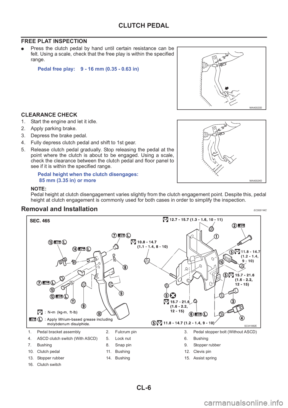
CLUTCH PEDAL
FREE PLAT INSPECTION
●Press the clutch pedal by hand until certain resistance can be
felt. Using a scale, check that the free play is within the specified
range.
CLEARANCE CHECK
1. Start the engine and let it idle.
2. Apply parking brake.
3. Depress the brake pedal.
4. Fully depress clutch pedal and shift to 1st gear.
5. Release clutch pedal gradually. Stop releasing the pedal at the
point where the clutch is about to be engaged. Using a scale,
check the clearance between the clutch pedal and floor panel to
see if it is within the specified range.
NOTE:
Pedal height at clutch disengagement varies slightly from the clutch engagement point. Despite this, pedal
height at clutch engagement is commonly used for both cases in order to simplify the inspection.
Removal and InstallationECS001WC
Pedal free play: 9 - 16 mm (0.35 - 0.63 in)
MAA0023D
Pedal height when the clutch disengages:
85 mm (3.35 in) or more
MAA0024D
1. Pedal bracket assembly 2. Fulcrum pin 3. Pedal stopper bolt (Without ASCD)
4. ASCD clutch switch (With ASCD) 5. Lock nut 6. Bushing
7. Bushing 8. Snap pin 9. Stopper rubber
10. Clutch pedal 11. Bushing 12. Clevis pin
13. Stopper rubber 14. Bushing 15. Assist spring
16. Clutch switch
SCIA1882E
Page 2080 of 3833
AT-2
DTC P0732 A/T 2ND GEAR FUNCTION ................137
Description ............................................................137
Wiring Diagram — AT — 2ND ..............................140
Diagnostic Procedure ...........................................141
Component Inspection ..........................................142
DTC P0733 A/T 3RD GEAR FUNCTION ................143
Description ............................................................143
Wiring Diagram — AT — 3RD ..............................146
Diagnostic Procedure ...........................................147
Component Inspection ..........................................148
DTC P0734 A/T 4TH GEAR FUNCTION ................149
Description ............................................................149
Wiring Diagram — AT — 4TH ...............................152
Diagnostic Procedure ...........................................153
Component Inspection ..........................................156
DTC P0740 TORQUE CONVERTER CLUTCH
SOLENOID VALVE .................................................158
Description ............................................................158
Wiring Diagram — AT — TCV ..............................160
Diagnostic Procedure ...........................................161
Component Inspection ..........................................162
DTC P0745 LINE PRESSURE SOLENOID VALVE .163
Description ............................................................163
Wiring Diagram — AT — LPSV ............................165
Diagnostic Procedure ...........................................166
Component Inspection ..........................................168
DTC P0750 SHIFT SOLENOID VALVE A ...............170
Description ............................................................170
Wiring Diagram — AT — SSV/A ...........................172
Diagnostic Procedure ...........................................173
Component Inspection ..........................................174
DTC P0755 SHIFT SOLENOID VALVE B ...............175
Description ............................................................175
Wiring Diagram — AT — SSV/B ...........................177
Diagnostic Procedure ...........................................178
Component Inspection ..........................................179
DTC P1705 ACCELERATOR PEDAL POSITION
(APP) SENSOR .......................................................180
Description ............................................................180
Wiring Diagram — AT — TPS ..............................182
Diagnostic Procedure ...........................................183
DTC P1760 OVERRUN CLUTCH SOLENOID
VALVE .....................................................................185
Description ............................................................185
Wiring Diagram — AT — OVRCSV ......................187
Diagnostic Procedure ...........................................188
Component Inspection ..........................................189
DTC U1000 CAN COMMUNICATION LINE ...........
.190
Description ............................................................190
On Board Diagnosis Logic ....................................190
DTC Confirmation Procedure ...............................190
Wiring Diagram — AT — CAN ..............................191
Diagnostic Procedure ...........................................192
DTC BATT/FLUID TEMP SEN (A/T FLUID TEMP
SENSOR CIRCUIT AND TCM POWER SOURCE) .193
Description ............................................................193
Wiring Diagram — AT — BA/FTS .........................195
Diagnostic Procedure ...........................................196
Component Inspection ..........................................198DTC VEHICLE SPEED SENSOR MTR ...................199
Description ............................................................199
Wiring Diagram — AT — VSSMTR .......................201
Diagnostic Procedure ............................................202
DTC CONTROL UNIT (RAM), CONTROL UNIT
(ROM) ......................................................................203
Description ............................................................203
Diagnostic Procedure ............................................203
DTC CONTROL UNIT(EEPROM) ...........................205
Description ............................................................205
Diagnostic Procedure ............................................206
TROUBLE DIAGNOSES FOR SYMPTOMS ...........207
Wiring Diagram — AT — NONDTC ......................207
O/D OFF Indicator Lamp Does Not Come On ......209
Engine Cannot Be Started In “P” and “N” Position .211
In “P” Position, Vehicle Moves Forward Or Back-
ward When Pushed ...............................................212
In “N” Position, Vehicle Moves ..............................213
Large Shock. “N” → “R” Position ..........................214
Vehicle Does Not Creep Backward In “R” Position .215
Vehicle Does Not Creep Forward In “D”, “2” Or “1”
Position .................................................................218
Vehicle Cannot Be Started From D
1 .....................220
A/T Does Not Shift: D
1→ D2 Or Does Not Kickdown:
D
4→ D2 ...............................................................
.223
A/T Does Not Shift: D
2→ D3 ................................225
A/T Does Not Shift: D
3→ D4 ................................227
A/T Does Not Perform Lock-up .............................229
A/T Does Not Hold Lock-up Condition ..................230
Lock-up Is Not Released .......................................232
Engine Speed Does Not Return To Idle (Light Brak-
ing D
4→ D3 ) ........................................................233
Vehicle Does Not Start From D
1 ...........................234
A / T D o e s N o t S h i f t : D
4→ D3 , W h e n O v e r d r i v e C o n -
trol Switch “ON” → “OFF” .....................................236
A/T Does Not Shift: D
3→ 22 , W h e n S e l e c t o r L e v e r
“D” → “2” Position .................................................237
A/T Does Not Shift: 2
2→ 11 , When Selector Lever
“2” → “1” Position ..................................................238
Vehicle Does Not Decelerate By Engine Brake ....240
TCM Self-diagnosis Does Not Activate .................241
EXC.F/EURO-OBD
ON BOARD DIAGNOSTIC SYSTEM DESCRIP-
TION ........................................................................247
CONSULT-II ..........................................................247
Diagnostic Procedure Without CONSULT-II .........253
TROUBLE DIAGNOSIS — INTRODUCTION .........258
Introduction ...........................................................258
Work Flow .............................................................262
TROUBLE DIAGNOSIS — BASIC INSPECTION ...264
A/T Fluid Check ....................................................264
Stall Test ................................................................265
Line Pressure Test ................................................268
Road Test ..............................................................269
TROUBLE DIAGNOSIS — GENERAL DESCRIP-
Page 2081 of 3833

AT-3
D
E
F
G
H
I
J
K
L
MA
B
AT TION ........................................................................ 287
Symptom Chart .................................................... 287
TCM Terminals and Reference Value ................... 306
CAN COMMUNICATION ........................................ 309
System Description .............................................. 309
TROUBLE DIAGNOSES FOR SYMPTOMS .......... 310
Wiring Diagram — AT — NONDTC ...................... 310
O/D OFF Indicator Lamp Does Not Come On ..... 312
Engine Cannot Be Started In “P” and “N” Position . 314
In “P” Position, Vehicle Moves Forward Or Back-
ward When Pushed .............................................. 315
In “N” Position, Vehicle Moves ............................. 315
Large Shock. “N” → “R” Position .......................... 317
Vehicle Does Not Creep Backward In “R” Position . 318
Vehicle Does Not Creep Forward In “D”, “2” Or “1”
Position ................................................................ 321
Vehicle Cannot Be Started From D
1 ..................... 323
A/T Does Not Shift: D
1→ D2 Or Does Not Kick down:
D
4→ D2 ............................................................... 326
A/T Does Not Shift: D
2→ D3 ............................... 328
A/T Does Not Shift: D
3→ D4 ............................... 330
A/T Does Not Perform Lock-up ............................ 332
A/T Does Not Hold Lock-up Condition ................. 333
Lock-up Is Not Released ...................................... 335
Engine Speed Does Not Return To Idle (Light Brak-
ing D
4→ D3 ) ....................................................... 336
Vehicle Does Not Start From D
1 ........................... 338
A/T Does Not Shift: D
4→ D3 , When Overdrive Con-
trol Switch “ON” → “OFF” ..................................... 339
A/T Does Not Shift: D
3→ 22 , W h e n S e l e c t o r L e v e r
“D”→ “2” Position ................................................ 340
A/T Does Not Shift: 2
2→ 11 , W h e n S e l e c t o r L e v e r
“2” → “1” Position ................................................. 341
Vehicle Does Not Decelerate By Engine Brake ... 343
TCM Self-diagnosis Does Not Activate ................ 344
ALL
MAIN POWER SUPPLY AND GROUND CIRCUIT . 350
Wiring Diagram — AT — MAIN ............................ 350
Diagnostic Procedure ........................................... 351
VEHICLE SPEED SENSOR·A/T (REVOLUTION
SENSOR) ................................................................ 353
Description ........................................................... 353
Wiring Diagram — AT — VSSA/T ........................ 355
Diagnostic Procedure ........................................... 356
DTC VEHICLE SPEED SENSOR MTR .................. 358
Description ........................................................... 358
Wiring Diagram — AT — VSSMTR ...................... 360
Diagnostic Procedure ........................................... 361
ACCELE RATOR PEDAL POSITION (APP) SEN-
SOR ........................................................................ 362
Description ........................................................... 362
Wiring Diagram — AT — TPS .............................. 364
Diagnostic Procedure ........................................... 365
SHIFT SOLENOID VALVE A .................................. 367
Description ........................................................... 367
Wiring Diagram — AT — SSV/A .......................... 369Diagnostic Procedure ...........................................370
Component Inspection ..........................................371
SHIFT SOLENOID VALVE B ..................................372
Description ............................................................372
Wiring Diagram — AT — SSV/B ...........................374
Diagnostic Procedure ...........................................375
Component Inspection ..........................................376
OVERRUN CLUTCH SOLENOID VALVE ...............377
Description ............................................................377
Wiring Diagram — AT — OVRCSV ......................378
Diagnostic Procedure ...........................................379
Component Inspection ..........................................380
TORQUE CONVERTER CLUTCH SOLENOID
VALVE .....................................................................381
Description ............................................................381
Wiring Diagram — AT — TCV ..............................383
Diagnostic Procedure ...........................................384
Component Inspection ..........................................385
BATT/FLUID TEMP SEN (A/T FLUID TEMP SEN-
SOR CIRCUIT AND TCM POWER SOURCE) .......386
Description ............................................................386
Wiring Diagram — AT — BA/FTS .........................388
Diagnostic Procedure ...........................................389
Component Inspection ..........................................391
ENGINE SPEED SIGNAL .......................................392
Description ............................................................392
Wiring Diagram — AT — ENGSS .........................393
Diagnostic Procedure ...........................................394
LINE PRESSURE SOLENOID VALVE ..................
.396
Description ............................................................396
Wiring Diagram — AT — LPSV ............................398
Diagnostic Procedure ...........................................399
Component Inspection ..........................................401
CAN COMMUNICATION LINE ...............................403
Description ............................................................403
On Board Diagnosis Logic ....................................403
Self-Diagnosis Code Confirmation Procedure ......403
Wiring Diagram — AT — CAN ..............................404
Diagnostic Procedure ...........................................405
A/T SHIFT LOCK SYSTEM ....................................406
Description ............................................................406
Shift Lock System Electrical Parts Location .........406
Wiring Diagram — SHIFT — ................................407
Diagnostic Procedure ...........................................408
KEY INTERLOCK CABLE ......................................412
Components .........................................................412
Removal ...............................................................412
Installation ............................................................413
ON-VEHICLE SERVICE ..........................................414
Control Valve Assembly and Accumulators ..........414
Control Cable Adjustment .....................................416
Park/Neutral Position (PNP) Switch Adjustment ..416
Differential Side Oil Seal Replacement ................417
Revolution Sensor Replacement ..........................417
REMOVAL AND INSTALLATION ...........................418
Removal ...............................................................418
Installation ............................................................419
OVERHAUL ............................................................421
Components .........................................................421
Page 2137 of 3833

TROUBLE DIAGNOSIS — INTRODUCTION
AT-59
[EURO-OBD]
D
E
F
G
H
I
J
K
L
MA
B
AT
4. 4-3. Cruise testAT- 7 4 , "3.
CRUISE
TEST"
AT- 7 8 ,
"Cruise Test
— Part 1"
Part-1
❏ Vehicle Cannot Be Started From D
1 , AT- 2 2 0 , "Vehicle Cannot Be Started From D1" .
❏ A/T Does Not Shift: D
1→ D2 Or Does Not Kickdown: D4→ D2 , AT-223, "A/T Does Not Shift: D1→
D2 Or Does Not Kickdown: D4→ D2" .
❏ A/T Does Not Shift: D
2→ D3 , AT- 2 2 5 , "A/T Does Not Shift: D2→ D3" .
❏ A/T Does Not Shift: D
3→ D4 , AT- 2 2 7 , "A/T Does Not Shift: D3→ D4" .
❏ A/T Does Not Perform Lock-up, AT-229, "
A/T Does Not Perform Lock-up" .
❏ A/T Does Not Hold Lock-up Condition, AT-230, "
A/T Does Not Hold Lock-up Condition" .
❏ Lock-up Is Not Released, AT-232, "
Lock-up Is Not Released" .
❏ Engine Speed Does Not Return To Idle (Light Braking D
4→ D3 ), AT-233, "Engine Speed Does Not
Return To Idle (Light Braking D4→ D3 )" .
Part-2AT- 8 1 ,
"Cruise Test
— Part 2"❏ Vehicle Does Not Start From D1 , AT- 2 3 4 , "Vehicle Does Not Start From D1" .
❏ A/T Does Not Shift: D
1→ D2 Or Does Not Kickdown: D4→ D2 , AT-223, "A/T Does Not Shift: D1→
D2 Or Does Not Kickdown: D4→ D2" .
❏ A/T Does Not Shift: D
2→ D3 , AT- 2 2 5 , "A/T Does Not Shift: D2→ D3" .
❏ A/T Does Not Shift: D
3→ D4 , AT- 2 2 7 , "A/T Does Not Shift: D3→ D4" .
Part-3AT- 8 3 ,
"Cruise Test
— Part 3"❏ A/T Does Not Shift: D4→ D3 When Overdrive Control Switch “ON” → “OFF”, AT-236, "A/T Does Not
Shift: D4→ D3 , When Overdrive Control Switch “ON”→“OFF”" .
❏ Engine Speed Does Not Return To Idle (Engine Brake In D
3 ), AT-233, "Engine Speed Does Not Return
To Idle (Light Braking D4→ D3 )" .
❏ A/T Does Not Shift: D
3→ 22 , When Selector Lever “D” → “2” Position, AT- 2 3 7 , "A/T Does Not Shift:
D3→ 22 , When Selector Lever “D”→“2” Position" .
❏ Engine Speed Does Not Return To Idle (Engine Brake In 2
2 ), AT- 2 3 3 , "Engine Speed Does Not Return
To Idle (Light Braking D4→ D3 )" .
❏ A/T Does Not Shift: 2
2→ 11 , When Selector Lever “2” → “1” Position, AT-238, "A/T Does Not Shift: 22
→ 11 , When Selector Lever “2”→“1” Position" .
❏ Vehicle Does Not Decelerate By Engine Brake, AT- 2 4 0 , "
Vehicle Does Not Decelerate By Engine
Brake" .
❏ TCM Self-diagnosis Does Not Activate (PNP & Overdrive control switches, and throttle position sensor
circuit checks), AT-241, "
TCM Self-diagnosis Does Not Activate" .
❏ SELF-DIAGNOSTIC PROCEDURE/DIAGNOSTIC TROUBLE CODE (DTC) CONFIRMATION PRO-
CEDURE — Mark detected items.
❏ PNP switch, AT- 11 0 , "
DTC P0705 PARK/NEUTRAL POSITION (PNP) SWITCH" .
❏ A/T fluid temperature sensor, AT- 11 6 , "
DTC P0710 A/T FLUID TEMPERATURE SENSOR CIR-
CUIT" .
❏ Vehicle speed sensor·A/T (Revolution sensor), AT- 1 2 2 , "
DTC P0720 VEHICLE SPEED SEN-
SOR·A/T (REVOLUTION SENSOR)" .
❏ Engine speed signal, AT- 1 2 7 , "
DTC P0725 ENGINE SPEED SIGNAL" .
❏ Torque converter clutch solenoid valve, AT-158, "
DTC P0740 TORQUE CONVERTER CLUTCH
SOLENOID VALVE" .
❏ Line pressure solenoid valve, AT-163, "
DTC P0745 LINE PRESSURE SOLENOID VALVE" .
❏ Shift solenoid valve A, AT- 1 7 0 , "
DTC P0750 SHIFT SOLENOID VALVE A" .
❏ Shift solenoid valve B, AT- 1 7 5 , "
DTC P0755 SHIFT SOLENOID VALVE B" .
❏ Accelerator pedal position (App) sensor, AT-180, "
DTC P1705 ACCELERATOR PEDAL POSITION
(APP) SENSOR" .
❏ Overrun clutch solenoid valve, AT- 1 8 5 , "
DTC P1760 OVERRUN CLUTCH SOLENOID VALVE" .
❏ PNP & overdrive control switches, and throttle position sensor, AT-241, "
TCM Self-diagnosis Does
Not Activate" .
❏ A/T fluid temperature sensor and TCM power source, AT-193, "
DTC BATT/FLUID TEMP SEN (A/T
FLUID TEMP SENSOR CIRCUIT AND TCM POWER SOURCE)" .
❏ Vehicle speed sensor·MTR, AT-199, "
DTC VEHICLE SPEED SENSOR MTR" .
❏ CAN communication line, AT- 1 9 0 , "
DTC U1000 CAN COMMUNICATION LINE" .
❏ Control unit (RAM), control unit (ROM), AT-203, "
DTC CONTROL UNIT (RAM), CONTROL UNIT
(ROM)" .
❏ Control unit (EEP ROM), AT-205, "
DTC CONTROL UNIT(EEPROM)" .
❏ Battery
❏ Others