low oil pressure NISSAN X-TRAIL 2003 Electronic Owners Manual
[x] Cancel search | Manufacturer: NISSAN, Model Year: 2003, Model line: X-TRAIL, Model: NISSAN X-TRAIL 2003Pages: 3066, PDF Size: 51.47 MB
Page 2496 of 3066
MA-4
DESCRIPTION
DESCRIPTION
PFP:00000
Pre-delivery Inspection ItemsELS000AK
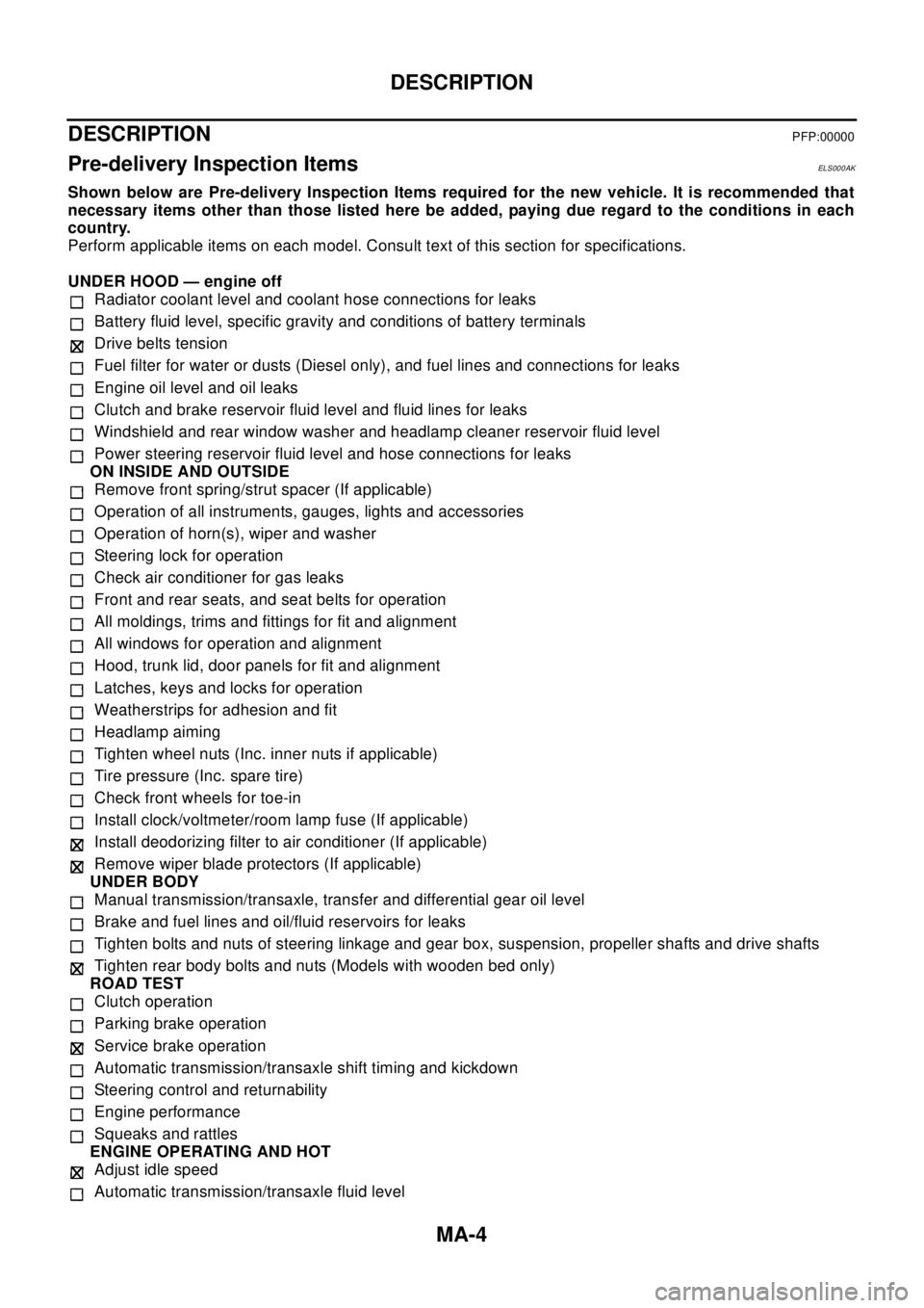
Shown below are Pre-delivery Inspection Items required for the new vehicle. It is recommended that
necessary items other than those listed here be added, paying due regard to the conditions in each
country.
Perform applicable items on each model. Consult text of this section for specifications.
UNDER HOOD — engine off
Radiator coolant level and coolant hose connections for leaks
Battery fluid level, specific gravity and conditions of battery terminals
Drive belts tension
Fuel filter for water or dusts (Diesel only), and fuel lines and connections for leaks
Engine oil level and oil leaks
Clutch and brake reservoir fluid level and fluid lines for leaks
Windshield and rear window washer and headlamp cleaner reservoir fluid level
Power steering reservoir fluid level and hose connections for leaks
ON INSIDE AND OUTSIDE
Remove front spring/strut spacer (If applicable)
Operation of all instruments, gauges, lights and accessories
Operation of horn(s), wiper and washer
Steering lock for operation
Check air conditioner for gas leaks
Front and rear seats, and seat belts for operation
All moldings, trims and fittings for fit and alignment
All windows for operation and alignment
Hood, trunk lid, door panels for fit and alignment
Latches, keys and locks for operation
Weatherstrips for adhesion and fit
Headlamp aiming
Tighten wheel nuts (Inc. inner nuts if applicable)
Tire pressure (Inc. spare tire)
Check front wheels for toe-in
Install clock/voltmeter/room lamp fuse (If applicable)
Install deodorizing filter to air conditioner (If applicable)
Remove wiper blade protectors (If applicable)
UNDER BODY
Manual transmission/transaxle, transfer and differential gear oil level
Brake and fuel lines and oil/fluid reservoirs for leaks
Tighten bolts and nuts of steering linkage and gear box, suspension, propeller shafts and drive shafts
Tighten rear body bolts and nuts (Models with wooden bed only)
ROAD TEST
Clutch operation
Parking brake operation
Service brake operation
Automatic transmission/transaxle shift timing and kickdown
Steering control and returnability
Engine performance
Squeaks and rattles
ENGINE OPERATING AND HOT
Adjust idle speed
Automatic transmission/transaxle fluid level
Page 2530 of 3066
MA-38
CHASSIS AND BODY MAINTENANCE
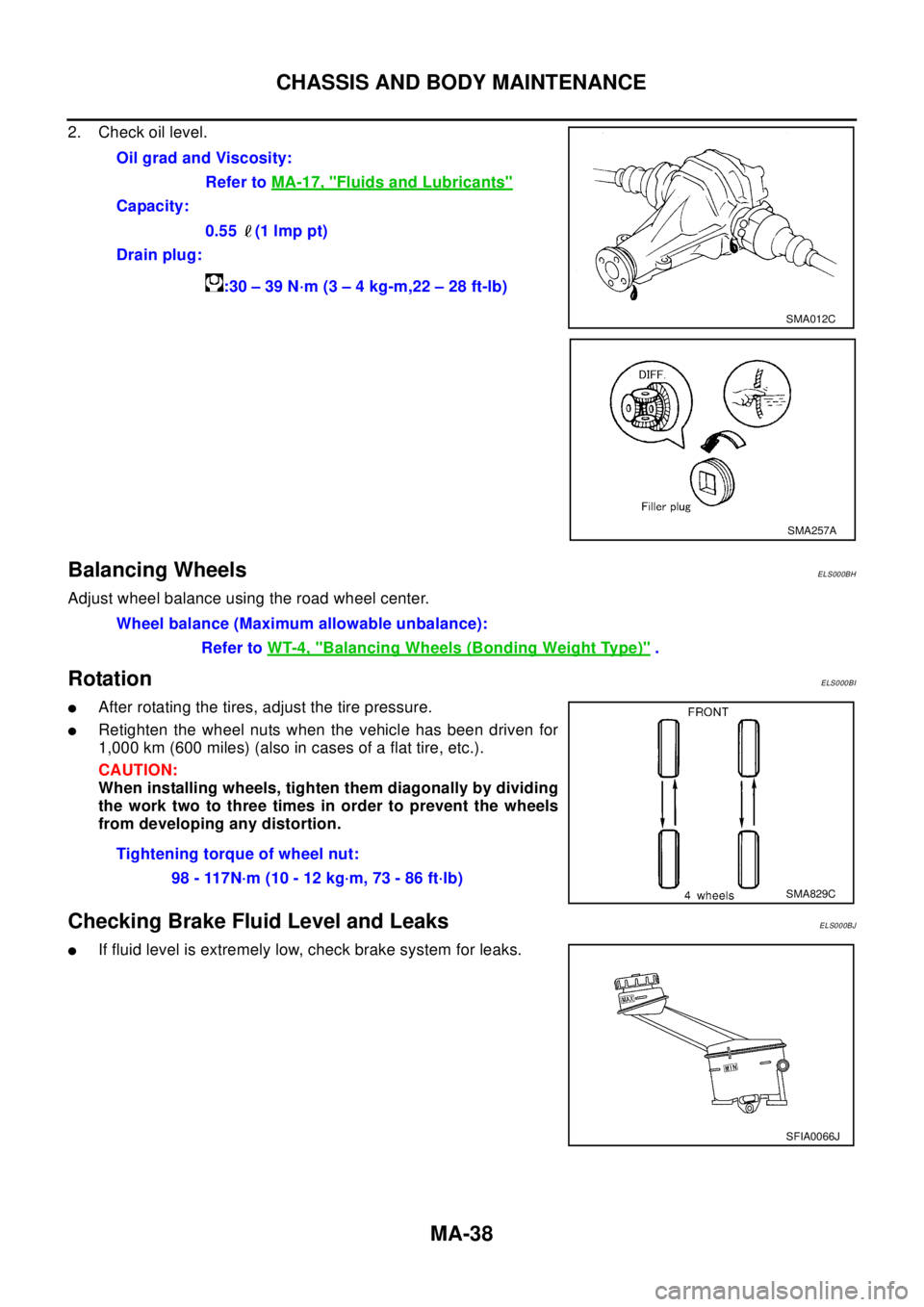
2. Check oil level.
Balancing WheelsELS000BH
Adjust wheel balance using the road wheel center.
RotationELS000BI
lAfter rotating the tires, adjust the tire pressure.
lRetighten the wheel nuts when the vehicle has been driven for
1,000 km (600 miles) (also in cases of a flat tire, etc.).
CAUTION:
When installing wheels, tighten them diagonally by dividing
the work two to three times in order to prevent the wheels
from developing any distortion.
Checking Brake Fluid Level and LeaksELS000BJ
lIf fluid level is extremely low, check brake system for leaks.Oil grad and Viscosity:
Refer toMA-17, "
Fluids and Lubricants"
Capacity:
0.55 (1 lmp pt)
Drain plug:
:30–39N·m(3–4kg-m,22–28ft-lb)
SMA012C
SMA257A
Wheel balance (Maximum allowable unbalance):
Refer toWT-4, "
Balancing Wheels (Bonding Weight Type)".
Tightening torque of wheel nut:
98 - 117N·m (10 - 12 kg·m, 73 - 86 ft·lb)
SMA829C
SFIA0066J
Page 2738 of 3066

PG-62
HARNESS
HO2S1H EC Heated Oxygen Sensor 1 (Front)
HO2S2 EC Heated Oxygen Sensor 1 (Rear)
HO2S2H EC Heated Oxygen Sensor 1 (Rear)
HORN WW Horn
IATS EC Intake Air Temperature Sensor
IATSEN EC Intake Air Temperature Sensor
IGNSYS EC Ignition Signal
ILL LT Illumination
INJECT EC Injector
INT/L LT Map Lamp
IVC EC Intake Valve Timing Control Solenoid Valve
IVC/V EC Intake Valve Timing Control Solenoid Valve
KS EC Knock Sensor (KS)
LOAD EC Electrical Load Signal
LPSV AT Line Pressure Solenoid Valve
MAFS EC MassAirFlowSensor(MAFS)
MAIN EC, AT Main Power Supply and Ground Circuit
METER DI Meter and Gauge
MIL EC Malfunction Indicator Lamp
MIL/DL EC MIL and Data Link Connector
MIRROR GW Door Mirror
MULTI BL Multi-Remote Control System
NATS BL Nissan Anti-Theft System
NONDTC AT Non-Detective Items
OVRCSV AT Overrun Clutch Solenoid Valve
PGC/V EC EVAP Canister Purge Volume Control Solenoid Valve
PHASE EC Camshaft Position Sensor (PHASE)
PNP/SW EC, AT Park/Neutral Position (PNP) Switch
PNPSW1 EC Park/Neutral Position (PNP) Switch
POS EC Crankshaft Position Sensor (CKPS)(POS)
POWER PG Power Supply Routing
PRGVLV EC EVAP Canister Purge Volume Control Solenoid Valve
PRWIRE BL Theft Warning System (Pre-wire)
PS/SEN EC Power Steering Pressure Sensor
PST/SW EC Power Steering Oil Pressure Switch
R/FOG LT Rear Fog Lamp
ROOM/L LT Interior Room Lamp
RP/SEN EC Refrigerant Pressure Sensor
RRO2 EC Heated Oxygen Sensor 2 (Rear)
RRO2/H EC Heated Oxygen Sensor 2 Heater (Rear)
S/LOCK BL Super Lock
S/SIG EC Start Signal
SCTC/V EC Suction Control Valve
SHIFT AT A/T Shift Lock System
SROOF BL Sunroof
SRS SRS Supplemental Restraint System (SRS)
SSV/A AT Shift Solenoid Valve A
SSV/B AT Shift Solenoid Valve B
START SC Starting System
STOP/L LT Stop Lamp
T/MTR EC Throttle Control Motor
TAIL/L LT Parking, License and Tail Lamps
Page 2761 of 3066
PS-1
POWER STEERING SYSTEM
G STEERING
CONTENTS
C
D
E
F
H
I
J
K
L
M
SECTION
A
B
PS
POWER STEERING SYSTEM
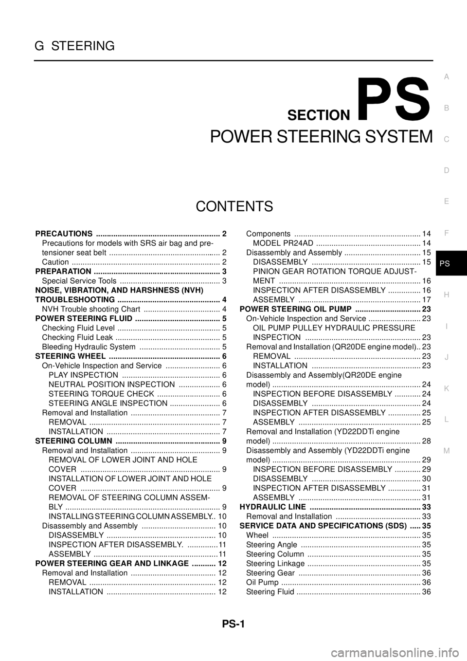
PRECAUTIONS .......................................................... 2
Precautions for models with SRS air bag and pre-
tensioner seat belt .................................................... 2
Caution ..................................................................... 2
PREPARATION ........................................................... 3
Special Service Tools ............................................... 3
NOISE, VIBRATION, AND HARSHNESS (NVH)
TROUBLESHOOTING ................................................ 4
NVH Trouble shooting Chart .................................... 4
POWER STEERING FLUID ........................................ 5
Checking Fluid Level ................................................ 5
Checking Fluid Leak ................................................. 5
Bleeding Hydraulic System ...................................... 5
STEERING WHEEL .................................................... 6
On-Vehicle Inspection and Service .......................... 6
PLAY INSPECTION .............................................. 6
NEUTRAL POSITION INSPECTION .................... 6
STEERING TORQUE CHECK .............................. 6
STEERING ANGLE INSPECTION ........................ 6
Removal and Installation .......................................... 7
REMOVAL ............................................................. 7
INSTALLATION ..................................................... 7
STEERING COLUMN ................................................. 9
Removal and Installation .......................................... 9
REMOVAL OF LOWER JOINT AND HOLE
COVER ................................................................. 9
INSTALLATION OF LOWER JOINT AND HOLE
COVER ................................................................. 9
REMOVAL OF STEERING COLUMN ASSEM-
BLY ........................................................................ 9
INSTALLING STEERING COLUMN ASSEMBLY... 10
Disassembly and Assembly ................................... 10
DISASSEMBLY ................................................... 10
INSPECTION AFTER DISASSEMBLY. ...............11
ASSEMBLY ..........................................................11
POWER STEERING GEAR AND LINKAGE ............ 12
Removal and Installation ........................................ 12
REMOVAL ........................................................... 12
INSTALLATION ................................................... 12Components ........................................................... 14
MODEL PR24AD ................................................. 14
Disassembly and Assembly .................................... 15
DISASSEMBLY ................................................... 15
PINION GEAR ROTATION TORQUE ADJUST-
MENT .................................................................. 16
INSPECTION AFTER DISASSEMBLY ................ 16
ASSEMBLY ......................................................... 17
POWER STEERING OIL PUMP ............................... 23
On-Vehicle Inspection and Service ......................... 23
OIL PUMP PULLEY HYDRAULIC PRESSURE
INSPECTION ...................................................... 23
Removal and Installation (QR20DE engine model)... 23
REMOVAL ........................................................... 23
INSTALLATION ................................................... 23
Disassembly and Assembly(QR20DE engine
model) ..................................................................... 24
INSPECTION BEFORE DISASSEMBLY ............. 24
DISASSEMBLY ................................................... 24
INSPECTION AFTER DISASSEMBLY ................ 25
ASSEMBLY ......................................................... 25
Removal and Installation (YD22DDTi engine
model) ..................................................................... 28
Disassembly and Assembly (YD22DDTi engine
model) ..................................................................... 29
INSPECTION BEFORE DISASSEMBLY ............. 29
DISASSEMBLY ................................................... 30
INSPECTION AFTER DISASSEMBLY ................ 31
ASSEMBLY ......................................................... 31
HYDRAULIC LINE .................................................... 33
Removal and Installation ........................................ 33
SERVICE DATA AND SPECIFICATIONS (SDS) ...... 35
Wheel ..................................................................... 35
Steering Angle ........................................................ 35
Steering Column ..................................................... 35
Steering Linkage ..................................................... 35
Steering Gear ......................................................... 36
Oil Pump ................................................................. 36
Steering Fluid .......................................................... 36
Page 2766 of 3066
PS-6
STEERING WHEEL
STEERING WHEEL
PFP:48430
On-Vehicle Inspection and ServiceEGS0004E
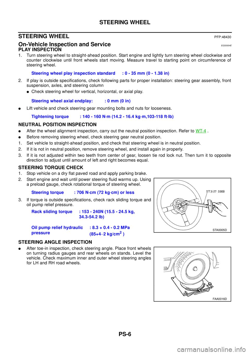
PLAY INSPECTION
1. Turn steering wheel to straight-ahead position. Start engine and lightly turn steering wheel clockwise and
counter clockwise until front wheels start moving. Measure travel to starting point on circumference of
steering wheel.
2. If play is outside specifications, check following parts for proper installation: steering gear assembly, front
suspension, axles, and steering column
lCheck steering wheel for vertical, horizontal, or axial play.
lLift vehicle and check steering gear mounting bolts and nuts for looseness.
NEUTRAL POSITION INSPECTION
lAfter the wheel alignment inspection, carry out the neutral position inspection. Refer toWT-4.
lBefore removing steering wheel, check steering gear neutral position.
1. Set vehicle to straight-ahead position, and check that steering wheel is in neutral position.
2. If it is not in neutral position, remove steering wheel, and install again in properly.
3. If it is not adjusted within two teeth from center of gear, loosen tie rod lock nut. Then turn it to opposite
direction to adjust until amount of left and right becomes equal.
STEERING TORQUE CHECK
1. Stop vehicle on a dry flat paved road and apply parking brake.
2. Start engine and wait until power steering fluid warms up. Using
a preload gauge, check rotational torque of steering wheel.
3. If torque is outside specifications, check rack sliding torque and
oil pump relief pressure.
STEERING ANGLE INSPECTION
lAfter toe-in inspection, check steering angle. Place front wheels
on turning radius gauges and rear wheels on stands. Level the
vehicle. Check maximum inner and outer wheel steering angles
for LH and RH road wheels.Steering wheel play inspection standard : 0 - 35 mm (0 - 1.38 in)
Steering wheel axial endplay: : 0 mm (0 in)
Tightening torque : 140 - 160 N·m (14.2 - 16.4 kg·m,103-118 ft·lb)
Steering torque : 706 N·cm (72 kg·cm) or less
Rack sliding torque : 153 - 240N (15.5 - 24.5 kg,
34.3-54.2 lb)
Oil pump relief hydraulic
pressure: 8.3 + 0.4 - 0.2 MPa
(85+4-2kg/cm
2)
STA0005D
FAA0016D
Page 2783 of 3066
POWER STEERING OIL PUMP
PS-23
C
D
E
F
H
I
J
K
L
MA
B
PS
POWER STEERING OIL PUMPPFP:49110
On-Vehicle Inspection and ServiceEGS000AF
OIL PUMP PULLEY HYDRAULIC PRESSURE INSPECTION
Before starting following procedure, check tension of belt.
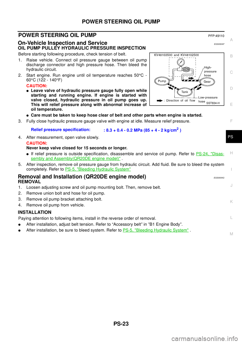
1. Raise vehicle. Connect oil pressure gauge between oil pump
discharge connector and high pressure hose. Then bleed the
hydraulic circuit.
2. Start engine. Run engine until oil temperature reaches 50°C-
60°C (122 - 140°F)
CAUTION:
lLeave valve of hydraulic pressure gauge fully open while
starting and running engine. If engine is started with
valve closed, hydraulic pressure in oil pump goes up.
This will relief pressure along with abnormal increase of
oil temperature.
lCare must be taken to keep hose clear of belt and other parts when engine is started.
3. Fully close hydraulic pressure gauge valve with engine at idle. Measure relief pressure.
4. After measurement, open valve slowly.
CAUTION:
Never keep valve closed for 15 seconds or longer.
lIf relief pressure is outside specification, disassemble and service oil pump. Refer toPS-24, "Disas-
sembly and Assembly(QR20DE engine model)".
5. After inspection, remove oil pressure gauge from hydraulic circuit. Add fluid. Be sure to bleed the system
completely. Refer toPS-5, "
Bleeding Hydraulic System"
Removal and Installation (QR20DE engine model)EGS000AG
REMOVAL
1. Loosen adjusting screw and oil pump mounting bolt. Then, remove belt.
2. Remove union bolt and hose for oil pump.
3. Remove oil pump bracket attaching bolt.
4. Remove oil pump from vehicle.
INSTALLATION
Paying attention to following items, install in the reverse order of removal.
lAfter installation, adjust belt tension. Refer to “Accessory belt” in ”B1 Engine Body”.
lAfter installation, be sure to bleed system. Refer toPS-5, "Bleeding Hydraulic System". Relief pressure specification:
: 8.3 + 0.4 - 0.2 MPa (85 + 4 - 2 kg/cm
2)
SST834-H
Page 2796 of 3066
PS-36
SERVICE DATA AND SPECIFICATIONS (SDS)
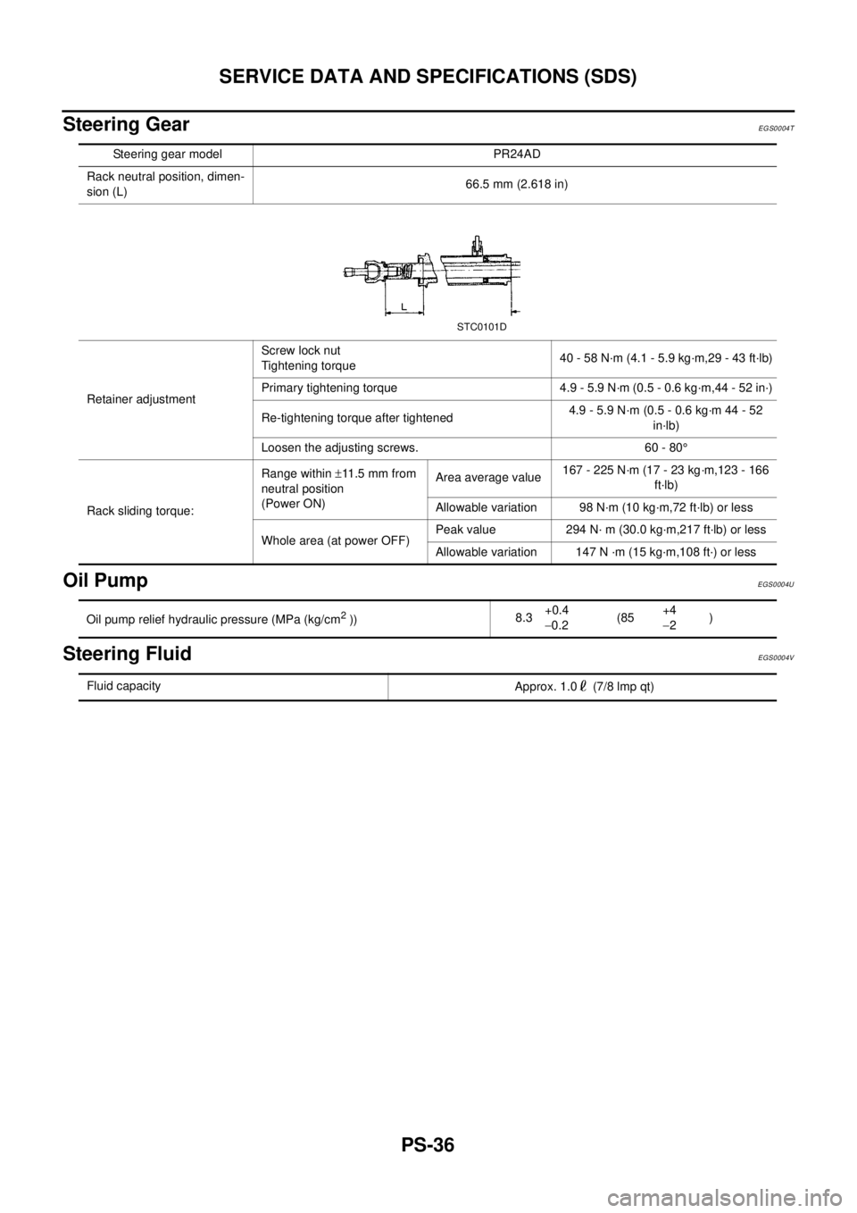
Steering Gear
EGS0004T
Oil PumpEGS0004U
Steering FluidEGS0004V
Steering gear model PR24AD
Rack neutral position, dimen-
sion (L)66.5 mm (2.618 in)
Retainer adjustmentScrew lock nut
Tightening torque40 - 58 N·m (4.1 - 5.9 kg·m,29 - 43 ft·lb)
Primary tightening torque 4.9 - 5.9 N·m (0.5 - 0.6 kg·m,44 - 52 in·)
Re-tightening torque after tightened4.9 - 5.9 N·m (0.5 - 0.6 kg·m 44 - 52
in·lb)
Loosen the adjusting screws. 60 - 80°
Rack sliding torque:Range within±11 .5 m m f r o m
neutral position
(Power ON)Area average value167 - 225 N·m (17 - 23 kg·m,123 - 166
ft·lb)
Allowable variation 98 N·m (10 kg·m,72 ft·lb) or less
Whole area (at power OFF)Peak value 294 N· m (30.0 kg·m,217 ft·lb) or less
Allowable variation 147 N ·m (15 kg·m,108 ft·) or less
STC0101D
Oil pump relief hydraulic pressure (MPa (kg/cm2))8.3+0.4
-0.2(85+4
-2)
Fluid capacity
Approx. 1.0 (7/8 lmp qt)
Page 2842 of 3066
RFD-20
REAR FINAL DRIVE ASSEMBLY
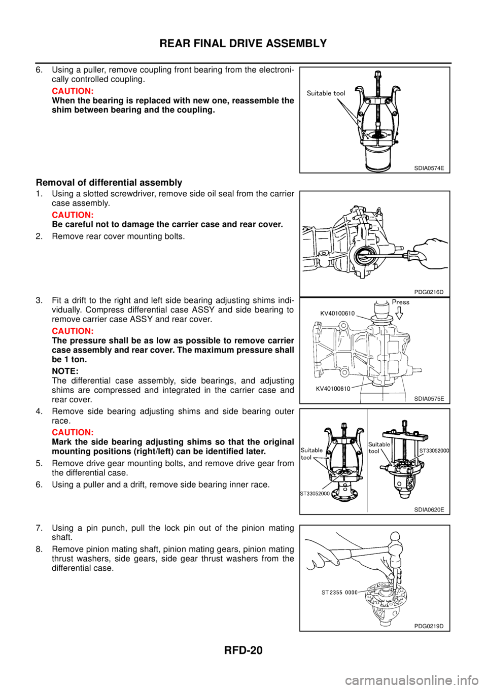
6. Using a puller, remove coupling front bearing from the electroni-
cally controlled coupling.
CAUTION:
When the bearing is replaced with new one, reassemble the
shim between bearing and the coupling.
Removal of differential assembly
1. Using a slotted screwdriver, remove side oil seal from the carrier
case assembly.
CAUTION:
Be careful not to damage the carrier case and rear cover.
2. Remove rear cover mounting bolts.
3. Fit a drift to the right and left side bearing adjusting shims indi-
vidually. Compress differential case ASSY and side bearing to
remove carrier case ASSY and rear cover.
CAUTION:
The pressure shall be as low as possible to remove carrier
case assembly and rear cover. The maximum pressure shall
be 1 ton.
NOTE:
The differential case assembly, side bearings, and adjusting
shims are compressed and integrated in the carrier case and
rear cover.
4. Remove side bearing adjusting shims and side bearing outer
race.
CAUTION:
Mark the side bearing adjusting shims so that the original
mounting positions (right/left) can be identified later.
5. Remove drive gear mounting bolts, and remove drive gear from
the differential case.
6. Using a puller and a drift, remove side bearing inner race.
7. Using a pin punch, pull the lock pin out of the pinion mating
shaft.
8. Remove pinion mating shaft, pinion mating gears, pinion mating
thrust washers, side gears, side gear thrust washers from the
differential case.
SDIA0574E
PDG0216D
SDIA0575E
SDIA0620E
PDG0219D
Page 2848 of 3066
RFD-26
REAR FINAL DRIVE ASSEMBLY
9. Apply differential oil to the side bearings, and assemble new side bearing adjusting shims (2 pieces for
one side) with the same thickness as the ones installed prior to disassembly or re-install the old ones, with
a side bearing outer race to the differential case.
If the side bearing adjusting shims have been already selected, use them.
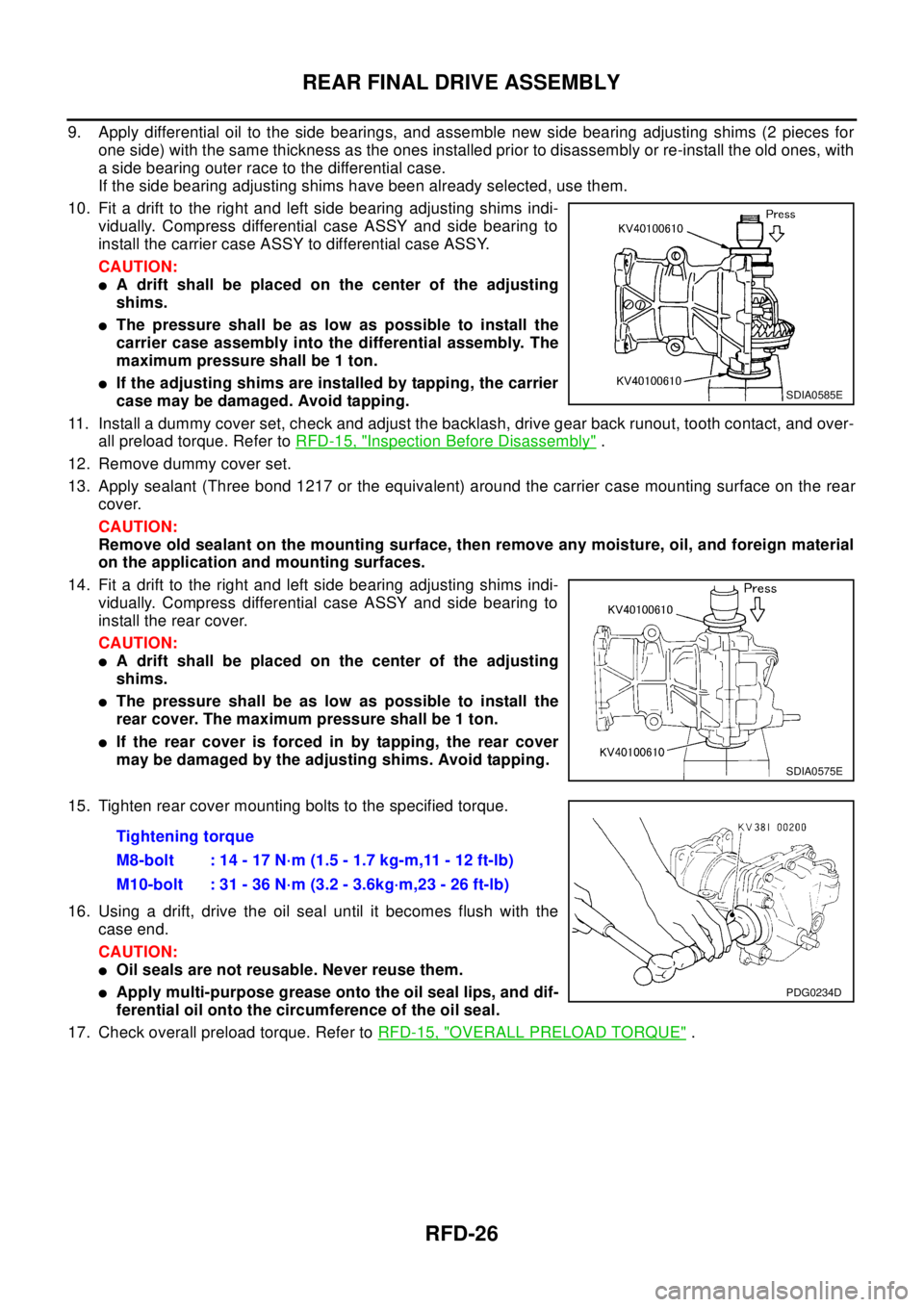
10. Fit a drift to the right and left side bearing adjusting shims indi-
vidually. Compress differential case ASSY and side bearing to
install the carrier case ASSY to differential case ASSY.
CAUTION:
lA drift shall be placed on the center of the adjusting
shims.
lThepressureshallbeaslowaspossibletoinstallthe
carrier case assembly into the differential assembly. The
maximum pressure shall be 1 ton.
lIf the adjusting shims are installed by tapping, the carrier
case may be damaged. Avoid tapping.
11. Install a dummy cover set, check and adjust the backlash, drive gear back runout, tooth contact, and over-
all preload torque. Refer toRFD-15, "
Inspection Before Disassembly".
12. Remove dummy cover set.
13. Apply sealant (Three bond 1217 or the equivalent) around the carrier case mounting surface on the rear
cover.
CAUTION:
Remove old sealant on the mounting surface, then remove any moisture, oil, and foreign material
on the application and mounting surfaces.
14. Fit a drift to the right and left side bearing adjusting shims indi-
vidually. Compress differential case ASSY and side bearing to
install the rear cover.
CAUTION:
lA drift shall be placed on the center of the adjusting
shims.
lThepressureshallbeaslowaspossibletoinstallthe
rear cover. The maximum pressure shall be 1 ton.
lIf the rear cover is forced in by tapping, the rear cover
may be damaged by the adjusting shims. Avoid tapping.
15. Tighten rear cover mounting bolts to the specified torque.
16. Using a drift, drive the oil seal until it becomes flush with the
case end.
CAUTION:
lOil seals are not reusable. Never reuse them.
lApply multi-purpose grease onto the oil seal lips, and dif-
ferential oil onto the circumference of the oil seal.
17. Check overall preload torque. Refer toRFD-15, "
OVERALL PRELOAD TORQUE".
SDIA0585E
SDIA0575E
Tightening torque
M8-bolt : 14 - 17 N·m (1.5 - 1.7 kg-m,11 - 12 ft-lb)
M10-bolt : 31 - 36 N·m (3.2 - 3.6kg·m,23 - 26 ft-lb)
PDG0234D
Page 2858 of 3066
RSU-6
REAR SUSPENSION ASSEMBLY
On-Vehicle Inspection and Service
EES0007F
Check axle and suspension parts for excessive play, wear, and damage.
lMove rear wheels (RH/LH) to check abnormal free play.
lRetighten all nuts and bolts to the specified torque.
lCheck strut for oil leakage and damage.
Wheel AlignmentEES0007G
DESCRIPTION
lMeasure wheel alignment under unladen conditions. “Unladen conditions” means that fuel, coolant, and
lubricant are full. However, spare tire, jack, and hand tools should be unloaded.
PRELIMINARY INSPECTION
1. Check the tires for improper air pressure and wear.
2. Check road wheels for runout.
3. Check wheel bearing axial endplay.
4. Check strut operation.
5. Check each mounting point of axle and suspension for looseness and deformation.
6. Check each link and arm for cracks, deformation, and other damage.
7. Check the vehicle posture.
CAMBER
Camber is preset at factory and cannot be adjusted.
lIf the camber is not within specification, inspect and replace any damaged or worn rear suspension parts.
TOE-IN
Measure toe-in using the following procedure.
lAlways perform following procedure on a flat surface.
lMake sure that no person is in front of the vehicle before push-
ing it.
1. Bounce rear of vehicle up and down to stabilize the posture.
2. Push the vehicle straight ahead about 5 m (16 ft).
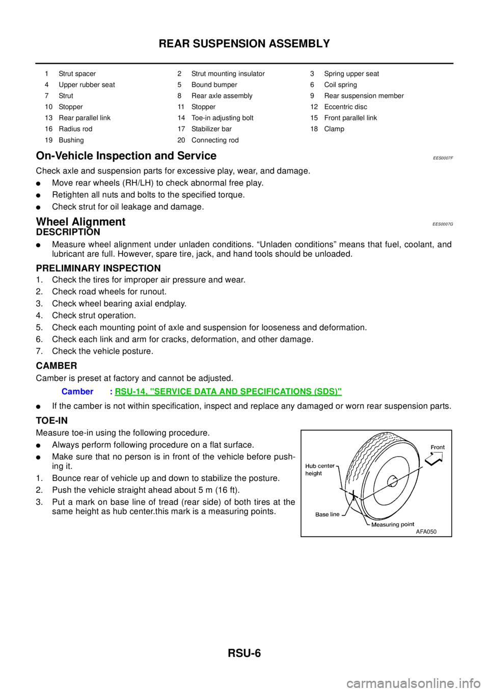
3. Put a mark on base line of tread (rear side) of both tires at the
same height as hub center.this mark is a measuring points.
1 Strut spacer 2 Strut mounting insulator 3 Spring upper seat
4 Upper rubber seat 5 Bound bumper 6 Coil spring
7 Strut 8 Rear axle assembly 9 Rear suspension member
10 Stopper 11 Stopper 12 Eccentric disc
13 Rear parallel link 14 Toe-in adjusting bolt 15 Front parallel link
16 Radius rod 17 Stabilizer bar 18 Clamp
19 Bushing 20 Connecting rod
Camber :RSU-14, "SERVICE DATA AND SPECIFICATIONS (SDS)"
AFA050