wheel bolts NISSAN X-TRAIL 2003 Electronic Repair Manual
[x] Cancel search | Manufacturer: NISSAN, Model Year: 2003, Model line: X-TRAIL, Model: NISSAN X-TRAIL 2003Pages: 3066, PDF Size: 51.47 MB
Page 74 of 3066
![NISSAN X-TRAIL 2003 Electronic Repair Manual AT-68
[EURO-OBD]
TROUBLE DIAGNOSIS — BASIC INSPECTION
Line Pressure Test
ECS004QS
LINE PRESSURE TEST PORTS
Location of line pressure test ports are shown in the illustration.
lAlways replace pressur](/img/5/57402/w960_57402-73.png "NISSAN X-TRAIL 2003 Electronic Repair Manual AT-68
[EURO-OBD]
TROUBLE DIAGNOSIS — BASIC INSPECTION
Line Pressure Test
ECS004QS
LINE PRESSURE TEST PORTS
Location of line pressure test ports are shown in the illustration.
lAlways replace pressur")
AT-68
[EURO-OBD]
TROUBLE DIAGNOSIS — BASIC INSPECTION
Line Pressure Test
ECS004QS
LINE PRESSURE TEST PORTS
Location of line pressure test ports are shown in the illustration.
lAlways replace pressure plugs as they are self-sealing
bolts.
LINE PRESSURE TEST PROCEDURE
1. Check A/T fluid and engine oil levels. If necessary, add fluid or
oil.
2. Drive vehicle for approx. 10 minutes or until engine oil and ATF
reach operating temperature.
3. Install pressure gauge to corresponding line pressure port.
4. Set parking brake and block wheels.
lContinue to depress brake pedal fully while line pressure
test is being performed at stall speed.
SCIA0709E
ATF operating temperature: 50 - 80°C (122 -176°F)
SAT647B
UAT008
UAT008
Page 296 of 3066
![NISSAN X-TRAIL 2003 Electronic Repair Manual AT-290
[EXC.F/EURO-OBD]
TROUBLE DIAGNOSIS — BASIC INSPECTION
Line Pressure Test
ECS004VT
LINE PRESSURE TEST PORTS
Location of line pressure test ports are shown in the illustration.
lAlways replace](/img/5/57402/w960_57402-295.png "NISSAN X-TRAIL 2003 Electronic Repair Manual AT-290
[EXC.F/EURO-OBD]
TROUBLE DIAGNOSIS — BASIC INSPECTION
Line Pressure Test
ECS004VT
LINE PRESSURE TEST PORTS
Location of line pressure test ports are shown in the illustration.
lAlways replace")
AT-290
[EXC.F/EURO-OBD]
TROUBLE DIAGNOSIS — BASIC INSPECTION
Line Pressure Test
ECS004VT
LINE PRESSURE TEST PORTS
Location of line pressure test ports are shown in the illustration.
lAlways replace pressure plugs as they are self-sealing
bolts.
LINE PRESSURE TEST PROCEDURE
1. Check A/T fluid and engine oil levels. If necessary, add fluid or
oil.
2. Drive vehicle for approx. 10 minutes or until engine oil and ATF
reach operating temperature.
3. Install pressure gauge to corresponding line pressure port.
4. Set parking brake and block wheels.
lContinue to depress brake pedal fully while line pressure
test is being performed at stall speed.
SCIA0709E
ATF operating temperature: 50 - 80°C (122 -176°F)
SAT647B
UAT008
UAT008
Page 465 of 3066
![NISSAN X-TRAIL 2003 Electronic Repair Manual REMOVAL AND INSTALLATION
AT-459
[ALL]
D
E
F
G
H
I
J
K
L
MA
B
AT
12. Remove center member, engine insulator and engine mounting
bracket.
lTighten center member fixing bolts to specified torque, Refer
t](/img/5/57402/w960_57402-464.png "NISSAN X-TRAIL 2003 Electronic Repair Manual REMOVAL AND INSTALLATION
AT-459
[ALL]
D
E
F
G
H
I
J
K
L
MA
B
AT
12. Remove center member, engine insulator and engine mounting
bracket.
lTighten center member fixing bolts to specified torque, Refer
t")
REMOVAL AND INSTALLATION
AT-459
[ALL]
D
E
F
G
H
I
J
K
L
MA
B
AT
12. Remove center member, engine insulator and engine mounting
bracket.
lTighten center member fixing bolts to specified torque, Refer
toEM-61, "
ENGINE ASSEMBLY".
13. Remove suspension member. Refer toFSU-12, "
FRONT SUS-
PENSION MEMBER".
14. Remove dust cover from converter housing.
Rotate crankshaft to gain access to securing bolts.
15. Remove securing bolts between drive plate and torque con-
verter. when crank shaft rotates, turn to right at the front side of
engine.
16. Support engine with a jack.
17. Remove bolts fixing transaxle to engine.
18. Lower transaxle while supporting it with a jack.
InstallationECS004ND
1. Check drive plate runout.
CAUTION:
Do not allow any magnetic materials to contact the ring
gear teeth.
lIf this runout is out of allowance, replace drive plate with ring
gear.
2. When connecting torque converter to transaxle, measure dis-
tance “A” to be certain that they are correctly assembled.
SCIA0794E
AAT259A
Maximum allowable runout :
Refer to EM-´´, “FLYWHEEL/DRIVE PLATE RUNOUT”.
SAT977H
Distance “A”: 19 mm (0.626 in) or more
SAT573D
Page 845 of 3066
BRAKE PIPING AND HOSE
BR-11
C
D
E
G
H
I
J
K
L
MA
B
BR
BRAKE PIPING AND HOSEPFP:46210
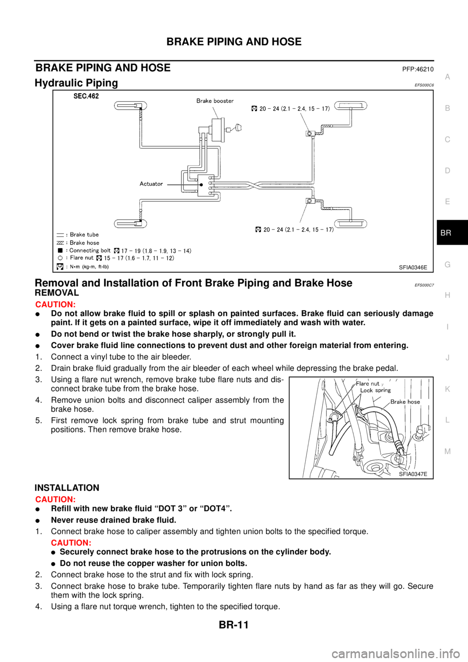
Hydraulic PipingEFS000C6
Removal and Installation of Front Brake Piping and Brake HoseEFS000C7
REMOVAL
CAUTION:
lDo not allow brake fluid to spill or splash on painted surfaces. Brake fluid can seriously damage
paint. If it gets on a painted surface, wipe it off immediately and wash with water.
lDo not bend or twist the brake hose sharply, or strongly pull it.
lCover brake fluid line connections to prevent dust and other foreign material from entering.
1. Connect a vinyl tube to the air bleeder.
2. Drain brake fluid gradually from the air bleeder of each wheel while depressing the brake pedal.
3. Using a flare nut wrench, remove brake tube flare nuts and dis-
connect brake tube from the brake hose.
4. Remove union bolts and disconnect caliper assembly from the
brake hose.
5. First remove lock spring from brake tube and strut mounting
positions. Then remove brake hose.
INSTALLATION
CAUTION:
lRefill with new brake fluid “DOT 3” or “DOT4”.
lNever reuse drained brake fluid.
1. Connect brake hose to caliper assembly and tighten union bolts to the specified torque.
CAUTION:
lSecurely connect brake hose to the protrusions on the cylinder body.
lDo not reuse the copper washer for union bolts.
2. Connect brake hose to the strut and fix with lock spring.
3. Connect brake hose to brake tube. Temporarily tighten flare nuts by hand as far as they will go. Secure
them with the lock spring.
4. Using a flare nut torque wrench, tighten to the specified torque.
SFIA0346E
SFIA0347E
Page 846 of 3066
BR-12
BRAKE PIPING AND HOSE
5. Refill brake fluid until new brake fluid comes out of each air bleeder.
6. Afterwards, bleed air.
Removal and Installation of Rear Brake Piping and Brake HoseEFS000C8
REMOVAL
CAUTION:
lDo not allow brake fluid to spill or splash on painted surfaces. Brake fluid can seriously damage
paint. If it gets on a painted surface, wipe it off immediately and wash with water.
lDo not bend or twist the brake hose sharply, or strongly pull it.
lCover brake fluid line connections to prevent dust and other foreign material from entering.
1. Connect a vinyl tube to the air bleeder.
2. Drain brake fluid gradually from the air bleeder of each wheel while depressing the brake pedal.
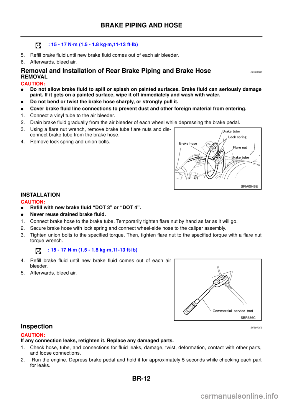
3. Using a flare nut wrench, remove brake tube flare nuts and dis-
connect brake tube from the brake hose.
4. Remove lock spring and union bolts.
INSTALLATION
CAUTION:
lRefill with new brake fluid “DOT 3” or “DOT 4”.
lNever reuse drained brake fluid.
1. Connect brake hose to the brake tube. Temporarily tighten flare nut by hand as far as it will go.
2. Secure brake hose with lock spring and connect wheel-side hose to the caliper assembly.
3. Tighten union bolts to the specified torque. Then, tighten flare nut to the specified torque with a flare nut
torque wrench.
4. Refill brake fluid until new brake fluid comes out of each air
bleeder.
5. Afterwards, bleed air.
InspectionEFS000C9
CAUTION:
If any connection leaks, retighten it. Replace any damaged parts.
1. Check hose, tube, and connections for fluid leaks, damage, twist, deformation, contact with other parts,
and loose connections.
2. Run the engine. Depress brake pedal and hold it for approximately 5 seconds while checking each part
for leaks.:15-17N·m(1.5-1.8kg·m,11-13ft·lb)
SFIA0046E
: 15 - 17 N·m (1.5 - 1.8 kg·m,11-13 ft·lb)
SBR686C
Page 861 of 3066
REAR DISC BRAKE
BR-27
C
D
E
G
H
I
J
K
L
MA
B
BR
REAR DISC BRAKEPFP:44000
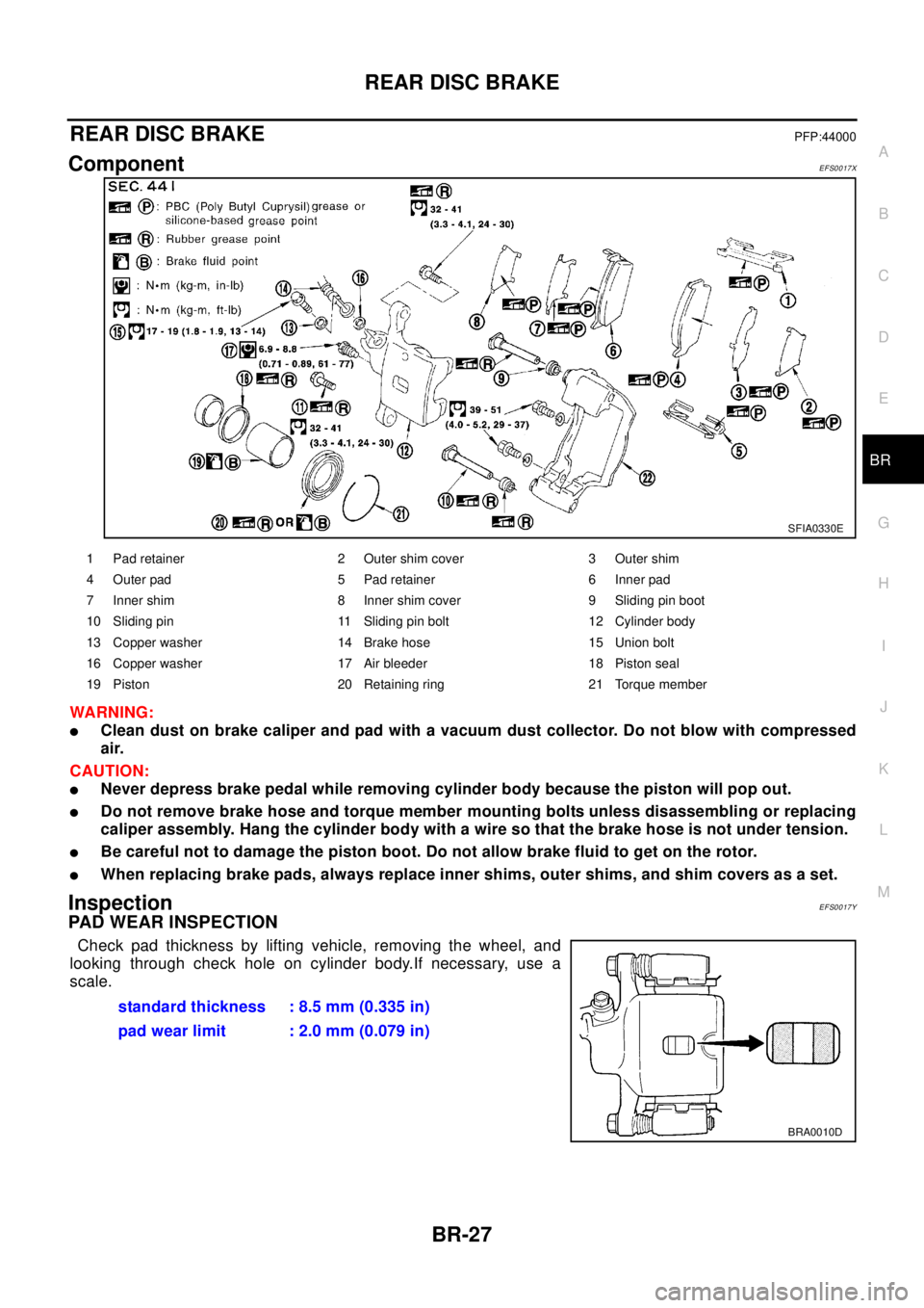
ComponentEFS0017X
WA RN ING:
lClean dust on brake caliper and pad with a vacuum dust collector. Do not blow with compressed
air.
CAUTION:
lNever depress brake pedal while removing cylinder body because the piston will pop out.
lDo not remove brake hose and torque member mounting bolts unless disassembling or replacing
caliper assembly. Hang the cylinder body with a wire so that the brake hose is not under tension.
lBe careful not to damage the piston boot. Do not allow brake fluid to get on the rotor.
lWhen replacing brake pads, always replace inner shims, outer shims, and shim covers as a set.
InspectionEFS0017Y
PAD WEAR INSPECTION
Check pad thickness by lifting vehicle, removing the wheel, and
looking through check hole on cylinder body.If necessary, use a
scale.
SFIA0330E
1 Pad retainer 2 Outer shim cover 3 Outer shim
4 Outer pad 5 Pad retainer 6 Inner pad
7 Inner shim 8 Inner shim cover 9 Sliding pin boot
10 Sliding pin 11 Sliding pin bolt 12 Cylinder body
13 Copper washer 14 Brake hose 15 Union bolt
16 Copper washer 17 Air bleeder 18 Piston seal
19 Piston 20 Retaining ring 21 Torque member
standard thickness : 8.5 mm (0.335 in)
pad wear limit : 2.0 mm (0.079 in)
BRA0010D
Page 916 of 3066
![NISSAN X-TRAIL 2003 Electronic Repair Manual BRC-48
[4WD/ABS]
WHEEL SENSORS
WHEEL SENSORS
PFP:47910
Removal and InstallationEFS001C1
CAUTION:
lBe careful not to damage sensor edge and rotor tooth. Before removing front or rear wheel hub,
remove](/img/5/57402/w960_57402-915.png "NISSAN X-TRAIL 2003 Electronic Repair Manual BRC-48
[4WD/ABS]
WHEEL SENSORS
WHEEL SENSORS
PFP:47910
Removal and InstallationEFS001C1
CAUTION:
lBe careful not to damage sensor edge and rotor tooth. Before removing front or rear wheel hub,
remove")
BRC-48
[4WD/ABS]
WHEEL SENSORS
WHEEL SENSORS
PFP:47910
Removal and InstallationEFS001C1
CAUTION:
lBe careful not to damage sensor edge and rotor tooth. Before removing front or rear wheel hub,
remove wheel speed sensor to avoid sensor wiring damage. Otherwise, sensor may be deacti-
vated.
lWhen removing sensor, avoid rotating it as much as possible. Do not forcibly pull sensor harness.
lWhen installing, check sensor pick-up and mounting hole for foreign material such as iron chips.
Check no foreign material has been caught in sensor rotor. Remove any foreign material found.
Tighten mounting bolts and nuts to the specified torque.
SFIA0042E
Page 987 of 3066
![NISSAN X-TRAIL 2003 Electronic Repair Manual WHEEL SPEED SENSORS
BRC-119
[ESP/TCS/ABS]
C
D
E
G
H
I
J
K
L
MA
B
BRC
WHEEL SPEED SENSORSPFP:47910
Removal and InstallationEFS001CD
CAUTION:
lBe careful not to damage sensor edge and rotor tooth. Befor](/img/5/57402/w960_57402-986.png "NISSAN X-TRAIL 2003 Electronic Repair Manual WHEEL SPEED SENSORS
BRC-119
[ESP/TCS/ABS]
C
D
E
G
H
I
J
K
L
MA
B
BRC
WHEEL SPEED SENSORSPFP:47910
Removal and InstallationEFS001CD
CAUTION:
lBe careful not to damage sensor edge and rotor tooth. Befor")
WHEEL SPEED SENSORS
BRC-119
[ESP/TCS/ABS]
C
D
E
G
H
I
J
K
L
MA
B
BRC
WHEEL SPEED SENSORSPFP:47910
Removal and InstallationEFS001CD
CAUTION:
lBe careful not to damage sensor edge and rotor tooth. Before removing front or rear wheel hub,
remove wheel speed sensor to avoid sensor wiring damage. Otherwise, sensor may be deacti-
vated.
lWhen removing sensor, avoid rotating it as much as possible. Do not forcibly pull sensor harness.
lWhen installing, check sensor pick-up and mounting hole for foreign material such as iron chips.
Check no foreign material has been caught in sensor rotor. Remove any foreign material found.
Tighten mounting bolts and nuts to the specified torque.
SFIA0042E
Page 1007 of 3066
CLUTCH DISC, CLUTCH COVER AND FLYWHEEL
CL-15
D
E
F
G
H
I
J
K
L
MA
B
CL
CLUTCH DISC, CLUTCH COVER AND FLYWHEELPFP:30100
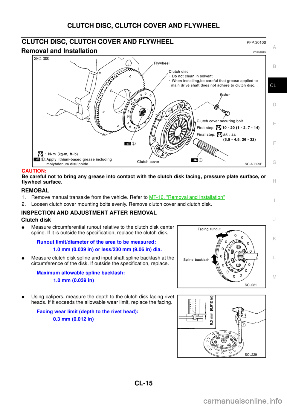
Removal and InstallationECS0 01 W K
CAUTION:
Be careful not to bring any grease into contact with the clutch disk facing, pressure plate surface, or
flywheel surface.
REMOBAL
1. Remove manual transaxle from the vehicle. Refer toMT-16, "Removal and Installation"
2. Loosen clutch cover mounting bolts evenly. Remove clutch cover and clutch disk.
INSPECTION AND ADJUSTMENT AFTER REMOVAL
Clutch disk
lMeasure circumferential runout relative to the clutch disk center
spline. If it is outside the specification, replace the clutch disk.
lMeasure clutch disk spline and input shaft spline backlash at the
circumference of the disk. If outside the specification, replace.
lUsing calipers, measure the depth to the clutch disk facing rivet
heads. If it exceeds the allowable wear limit, replace the facing.
SCIA0329E
Runout limit/diameter of the area to be measured:
1.0 mm (0.039 in) or less/230 mm (9.06 in) dia.
Maximum allowable spline backlash:
1.0 mm (0.039 in)
SCL221
Facing wear limit (depth to the rivet head):
0.3 mm (0.012 in)
SCL229
Page 1008 of 3066
CL-16
CLUTCH DISC, CLUTCH COVER AND FLYWHEEL
Clutch cover
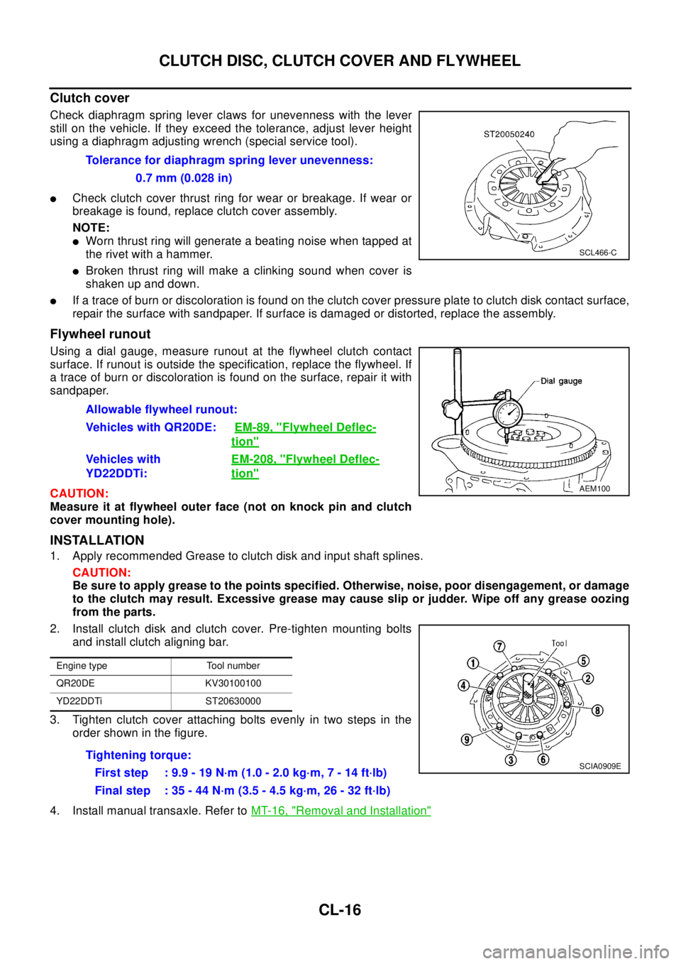
Check diaphragm spring lever claws for unevenness with the lever
still on the vehicle. If they exceed the tolerance, adjust lever height
using a diaphragm adjusting wrench (special service tool).
lCheck clutch cover thrust ring for wear or breakage. If wear or
breakage is found, replace clutch cover assembly.
NOTE:
lWorn thrust ring will generate a beating noise when tapped at
therivetwithahammer.
lBroken thrust ring will make a clinking sound when cover is
shaken up and down.
lIf a trace of burn or discoloration is found on the clutch cover pressure plate to clutch disk contact surface,
repair the surface with sandpaper. If surface is damaged or distorted, replace the assembly.
Flywheel runout
Using a dial gauge, measure runout at the flywheel clutch contact
surface. If runout is outside the specification, replace the flywheel. If
a trace of burn or discoloration is found on the surface, repair it with
sandpaper.
CAUTION:
Measure it at flywheel outer face (not on knock pin and clutch
cover mounting hole).
INSTALLATION
1. Apply recommended Grease to clutch disk and input shaft splines.
CAUTION:
Be sure to apply grease to the points specified. Otherwise, noise, poor disengagement, or damage
to the clutch may result. Excessive grease may cause slip or judder. Wipe off any grease oozing
from the parts.
2. Install clutch disk and clutch cover. Pre-tighten mounting bolts
and install clutch aligning bar.
3. Tighten clutch cover attaching bolts evenly in two steps in the
order shown in the figure.
4. Install manual transaxle. Refer toMT-16, "
Removal and Installation"
Tolerance for diaphragm spring lever unevenness:
0.7 mm (0.028 in)
SCL466-C
Allowable flywheel runout:
Vehicles with QR20DE:EM-89, "
Flywheel Deflec-
tion"
Vehicles with
YD22DDTi:EM-208, "Flywheel Deflec-
tion"
AEM100
Engine type Tool number
QR20DE KV30100100
YD22DDTi ST20630000
Tightening torque:
First step : 9.9 - 19 N·m (1.0 - 2.0 kg·m, 7 - 14 ft·lb)
Final step : 35 - 44 N·m (3.5 - 4.5 kg·m, 26 - 32 ft·lb)SCIA0909E