steering wheel NISSAN X-TRAIL 2003 Electronic Repair Manual
[x] Cancel search | Manufacturer: NISSAN, Model Year: 2003, Model line: X-TRAIL, Model: NISSAN X-TRAIL 2003Pages: 3066, PDF Size: 51.47 MB
Page 2969 of 3066
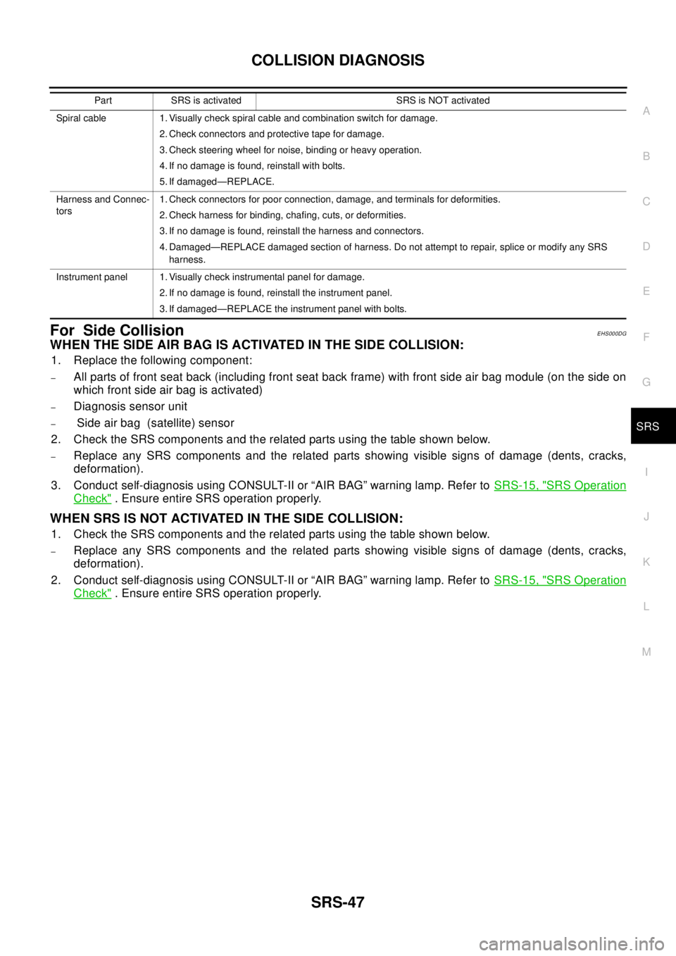
COLLISION DIAGNOSIS
SRS-47
C
D
E
F
G
I
J
K
L
MA
B
SRS
For Side CollisionEHS000DG
WHENTHESIDEAIRBAGISACTIVATEDINTHESIDECOLLISION:
1. Replace the following component:
–All parts of front seat back (including front seat back frame) with front side air bag module (on the side on
which front side air bag is activated)
–Diagnosis sensor unit
–Side air bag (satellite) sensor
2. Check the SRS components and the related parts using the table shown below.
–Replace any SRS components and the related parts showing visible signs of damage (dents, cracks,
deformation).
3. Conduct self-diagnosis using CONSULT-II or “AIR BAG” warning lamp. Refer toSRS-15, "
SRS Operation
Check". Ensure entire SRS operation properly.
WHEN SRS IS NOT ACTIVATED IN THE SIDE COLLISION:
1. Check the SRS components and the related parts using the table shown below.
–Replace any SRS components and the related parts showing visible signs of damage (dents, cracks,
deformation).
2. Conduct self-diagnosis using CONSULT-II or “AIR BAG” warning lamp. Refer toSRS-15, "
SRS Operation
Check". Ensure entire SRS operation properly.
Spiral cable 1. Visually check spiral cable and combination switch for damage.
2. Check connectors and protective tape for damage.
3. Check steering wheel for noise, binding or heavy operation.
4. If no damage is found, reinstall with bolts.
5. If damaged—REPLACE.
Harness and Connec-
tors1. Check connectors for poor connection, damage, and terminals for deformities.
2. Check harness for binding, chafing, cuts, or deformities.
3. If no damage is found, reinstall the harness and connectors.
4. Damaged—REPLACE damaged section of harness. Do not attempt to repair, splice or modify any SRS
harness.
Instrument panel 1. Visually check instrumental panel for damage.
2. If no damage is found, reinstall the instrument panel.
3. If damaged—REPLACE the instrument panel with bolts. Part SRS is activated SRS is NOT activated
Page 2972 of 3066

TF-2
SEVERAL SECONDS AFTER ENGINE
STARTED.(4WD MODE INDICATOR LAMP
GOES OUT) ........................................................ 55
HEAVY TIGHT-CORNER BRAKING SYMPTOM
OCCURS WHEN THE VEHICLE IS DRIVEN IN
AUTO MODE AND THE STEERING WHEEL IS
TURNED FULLY TO EITHER SIDE AFTER THE
ENGINE IS STARTED ......................................... 56
4WD MODES CANNOT BE SWITCHED AFTER
ENGINE IS STARTED ......................................... 57
WHILE DRIVING, 4WD WARNING LAMP
FLASHES RAPIDLY.(WHEN IT FLASHERSFOR
APPROX. ONE MINUTE, THEN DOES NOT
ILLUMINATE.) ..................................................... 57
WHILE DRIVING, 4WD WARNING LAMP
FLASHES SLOWLY. (WHEN IT CONTINUES TO
ILLUMINATE UNTIL ENGINE TURNS OFF.) ...... 58
VEHICLE DOES NOT ENTER 4WD MODEEVEN THOUGH 4WD WARNING LAMP IS OFF.... 58
TIGHT-CONER BRAKING SYMPTOM OCCURS
WHEN THE VEHICLE IS STARTED IN AUTO
WARNING LAMP REMAIN OFF). .......................58
4WD ACTUATOR RELAY (4WD SOLENOID
ACTUATOR RELAY) TURNS ON/OFF FRE-
QUENTLY ............................................................58
SERVICE DATA AND SPECIFICATIONS (SDS) ......60
General Specifications ............................................60
Inspection and Adjustment ......................................60
PRELOAD TORQUE BEFORE DISASSEMBLY...60
PRELOAD TORQUE AFTER DISASSEMBLY
AND REASSEMBLY ............................................60
BACKLSH ............................................................60
SELECTIVE PARTS ............................................60
PINION SLEEVE SHIM ........................................61
Page 3004 of 3066

TF-34
ALL MODE 4X4 SYSTEM
INPUT/OUTPUT SIGNAL
T: Transmit R: Receive
Signals ECMSteering wheel
angle sensor4WD control unitESP/ TCS / ABS
control unit
Engine speed signal T R R
Accelerator pedal position signal T R
ESP operation signal R R T
TCS operation signal R R T
ABS operation signal R R T
Stop lamp switch signalRT
Steering wheel angle sensor signal T R
ESP-OFFSW signalRT
Wheel speed sensor signalRT
4WD Mode signalTR
Page 3011 of 3066
TROUBLE DIAGNOSIS
TF-41
C
E
F
G
H
I
J
K
L
MA
B
TF
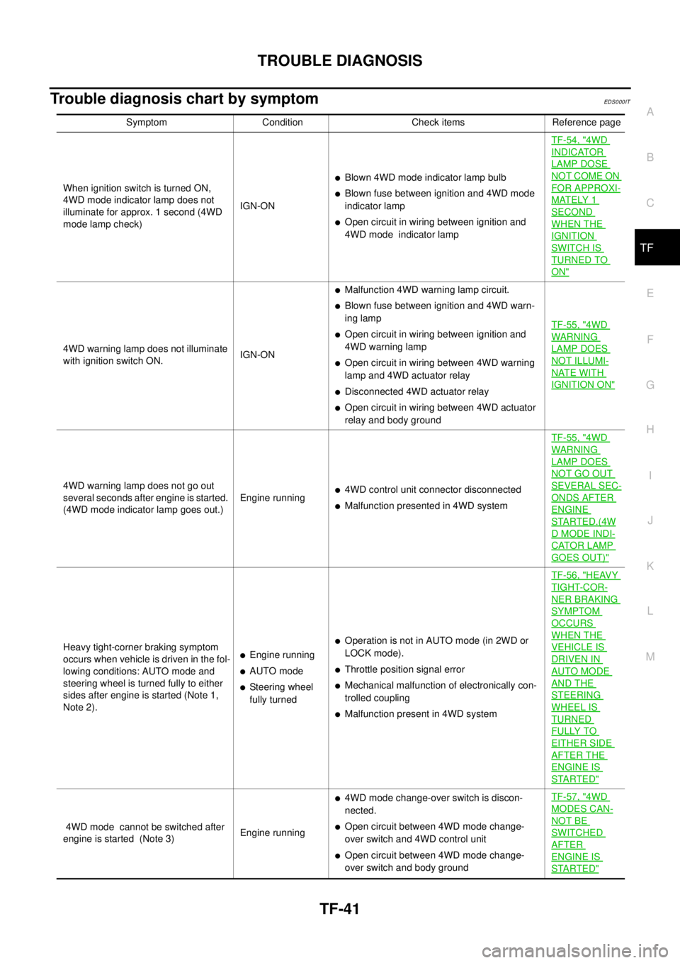
Trouble diagnosis chart by symptomEDS0 00 IT
Symptom Condition Check items Reference page
When ignition switch is turned ON,
4WD mode indicator lamp does not
illuminate for approx. 1 second (4WD
mode lamp check)IGN-ON
lBlown 4WD mode indicator lamp bulb
lBlown fuse between ignition and 4WD mode
indicator lamp
lOpen circuit in wiring between ignition and
4WD mode indicator lampTF-54, "
4WD
INDICATOR
LAMP DOSE
NOT COME ON
FOR APPROXI-
MATELY 1
SECOND
WHEN THE
IGNITION
SWITCH IS
TURNED TO
ON"
4WD warning lamp does not illuminate
with ignition switch ON.IGN-ON
lMalfunction 4WD warning lamp circuit.
lBlown fuse between ignition and 4WD warn-
ing lamp
lOpen circuit in wiring between ignition and
4WD warning lamp
lOpen circuit in wiring between 4WD warning
lamp and 4WD actuator relay
lDisconnected 4WD actuator relay
lOpen circuit in wiring between 4WD actuator
relay and body groundTF-55, "
4WD
WAR NIN G
LAMP DOES
NOT ILLUMI-
NATE WITH
IGNITION ON"
4WD warning lamp does not go out
several seconds after engine is started.
(4WD mode indicator lamp goes out.)Engine runningl4WD control unit connector disconnected
lMalfunction presented in 4WD systemTF-55, "
4WD
WAR NIN G
LAMP DOES
NOT GO OUT
SEVERAL SEC-
ONDS AFTER
ENGINE
STARTED.(4W
DMODEINDI-
CATOR LAMP
GOES OUT)"
Heavy tight-corner braking symptom
occurs when vehicle is driven in the fol-
lowing conditions: AUTO mode and
steering wheel is turned fully to either
sides after engine is started (Note 1,
Note 2).lEngine running
lAUTO mode
lSteering wheel
fully turned
lOperation is not in AUTO mode (in 2WD or
LOCK mode).
lThrottle position signal error
lMechanical malfunction of electronically con-
trolled coupling
lMalfunction present in 4WD systemTF-56, "
HEAVY
TIGHT-COR-
NER BRAKING
SYMPTOM
OCCURS
WHEN THE
VEHICLE IS
DRIVEN IN
AUTO MODE
AND THE
STEERING
WHEEL IS
TURNED
FULLY TO
EITHER SIDE
AFTER THE
ENGINE IS
STARTED"
4WD mode cannot be switched after
engine is started (Note 3)Engine running
l4WD mode change-over switch is discon-
nected.
lOpen circuit between 4WD mode change-
over switch and 4WD control unit
lOpen circuit between 4WD mode change-
over switch and body groundTF-57, "
4WD
MODES CAN-
NOT BE
SWITCHED
AFTER
ENGINE IS
STARTED"
Page 3012 of 3066
TF-42
TROUBLE DIAGNOSIS
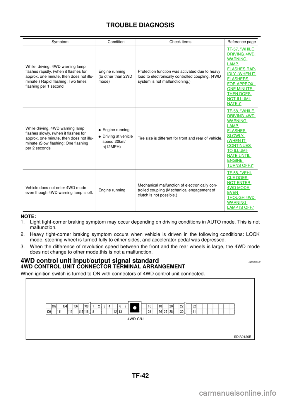
NOTE:
1. Light tight-corner braking symptom may occur depending on driving conditions in AUTO mode. This is not
malfunction.
2. Heavy tight-corner braking symptom occurs when vehicle is driven in the following conditions: LOCK
mode, steering wheel is turned fully to either sides, and accelerator pedal was depressed.
3. When the difference of revolution speed between the front and the rear wheels is large, the 4WD mode
does not change to other mode.this is not a malfunction.
4WD control unit input/output signal standardEDS000H9
4WD CONTROL UNIT CONNECTOR TERMINAL ARRANGEMENT
When ignition switch is turned to ON with connectors of 4WD control unit connected.
While driving, 4WD warning lamp
flashes rapidly. (when it flashes for
approx. one minute, then does not illu-
minate.) Rapid flashing: Two times
flashing per 1 secondEngine running
(to other than 2WD
mode)Protection function was activated due to heavy
load to electronically controlled coupling. (4WD
system is not malfunctioning.)TF-57, "
WHILE
DRIVING, 4WD
WARN ING
LAMP
FLASHES RAP-
IDLY. (WHEN IT
FLASHERS
FOR APPROX.
ONE MINUTE,
THEN DOES
NOT ILLUMI-
NATE.)"
While driving, 4WD warning lamp
flashes slowly. (when it flashes for
approx. one minute, then does not illu-
minate.)Slow flashing: One flashing
per 2 secondslEngine running
lDriving at vehicle
speed 20km/
h(12MPH)Tire size is different for front and rear of vehicle.TF-58, "
WHILE
DRIVING, 4WD
WARN ING
LAMP
FLASHES
SLOWLY.
(WHEN IT
CONTINUES
TO ILLUMI-
NATE UNTIL
ENGINE
TURNS OFF.)"
Vehicle does not enter 4WD mode
even though 4WD warning lamp is off.Engine runningMechanical malfunction of electronically con-
trolled coupling (Mechanical engagement of
clutch is not possible.)TF-58, "
VEHI-
CLE DOES
NOT ENTER
4WD MODE
EVEN
THOUGH 4WD
WARN ING
LAMP IS OFF."
Symptom Condition Check items Reference page
SDIA0120E
Page 3026 of 3066

TF-56
TROUBLE DIAGNOSIS
2.4WD CONTROL UNIT CONNECTOR CONNECTION INSPECTION
lCheck 4WD control unit connector for proper connection.
OK or NG
OK >> Reconnect the 4WD control unit connector properly and perform inspection again.
NG >> Repair or replace the connector.
HEAVY TIGHT-CORNER BRAKING SYMPTOM OCCURS WHEN THE VEHICLE IS DRIVEN IN
AUTO MODE AND THE STEERING WHEEL IS TURNED FULLY TO EITHER SIDE AFTER THE
ENGINE IS STARTED
1.PERFORM SELF-DIAGNOSIS.
Using CONSULT-II perform self-diagnosis.
OK or NG
OK >> GO TO 2. (No self-diagnosis malfunction indicated.)
NG >> Determine the location of the malfunction according to the result of self-diagnosis using CON-
SULT-II. (Malfunction is present in the 4WD system.)
2.CHECK USING THE DATA MONITOR FUNCTION OF THE CONSULT- II.
lPerform inspection by the data monitor function of the CONSULT-II.
lCheck that the operation is in AUTO mode.
lMeasure voltage when the accelerator pedal is not depressed. (Accelerator pedal not depressed: approx.
0.5V or lower)
lMeasure the current supplied to the 4WD solenoid valve. (Accelerator pedal not depressed: approx. 0A)
OK or NG
OK >> GO TO 3. (No self-diagnosis malfunction indicated.)
NG >>
lNot in AUTO mode. GO TO 3.
lVoltage when accelerator pedal is not depressed is higher than approximately 0.5V.
l4WD solenoid valve current when the accelerator pedal is not depressed is other than 0A.
lCountermeasure: Keep the vehicle idling for approximately 15 minutes before checking again.
(Voltage when accelerator pedal is not depressed will be automatically reset to zero during this
period.)
Page 3034 of 3066

WT-2
NOISE, VIBRATION, AND HARSHNESS (NVH) TROUBLESHOOTING
NOISE, VIBRATION, AND HARSHNESS (NVH) TROUBLESHOOTING
PFP:00003
NVH Troubleshooting ChartEES000J1
Use the chart below to help you find the cause of the symptom. If necessary, repair or replace these parts.
´: ApplicableReference page
Refer toWT-3
—
—
—
—
—
—
NVHinPRsection.
NVH in RFD section.
NVHinFAXandFSUsections.
NVH in RAX and RSU sections.
Refer to TIRES in this chart.
Refer to ROAD WHEEL in this chart.
NVH in RAX section.
NVHinBRsection.
NVH in PS section.
Possible cause and SUSPECTED PARTS
Out-of-round
Imbalance
Incorrect tire pressure
Uneven tire wear
Deformation or damage
Non-uniformity
Incorrect tire size
PROPELLER SHAFT
DIFFERETIAL
FRONT AXLE AND FRONT SUSPENSION
REAR AXLE AND REAR SUSPENSION
TIRES
ROAD WHEEL
DRIVE SHAFT
BRAKE
STEERING
SymptomTIRESNoise´´´´´´ ´´´´ ´´´´
Shake´´´´´ ´´ ´´ ´´´´
Vibration´´´´´´´
Shimmy´´´´´´´ ´´ ´ ´´
Judder´´´´´ ´ ´´ ´ ´´
Poor quality ride
or handling´´´´´ ´ ´´ ´
ROAD WHEELNoise´´ ´ ´´´´´ ´´´
Shake´´ ´ ´ ´´´ ´´´
Shimmy, Judder´´ ´ ´´´ ´´
Poor quality ride
or handling´´ ´ ´´´