check oil NISSAN X-TRAIL 2003 Electronic Repair Manual
[x] Cancel search | Manufacturer: NISSAN, Model Year: 2003, Model line: X-TRAIL, Model: NISSAN X-TRAIL 2003Pages: 3066, PDF Size: 51.47 MB
Page 2528 of 3066
MA-36
CHASSIS AND BODY MAINTENANCE
2. Check oil level.
CAUTION:
Do not reuse gasket.
Checking A/T FluidELS000BV
1. Warm up engine.
2. Check for fluid leakage.
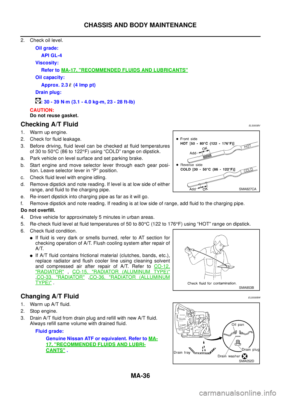
3. Before driving, fluid level can be checked at fluid temperatures
of 30 to 50°C (86 to 122°F) using “COLD” range on dipstick.
a. Park vehicle on level surface and set parking brake.
b. Start engine and move selector lever through each gear posi-
tion. Leave selector lever in “P” position.
c. Check fluid level with engine idling.
d. Remove dipstick and note reading. If level is at low side of either
range, and fluid to the charging pipe.
e. Re-insert dipstick into charging pipe as far as it will go.
f. Remove dipstick and note reading. If reading is at low side of range, add fluid to the charging pipe.
Do not overfill.
4. Drive vehicle for approximately 5 minutes in urban areas.
5. Re-check fluid level at fluid temperatures of 50 to 80°C (122 to 176°F) using “HOT” range on dipstick.
6. Check fluid condition.
lIf fluid is very dark or smells burned, refer to AT section for
checking operation of A/T. Flush cooling system after repair of
A/T.
lIf A/T fluid contains frictional material (clutches, bands, etc.),
replace radiator and flush cooler line using cleaning solvent
and compressed air after repair of A/T. Refer toCO-12,
"RADIATOR",CO-15, "RADIATOR (ALUMINUM TYPE)"
,CO-33, "RADIATOR",CO-36, "RADIATOR (ALLUMINUM
TYPE)".
Changing A/T FluidELS000BW
1. Warm up A/T fluid.
2. Stop engine.
3. Drain A/T fluid from drain plug and refill with new A/T fluid.
Always refill same volume with drained fluid.Oil grade:
API GL-4
Viscosity:
Refer toMA-17, "
RECOMMENDED FLUIDS AND LUBRICANTS"
Oil capacity:
Approx. 2.3 (4 lmp pt)
Drain plug:
: 30 - 39 N·m (3.1 - 4.0 kg-m, 23 - 28 ft-lb)
SMA827CA
SMA853B
Fluid grade:
Genuine Nissan ATF or equivalent. Refer toMA-
17, "RECOMMENDED FLUIDS AND LUBRI-
CANTS".
SMA052D
Page 2529 of 3066
CHASSIS AND BODY MAINTENANCE
MA-37
C
D
E
F
G
H
I
J
K
MA
B
MA
4. Run engine at idle speed for five minutes.
5. Check fluid level and condition. Refer to “Checking A/T Fluid”. If fluid is still dirty, repeat steps 2 through 5.
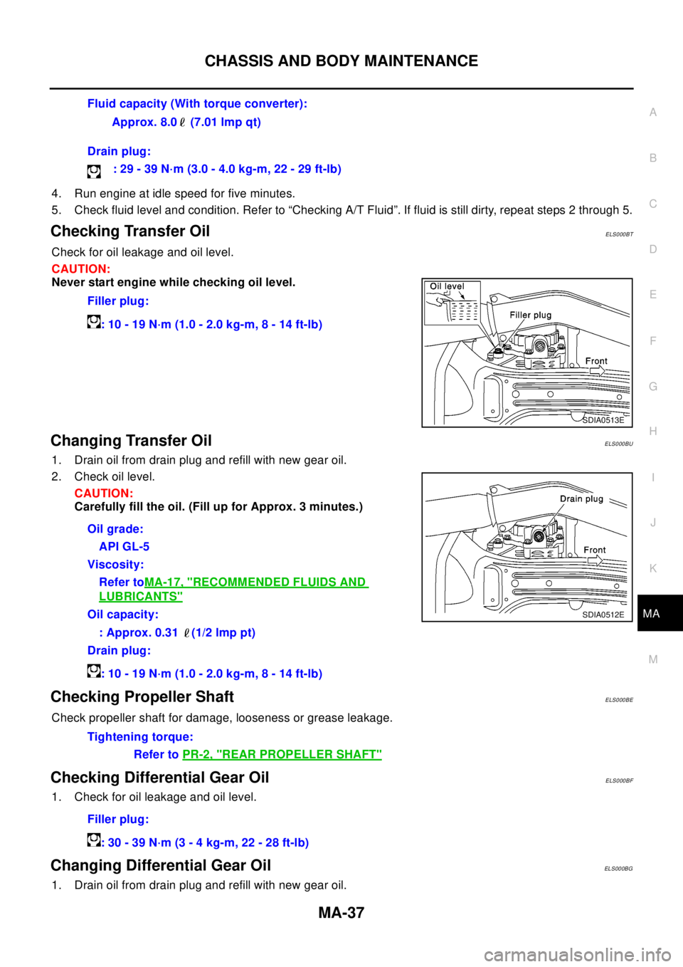
Checking Transfer OilELS000BT
Check for oil leakage and oil level.
CAUTION:
Never start engine while checking oil level.
Changing Transfer OilELS000BU
1. Drain oil from drain plug and refill with new gear oil.
2. Check oil level.
CAUTION:
Carefully fill the oil. (Fill up for Approx. 3 minutes.)
Checking Propeller ShaftELS000BE
Check propeller shaft for damage, looseness or grease leakage.
Checking Differential Gear OilELS000BF
1. Check for oil leakage and oil level.
Changing Differential Gear OilELS000BG
1. Drain oil from drain plug and refill with new gear oil.Fluid capacity (With torque converter):
Approx. 8.0 (7.01 lmp qt)
Drain plug:
:29-39N·m(3.0-4.0kg-m,22-29ft-lb)
Filler plug:
:10-19N·m(1.0-2.0kg-m,8-14ft-lb)
SDIA0513E
Oil grade:
API GL-5
Viscosity:
Refer toMA-17, "
RECOMMENDED FLUIDS AND
LUBRICANTS"
Oil capacity:
: Approx. 0.31 (1/2 lmp pt)
Drain plug:
:10-19N·m(1.0-2.0kg-m,8-14ft-lb)SDIA0512E
Tightening torque:
Refer toPR-2, "
REAR PROPELLER SHAFT"
Filler plug:
:30-39N·m(3-4kg-m,22-28ft-lb)
Page 2530 of 3066
MA-38
CHASSIS AND BODY MAINTENANCE
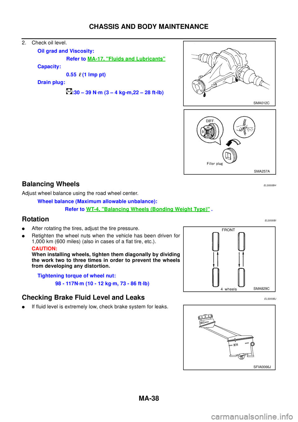
2. Check oil level.
Balancing WheelsELS000BH
Adjust wheel balance using the road wheel center.
RotationELS000BI
lAfter rotating the tires, adjust the tire pressure.
lRetighten the wheel nuts when the vehicle has been driven for
1,000 km (600 miles) (also in cases of a flat tire, etc.).
CAUTION:
When installing wheels, tighten them diagonally by dividing
the work two to three times in order to prevent the wheels
from developing any distortion.
Checking Brake Fluid Level and LeaksELS000BJ
lIf fluid level is extremely low, check brake system for leaks.Oil grad and Viscosity:
Refer toMA-17, "
Fluids and Lubricants"
Capacity:
0.55 (1 lmp pt)
Drain plug:
:30–39N·m(3–4kg-m,22–28ft-lb)
SMA012C
SMA257A
Wheel balance (Maximum allowable unbalance):
Refer toWT-4, "
Balancing Wheels (Bonding Weight Type)".
Tightening torque of wheel nut:
98 - 117N·m (10 - 12 kg·m, 73 - 86 ft·lb)
SMA829C
SFIA0066J
Page 2533 of 3066
CHASSIS AND BODY MAINTENANCE
MA-41
C
D
E
F
G
H
I
J
K
MA
B
MA
Checking Power Steering Fluid and LinesELS000BP
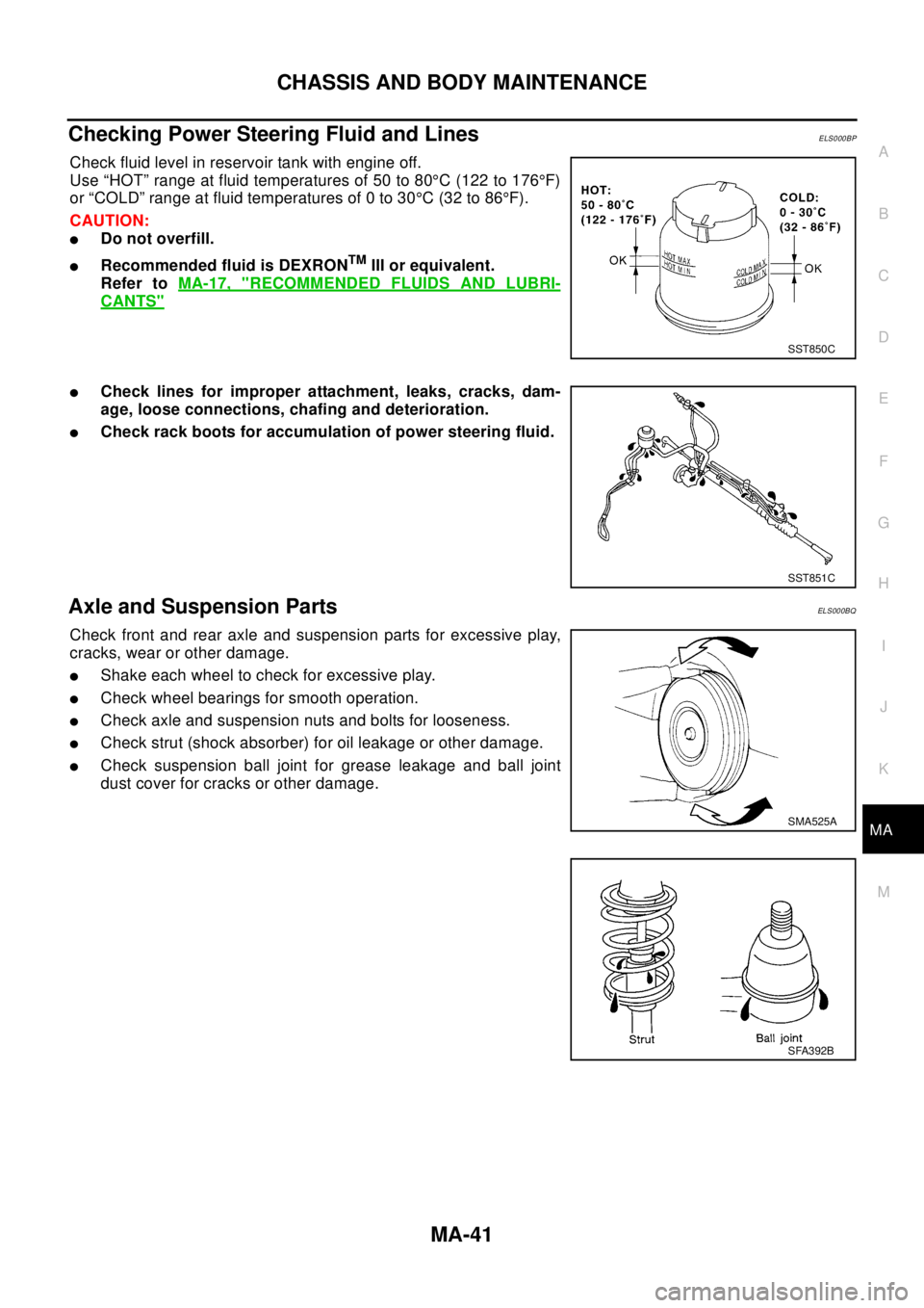
Check fluid level in reservoir tank with engine off.
Use “HOT” range at fluid temperatures of 50 to 80°C (122 to 176°F)
or “COLD” range at fluid temperatures of 0 to 30°C(32to86°F).
CAUTION:
lDo not overfill.
lRecommended fluid is DEXRONTMIII or equivalent.
Refer toMA-17, "
RECOMMENDED FLUIDS AND LUBRI-
CANTS"
lCheck lines for improper attachment, leaks, cracks, dam-
age, loose connections, chafing and deterioration.
lCheck rack boots for accumulation of power steering fluid.
Axle and Suspension PartsELS000BQ
Check front and rear axle and suspension parts for excessive play,
cracks, wear or other damage.
lShake each wheel to check for excessive play.
lCheck wheel bearings for smooth operation.
lCheck axle and suspension nuts and bolts for looseness.
lCheck strut (shock absorber) for oil leakage or other damage.
lCheck suspension ball joint for grease leakage and ball joint
dust cover for cracks or other damage.
SST850C
SST851C
SMA525A
SFA392B
Page 2537 of 3066
MT-1
MANUAL TRANSAXLE
C TRANSMISSION/TRANSAXLE
CONTENTS
D
E
F
G
H
I
J
K
L
M
SECTION
A
B
MT
MANUAL TRANSAXLE
PRECAUTIONS .......................................................... 3
Caution ..................................................................... 3
PREPARATION ........................................................... 4
Special Service Tools ............................................... 4
Commercial Service Tools ........................................ 6
NOISE, VIBRATION, AND HARSHNESS (NVH)
TROUBLESHOOTING ................................................ 8
NVH Troubleshooting Chart ..................................... 8
MANUAL TRANSAXLE ......................................... 8
DESCRIPTION ............................................................ 9
Cross-sectional View ................................................ 9
DOUBLE-CONE SYNCHRONIZER .................... 10
REVERSE GEAR NOISE PREVENTION FUNC-
TION (SYNCHRONIZING METHOD) ................. 10
M/T OIL ......................................................................11
Changing M/T Oil ....................................................11
DRAINING ............................................................11
FILLING ................................................................11
Checking M/T Oil .....................................................11
OIL LEAKAGE AND OIL LEVEL ..........................11
SIDE OIL SEAL ........................................................ 12
Removal and Installation ........................................ 12
REMOVAL ........................................................... 12
INSTALLATION ................................................... 12
POSITION SWITCH .................................................. 13
Checking ................................................................ 13
BACK-UP LAMP SWITCH .................................. 13
PARK/NEUTRAL POSITION SWITCH ............... 13
CONTROL LINKAGE ............................................... 14
Removal and Installation of Control Device and
Cable ...................................................................... 14
AIR BREATHER HOSE ............................................ 15
Removal and Installation ........................................ 15
TRANSAXLE ASSEMBLY ........................................ 16
Removal and Installation ........................................ 16
REMOVAL ........................................................... 16
INSTALLATION ................................................... 17
Component Parts (RS5F51A) ................................ 18CASE AND HOUSING COMPONENTS .............. 18
GEAR COMPONENTS ....................................... 19
SHIFT CONTROL COMPONENTS ..................... 21
FINAL DRIVE COMPONENTS ........................... 22
Component Parts (RS6F51A) ................................. 23
CASE AND HOUSING COMPONENTS .............. 23
GEAR COMPONENTS ....................................... 24
SHIFT CONTROL COMPONENTS ..................... 26
FINAL DRIVE COMPONENTS ........................... 27
Disassembly and Assembly (RS5F51A) ................. 27
DISASSEMBLY ................................................... 27
ASSEMBLY ......................................................... 30
Disassembly and Assembly (RS6F51A) ................. 35
DISASSEMBLY ................................................... 35
ASSEMBLY ......................................................... 39
Adjustment (RS5F51A) ........................................... 44
INPUTSHAFT END PLAY ................................... 44
DIFFERENTIAL SIDE BEARING PRELOAD ...... 45
MAINSHAFT END PLAY ..................................... 46
REVERSE IDLER GEAR END PLAY .................. 47
Adjustment (RS6F51A) ........................................... 48
INPUTSHAFT END PLAY ................................... 48
DIFFERENTIAL SIDE BEARING PRELOAD ...... 49
MAINSHAFT END PLAY ..................................... 51
REVERSE IDLER GEAR END PLAY .................. 52
INPUT SHAFT AND GEARS .................................... 53
Assembly and Disassembly (RS5F51A) ................. 53
DISASSEMBLY ................................................... 53
INSPECTION AFTER DISASSEMBLY ................ 54
ASSEMBLY ......................................................... 55
Assembly and Disassembly (RS6F51A) ................. 60
DISASSEMBLY ................................................... 60
INSPECTION AFTER DISASSEMBLY ................ 61
ASSEMBLY ......................................................... 62
MAINSHAFT AND GEARS ....................................... 67
Assembly and Disassembly (RS5F51A) ................. 67
DISASSEMBLY ................................................... 67
INSPECTION AFTER DISASSEMBLY ................ 68
Page 2539 of 3066

PRECAUTIONS
MT-3
D
E
F
G
H
I
J
K
L
MA
B
MT
PRECAUTIONSPFP:00001
CautionECS001WO
lDo not reuse transaxle oil, once it has been drained.
lCheck oil level or replace oil with vehicle on level ground.
lDuring removal or installation, keep inside of transaxle clear of dust or dirt.
lCheck for the correct installation status prior to removal or disassembly. If mating marks are required, be
certain they do not interfere with the function of the parts they are applied to.
lIn principle, tighten bolts or nuts gradually in several steps working diagonally from inside to outside. If
tightening sequence is specified, observe it.
lBe careful not to damage sliding surfaces and mating surfaces.
Page 2544 of 3066
MT-8
NOISE, VIBRATION, AND HARSHNESS (NVH) TROUBLESHOOTING
NOISE, VIBRATION, AND HARSHNESS (NVH) TROUBLESHOOTING
PFP:00003
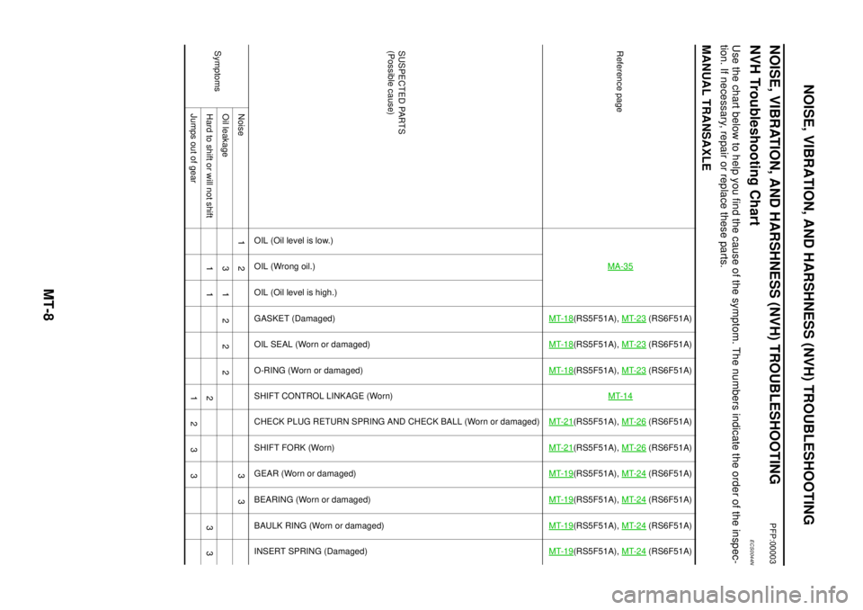
NVH Troubleshooting ChartECS0044N
Use the chart below to help you find the cause of the symptom. The numbers indicate the order of the inspec-
tion. If necessary, repair or replace these parts.
MANUAL TRANSAXLE
Reference pageMA-35
MT-18
(RS5F51A),MT-23
(RS6F51A)
MT-18
(RS5F51A),MT-23
(RS6F51A)
MT-18
(RS5F51A),MT-23
(RS6F51A)
MT-14
MT-21
(RS5F51A),MT-26
(RS6F51A)
MT-21
(RS5F51A),MT-26
(RS6F51A)
MT-19
(RS5F51A),MT-24
(RS6F51A)
MT-19
(RS5F51A),MT-24
(RS6F51A)
MT-19
(RS5F51A),MT-24
(RS6F51A)
MT-19
(RS5F51A),MT-24
(RS6F51A)
SUSPECTED PARTS
(Possible cause)
OIL (Oil level is low.)
OIL(Wrongoil.)
OIL (Oil level is high.)
GASKET (Damaged)
OIL SEAL (Worn or damaged)
O-RING (Worn or damaged)
SHIFT CONTROL LINKAGE (Worn)
CHECK PLUG RETURN SPRING AND CHECK BALL (Worn or damaged)
SHIFT FORK (Worn)
GEAR (Worn or damaged)
BEARING (Worn or damaged)
BAULK RING (Worn or damaged)
INSERT SPRING (Damaged)
SymptomsNoise 1 2 3 3
Oilleakage 31222
Hard to shift or will not shift 1 1 2 3 3
Jumps out of gear 1 2 3 3
Page 2547 of 3066
M/T OIL
MT-11
D
E
F
G
H
I
J
K
L
MA
B
MT
M/T OILPFP:KLD20
Changing M/T OilECS001WQ
DRAINING
1. Start the engine and let it run to warm up the transaxle.
2. Stop the engine. Remove drain plug and drain oil.
3. Set a gasket on the drain plug and install it to the transaxle.
CAUTION:
Do not reuse gasket.
FILLING
1. Remove filler plug. Fill with new oil until oil level reaches the specified limit near filler plug mounting hole.
2. After refilling oil, check oil level. Assemble gasket to filler plug, then install it to transaxle body.
CAUTION:
Do not reuse gasket.
Checking M/T OilECS001WR
OIL LEAKAGE AND OIL LEVEL
lCheck that oil is not leaking from transaxle or around it.
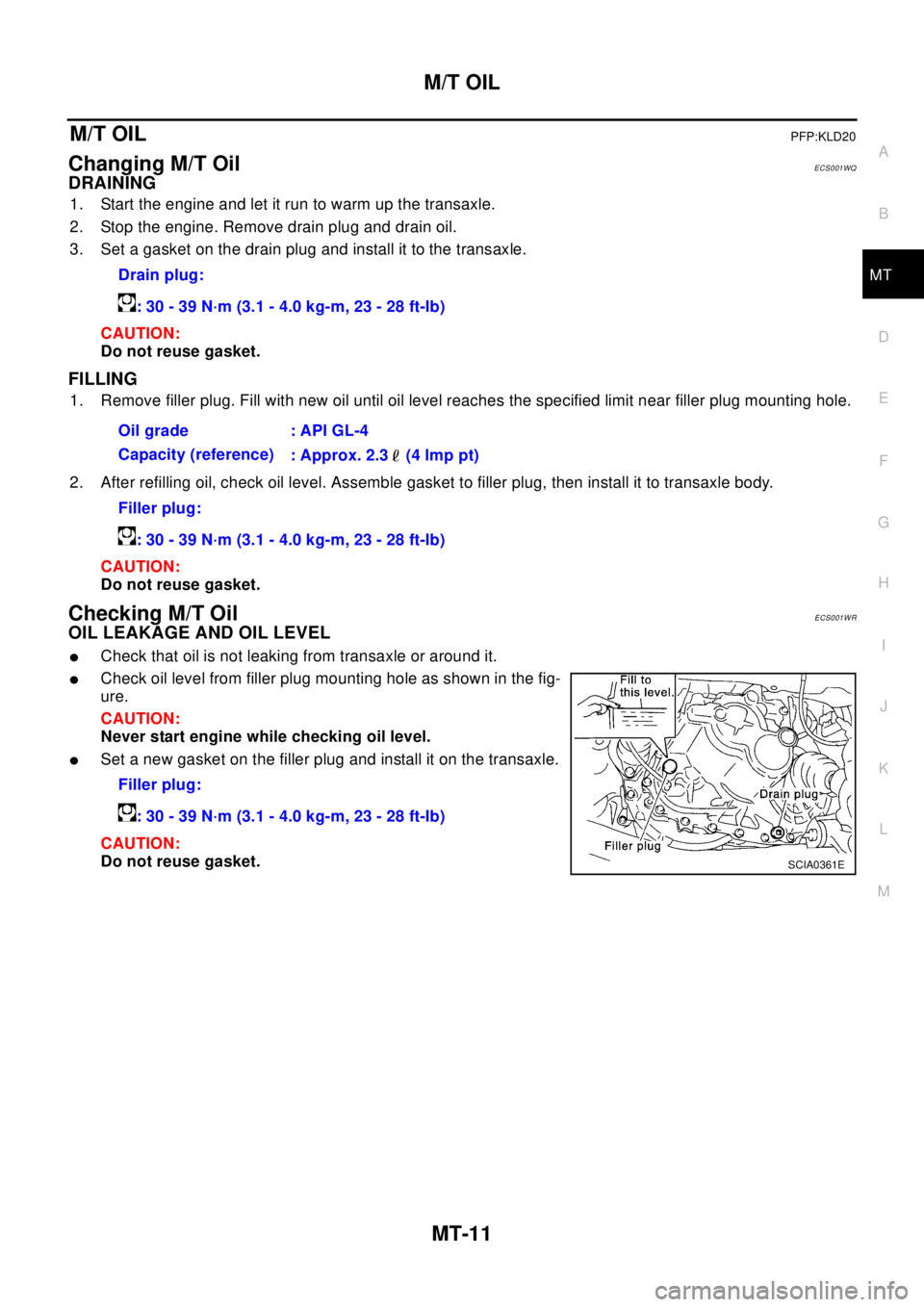
lCheck oil level from filler plug mounting hole as shown in the fig-
ure.
CAUTION:
Never start engine while checking oil level.
lSet a new gasket on the filler plug and install it on the transaxle.
CAUTION:
Do not reuse gasket.Drain plug:
: 30 - 39 N·m (3.1 - 4.0 kg-m, 23 - 28 ft-lb)
Oil grade : API GL-4
Capacity (reference)
: Approx. 2.3 (4 lmp pt)
Filler plug:
: 30 - 39 N·m (3.1 - 4.0 kg-m, 23 - 28 ft-lb)
Filler plug:
: 30 - 39 N·m (3.1 - 4.0 kg-m, 23 - 28 ft-lb)
SCIA0361E
Page 2548 of 3066
MT-12
SIDE OIL SEAL
SIDE OIL SEAL
PFP:32113
Removal and InstallationECS001WS
REMOVAL
lClutch housing side oil seal used on 4WD vehicles is attached to the transfer. Be sure to replace it
when transfer is removed.
1. Remove the driveshaft from the transaxle.
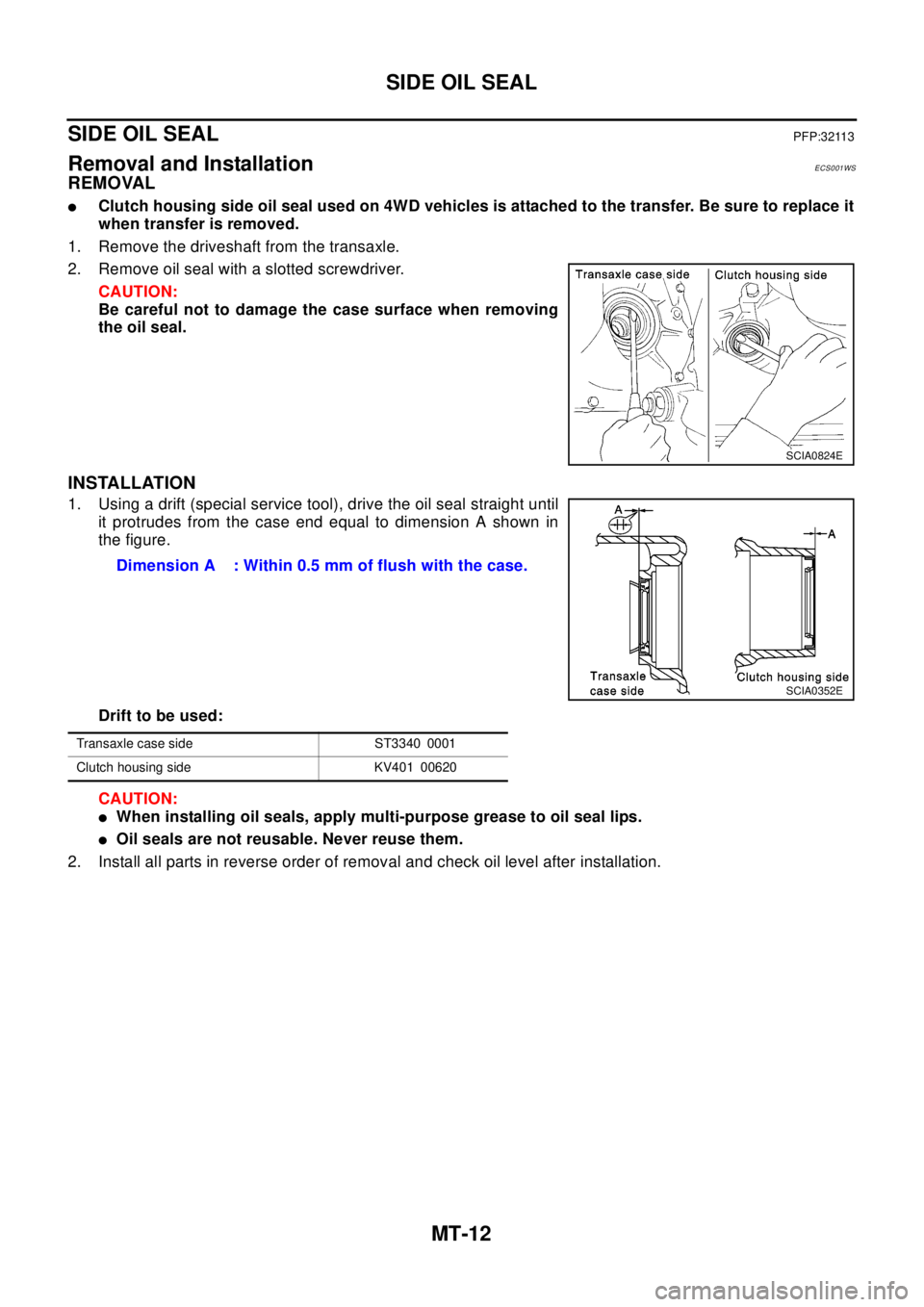
2. Remove oil seal with a slotted screwdriver.
CAUTION:
Be careful not to damage the case surface when removing
the oil seal.
INSTALLATION
1. Using a drift (special service tool), drive the oil seal straight until
it protrudes from the case end equal to dimension A shown in
the figure.
Drift to be used:
CAUTION:
lWhen installing oil seals, apply multi-purpose grease to oil seal lips.
lOil seals are not reusable. Never reuse them.
2. Install all parts in reverse order of removal and check oil level after installation.
SCIA0824E
Dimension A : Within 0.5 mm of flush with the case.
SCIA0352E
Transaxle case side ST3340 0001
Clutch housing side KV401 00620
Page 2553 of 3066
TRANSAXLE ASSEMBLY
MT-17
D
E
F
G
H
I
J
K
L
MA
B
MT
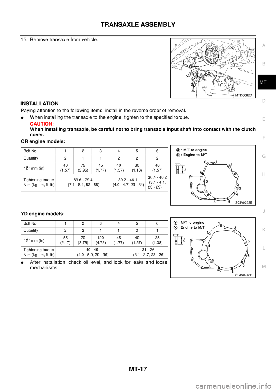
15. Remove transaxle from vehicle.
INSTALLATION
Paying attention to the following items, install in the reverse order of removal.
lWhen installing the transaxle to the engine, tighten to the specified torque.
CAUTION:
When installing transaxle, be careful not to bring transaxle input shaft into contact with the clutch
cover.
QR engine models:
YD engine models:
lAfter installation, check oil level, and look for leaks and loose
mechanisms.
MTD0062D
Bolt No. 1 2 3 4 5 6
Quantity 2 1 1 2 2 2
“”mm(in)40
(1.57)75
(2.95)45
(1.77)40
(1.57)30
(1.18)40
(1.57)
Tightening torque
N·m (kg - m, ft- lb)69.6 - 79.4
(7.1 - 8.1, 52 - 58)39.2 - 46.1
(4.0 - 4.7, 29 - 34)30.4 - 40.2
(3.1 - 4.1,
23 - 29)
SCIA0353E
Bolt No. 1 2 3 4 5 6
Quantity 2 2 1 1 3 1
“”mm(in)55
(2.17)70
(2.76)120
(4.72)45
(1.77)40
(1.57)35
(1.38)
Tightening torque
N·m (kg - m, ft- lb)40 - 49
(4.0 - 5.0, 29 - 36)31 - 36
(3.1 - 3.7, 23 - 26)
SCIA0748E