check oil NISSAN X-TRAIL 2003 Electronic Repair Manual
[x] Cancel search | Manufacturer: NISSAN, Model Year: 2003, Model line: X-TRAIL, Model: NISSAN X-TRAIL 2003Pages: 3066, PDF Size: 51.47 MB
Page 2766 of 3066
PS-6
STEERING WHEEL
STEERING WHEEL
PFP:48430
On-Vehicle Inspection and ServiceEGS0004E
PLAY INSPECTION
1. Turn steering wheel to straight-ahead position. Start engine and lightly turn steering wheel clockwise and
counter clockwise until front wheels start moving. Measure travel to starting point on circumference of
steering wheel.
2. If play is outside specifications, check following parts for proper installation: steering gear assembly, front
suspension, axles, and steering column
lCheck steering wheel for vertical, horizontal, or axial play.
lLift vehicle and check steering gear mounting bolts and nuts for looseness.
NEUTRAL POSITION INSPECTION
lAfter the wheel alignment inspection, carry out the neutral position inspection. Refer toWT-4.
lBefore removing steering wheel, check steering gear neutral position.
1. Set vehicle to straight-ahead position, and check that steering wheel is in neutral position.
2. If it is not in neutral position, remove steering wheel, and install again in properly.
3. If it is not adjusted within two teeth from center of gear, loosen tie rod lock nut. Then turn it to opposite
direction to adjust until amount of left and right becomes equal.
STEERING TORQUE CHECK
1. Stop vehicle on a dry flat paved road and apply parking brake.
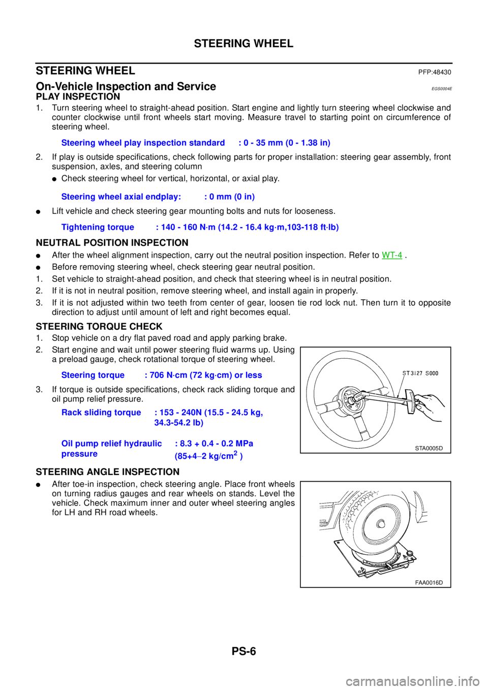
2. Start engine and wait until power steering fluid warms up. Using
a preload gauge, check rotational torque of steering wheel.
3. If torque is outside specifications, check rack sliding torque and
oil pump relief pressure.
STEERING ANGLE INSPECTION
lAfter toe-in inspection, check steering angle. Place front wheels
on turning radius gauges and rear wheels on stands. Level the
vehicle. Check maximum inner and outer wheel steering angles
for LH and RH road wheels.Steering wheel play inspection standard : 0 - 35 mm (0 - 1.38 in)
Steering wheel axial endplay: : 0 mm (0 in)
Tightening torque : 140 - 160 N·m (14.2 - 16.4 kg·m,103-118 ft·lb)
Steering torque : 706 N·cm (72 kg·cm) or less
Rack sliding torque : 153 - 240N (15.5 - 24.5 kg,
34.3-54.2 lb)
Oil pump relief hydraulic
pressure: 8.3 + 0.4 - 0.2 MPa
(85+4-2kg/cm
2)
STA0005D
FAA0016D
Page 2776 of 3066
PS-16
POWER STEERING GEAR AND LINKAGE
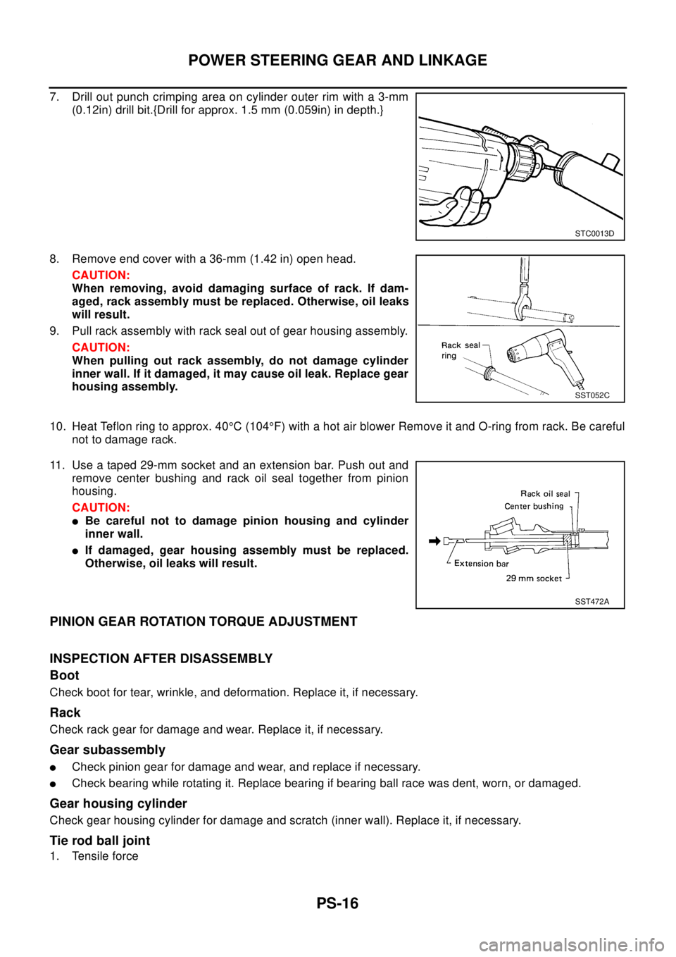
7. Drill out punch crimping area on cylinder outer rim with a 3-mm
(0.12in) drill bit.{Drill for approx. 1.5 mm (0.059in) in depth.}
8. Remove end cover with a 36-mm (1.42 in) open head.
CAUTION:
When removing, avoid damaging surface of rack. If dam-
aged, rack assembly must be replaced. Otherwise, oil leaks
will result.
9. Pull rack assembly with rack seal out of gear housing assembly.
CAUTION:
When pulling out rack assembly, do not damage cylinder
inner wall. If it damaged, it may cause oil leak. Replace gear
housing assembly.
10. Heat Teflon ring to approx. 40°C (104°F) with a hot air blower Remove it and O-ring from rack. Be careful
not to damage rack.
11. Use a taped 29-mm socket and an extension bar. Push out and
remove center bushing and rack oil seal together from pinion
housing.
CAUTION:
lBe careful not to damage pinion housing and cylinder
inner wall.
lIf damaged, gear housing assembly must be replaced.
Otherwise, oil leaks will result.
PINION GEAR ROTATION TORQUE ADJUSTMENT
INSPECTION AFTER DISASSEMBLY
Boot
Check boot for tear, wrinkle, and deformation. Replace it, if necessary.
Rack
Check rack gear for damage and wear. Replace it, if necessary.
Gear subassembly
lCheck pinion gear for damage and wear, and replace if necessary.
lCheck bearing while rotating it. Replace bearing if bearing ball race was dent, worn, or damaged.
Gear housing cylinder
Check gear housing cylinder for damage and scratch (inner wall). Replace it, if necessary.
Tie rod ball joint
1. Tensile force
STC0013D
SST052C
SST472A
Page 2777 of 3066
POWER STEERING GEAR AND LINKAGE
PS-17
C
D
E
F
H
I
J
K
L
MA
B
PS
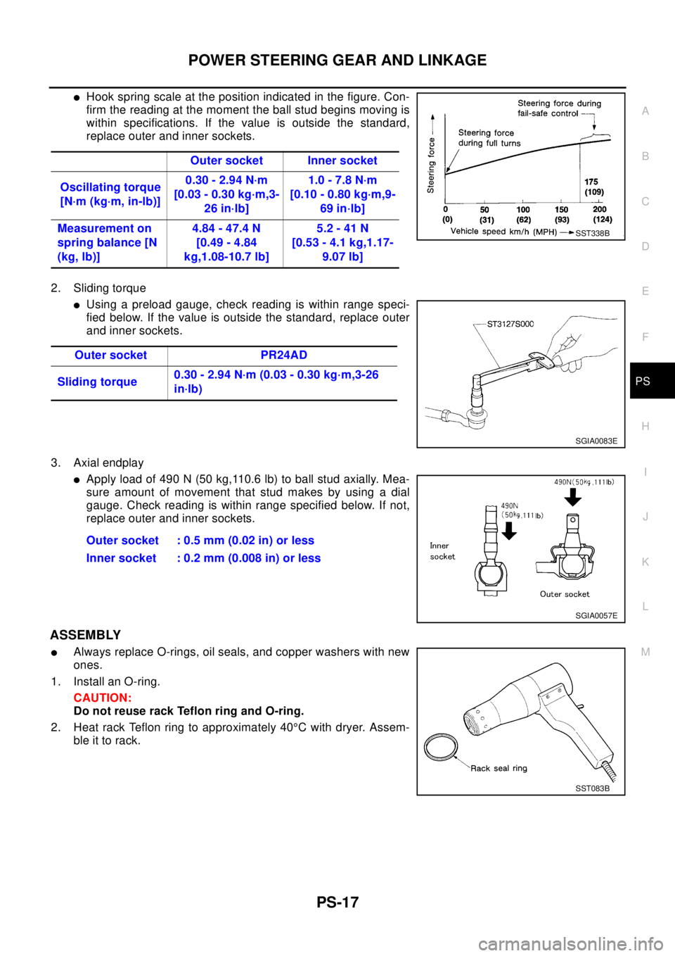
lHook spring scale at the position indicated in the figure. Con-
firm the reading at the moment the ball stud begins moving is
within specifications. If the value is outside the standard,
replace outer and inner sockets.
2. Sliding torque
lUsing a preload gauge, check reading is within range speci-
fied below. If the value is outside the standard, replace outer
and inner sockets.
3. Axial endplay
lApply load of 490 N (50 kg,110.6 lb) to ball stud axially. Mea-
sure amount of movement that stud makes by using a dial
gauge. Check reading is within range specified below. If not,
replace outer and inner sockets.
ASSEMBLY
lAlways replace O-rings, oil seals, and copper washers with new
ones.
1. Install an O-ring.
CAUTION:
Do not reuse rack Teflon ring and O-ring.
2. Heat rack Teflon ring to approximately 40°C with dryer. Assem-
ble it to rack.Outer socket Inner socket
Oscillating torque
[N·m (kg·m, in-lb)]0.30 - 2.94 N·m
[0.03 - 0.30 kg·m,3-
26 in·lb]1.0 - 7.8 N·m
[0.10 - 0.80 kg·m,9-
69 in·lb]
Measurement on
spring balance [N
(kg, lb)]4.84 - 47.4 N
[0.49 - 4.84
kg,1.08-10.7 lb]5.2 - 41 N
[0.53 - 4.1 kg,1.17-
9.07 lb]
SST338B
Outer socket PR24AD
Sliding torque0.30 - 2.94 N·m (0.03 - 0.30 kg·m,3-26
in·lb)
SGIA0083E
Outer socket : 0.5 mm (0.02 in) or less
Inner socket : 0.2 mm (0.008 in) or less
SGIA0057E
SST083B
Page 2783 of 3066
POWER STEERING OIL PUMP
PS-23
C
D
E
F
H
I
J
K
L
MA
B
PS
POWER STEERING OIL PUMPPFP:49110
On-Vehicle Inspection and ServiceEGS000AF
OIL PUMP PULLEY HYDRAULIC PRESSURE INSPECTION
Before starting following procedure, check tension of belt.
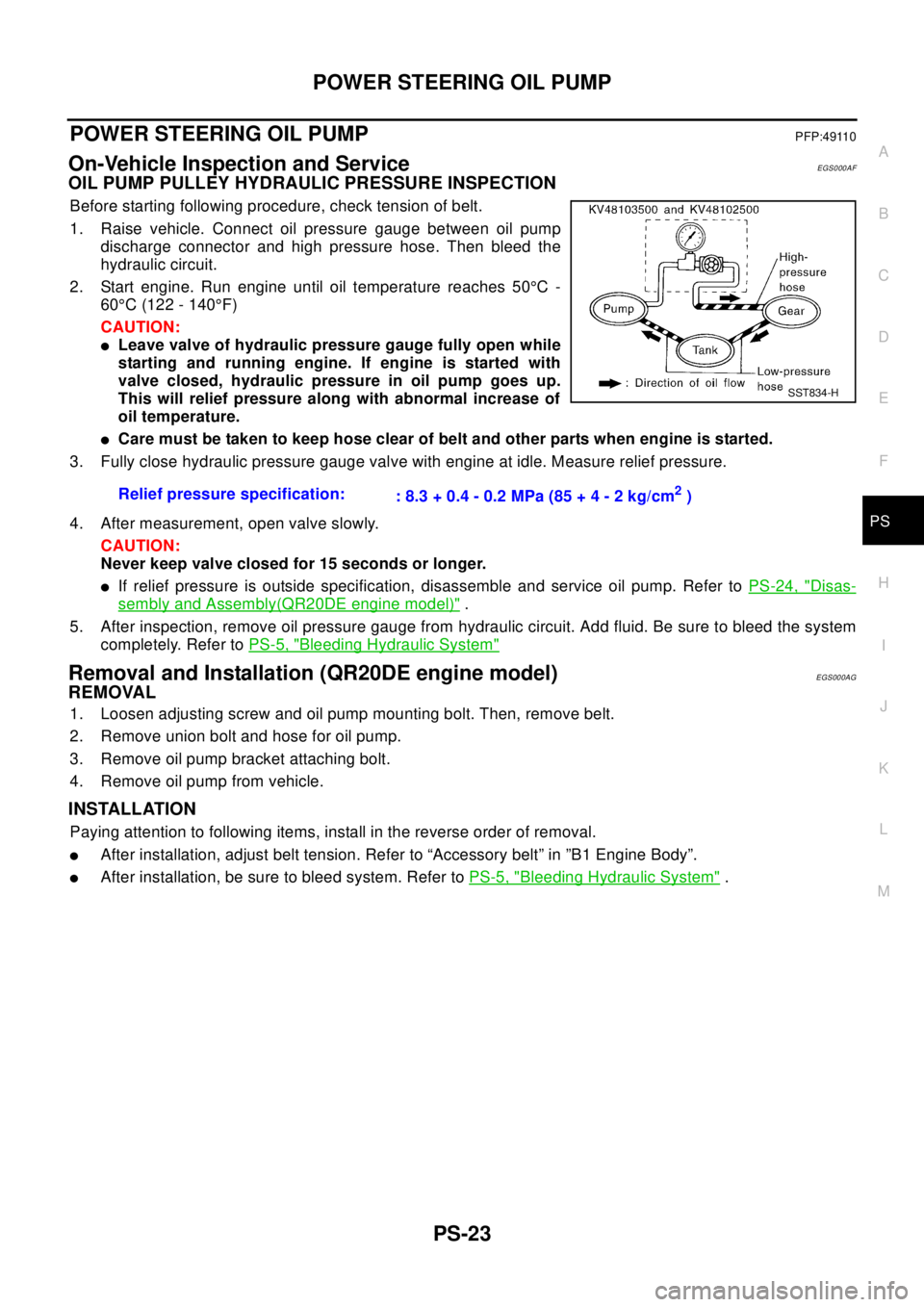
1. Raise vehicle. Connect oil pressure gauge between oil pump
discharge connector and high pressure hose. Then bleed the
hydraulic circuit.
2. Start engine. Run engine until oil temperature reaches 50°C-
60°C (122 - 140°F)
CAUTION:
lLeave valve of hydraulic pressure gauge fully open while
starting and running engine. If engine is started with
valve closed, hydraulic pressure in oil pump goes up.
This will relief pressure along with abnormal increase of
oil temperature.
lCare must be taken to keep hose clear of belt and other parts when engine is started.
3. Fully close hydraulic pressure gauge valve with engine at idle. Measure relief pressure.
4. After measurement, open valve slowly.
CAUTION:
Never keep valve closed for 15 seconds or longer.
lIf relief pressure is outside specification, disassemble and service oil pump. Refer toPS-24, "Disas-
sembly and Assembly(QR20DE engine model)".
5. After inspection, remove oil pressure gauge from hydraulic circuit. Add fluid. Be sure to bleed the system
completely. Refer toPS-5, "
Bleeding Hydraulic System"
Removal and Installation (QR20DE engine model)EGS000AG
REMOVAL
1. Loosen adjusting screw and oil pump mounting bolt. Then, remove belt.
2. Remove union bolt and hose for oil pump.
3. Remove oil pump bracket attaching bolt.
4. Remove oil pump from vehicle.
INSTALLATION
Paying attention to following items, install in the reverse order of removal.
lAfter installation, adjust belt tension. Refer to “Accessory belt” in ”B1 Engine Body”.
lAfter installation, be sure to bleed system. Refer toPS-5, "Bleeding Hydraulic System". Relief pressure specification:
: 8.3 + 0.4 - 0.2 MPa (85 + 4 - 2 kg/cm
2)
SST834-H
Page 2785 of 3066
POWER STEERING OIL PUMP
PS-25
C
D
E
F
H
I
J
K
L
MA
B
PS
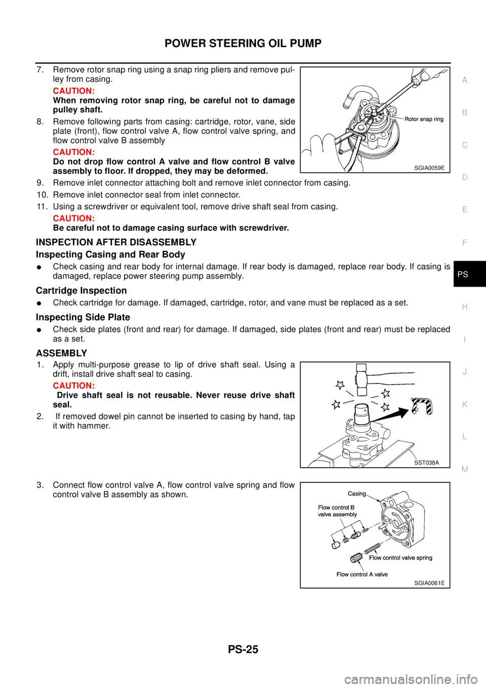
7. Remove rotor snap ring using a snap ring pliers and remove pul-
ley from casing.
CAUTION:
When removing rotor snap ring, be careful not to damage
pulley shaft.
8. Remove following parts from casing: cartridge, rotor, vane, side
plate (front), flow control valve A, flow control valve spring, and
flow control valve B assembly
CAUTION:
Do not drop flow control A valve and flow control B valve
assembly to floor. If dropped, they may be deformed.
9. Remove inlet connector attaching bolt and remove inlet connector from casing.
10. Remove inlet connector seal from inlet connector.
11. Using a screwdriver or equivalent tool, remove drive shaft seal from casing.
CAUTION:
Be careful not to damage casing surface with screwdriver.
INSPECTION AFTER DISASSEMBLY
Inspecting Casing and Rear Body
lCheck casing and rear body for internal damage. If rear body is damaged, replace rear body. If casing is
damaged, replace power steering pump assembly.
Cartridge Inspection
lCheck cartridge for damage. If damaged, cartridge, rotor, and vane must be replaced as a set.
Inspecting Side Plate
lCheck side plates (front and rear) for damage. If damaged, side plates (front and rear) must be replaced
as a set.
ASSEMBLY
1. Apply multi-purpose grease to lip of drive shaft seal. Using a
drift, install drive shaft seal to casing.
CAUTION:
Drive shaft seal is not reusable. Never reuse drive shaft
seal.
2. If removed dowel pin cannot be inserted to casing by hand, tap
it with hammer.
3. Connect flow control valve A, flow control valve spring and flow
control valve B assembly as shown.
SGIA0059E
SST038A
SGIA0061E
Page 2798 of 3066
RAX-2
PRECAUTIONS
PRECAUTIONS
PFP:00001
CautionEDS00060
Observe the following precautions when disassembling and servicing drive shaft.
lPerform work in a location which is as dust-free and dirt-free as possible.
lBefore disassembling and servicing, clean the outside of parts.
lThe disassembly and service location must be clean. Care must be taken to prevent parts from becoming
dirty and to prevent the entry of foreign objects.
lDisassembled parts must be carefully reassembled in the correct order. If work is interrupted, a clean
cover must be placed over parts.
lPaper shop cloths must be used. Fabric shop cloths must not be used because of the danger of lint adher-
ing to parts.
lDisassembled parts (except for rubber parts) should be cleaned with kerosene which shall be removed by
blowing with air or wiping with paper shop cloths.
Precautions for Brake SystemEDS0 00 I2
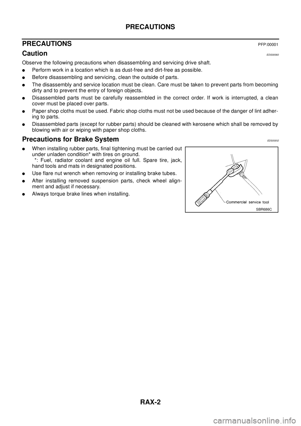
lWhen installing rubber parts, final tightening must be carried out
under unladen condition* with tires on ground.
*: Fuel, radiator coolant and engine oil full. Spare tire, jack,
hand tools and mats in designated positions.
lUse flare nut wrench when removing or installing brake tubes.
lAfter installing removed suspension parts, check wheel align-
ment and adjust if necessary.
lAlways torque brake lines when installing.
SBR686C
Page 2805 of 3066
REAR DRIVE SHAFT
RAX-9
C
E
F
G
H
I
J
K
L
MA
B
RAX
REAR DRIVE SHAFTPFP:39600
Removal and InstallationEDS000FL
REMOVAL
1. Remove rear axle. Refer toRAX-6, "REMOVAL".
NOTE:
In order to remove the rear drive shaft assembly, the rear axle is removed. At this time it is recommended
that front and rear parallel links on axle side be loosened (not removed). This will facilitate wheel align-
ment inspection and adjustment which are carried out later.
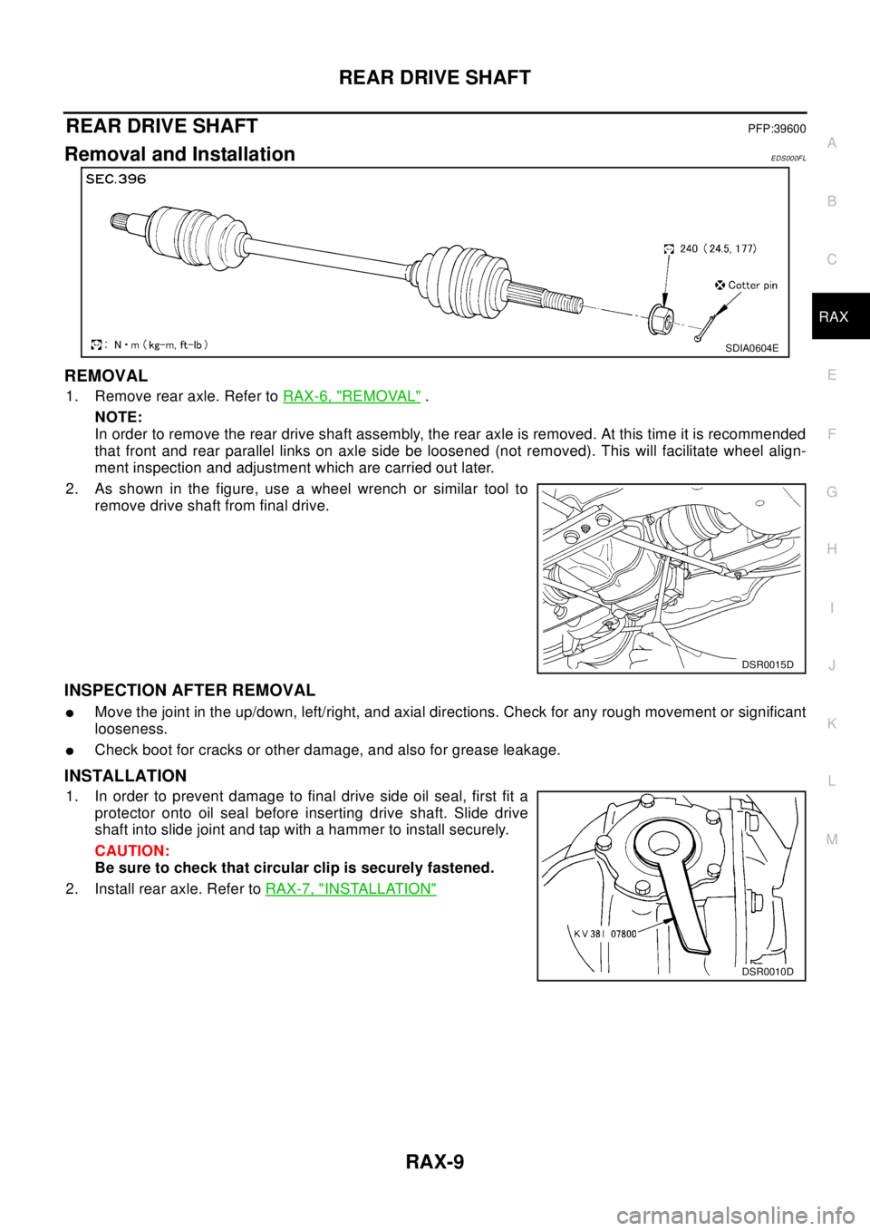
2. As shown in the figure, use a wheel wrench or similar tool to
remove drive shaft from final drive.
INSPECTION AFTER REMOVAL
lMove the joint in the up/down, left/right, and axial directions. Check for any rough movement or significant
looseness.
lCheck boot for cracks or other damage, and also for grease leakage.
INSTALLATION
1. In order to prevent damage to final drive side oil seal, first fit a
protector onto oil seal before inserting drive shaft. Slide drive
shaft into slide joint and tap with a hammer to install securely.
CAUTION:
Be sure to check that circular clip is securely fastened.
2. Install rear axle. Refer toRAX-7, "
INSTALLATION"
SDIA0604E
DSR0015D
DSR0010D
Page 2824 of 3066
RFD-2
PRECAUTIONS
PRECAUTIONS
PFP:00001
CautionEDS00056
lBefore starting diagnosis of the vehicle, understand symptoms well. Perform correct and systematic oper-
ations.
lCheck for the correct installation status prior to removal or disassembly. When mating marks are required,
be sure they do not interfere with the function of the parts they are applied to.
lCarry out an overhaul in a clean work place. Using a dust proof room is recommended.
lBefore disassembly, using steam or white gasoline, completely remove sand and mud from the exterior of
the unit, preventing them from entering into the unit during disassembly or assembly.
lCheck appearance of the disassembled parts for damage, deformation, and abnormal wear. If a malfunc-
tion is detected, replace it with a new one.
lNormally replace lock pins, oil seals, and bearings with new ones every time they are removed.
lIn principle, tighten bolts or nuts gradually in several steps working diagonally from inside to outside. If
tightening sequence is specified, observe it.
lClean and flush the parts sufficiently and blow them dry.
lBe careful not to damage the sliding surfaces and mating surfaces.
lWhen applying sealant, remove the old sealant from the mounting surface; then remove any moisture, oil,
and foreign materials from the application and mounting surfaces.
lAlways use shop paper for cleaning the inside of components.
lAvoid using cotton gloves or a shop cloth to prevent entering of lint.
lDuring assembly, observe the specified tightening torque, and apply new differential oil, Vaseline, or Nis-
san MP Special Grease No. 2, as specified for each vehicle, when necessary.
lDo not reuse drained oil. Discard waste oil after oil changes or part treatment in accordance with local
laws and regulations.
Precautions for Brake SystemEDS000HX
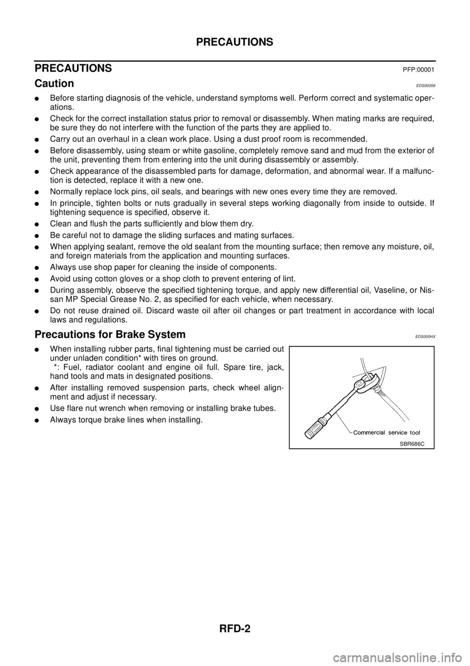
lWhen installing rubber parts, final tightening must be carried out
under unladen condition* with tires on ground.
*: Fuel, radiator coolant and engine oil full. Spare tire, jack,
hand tools and mats in designated positions.
lAfter installing removed suspension parts, check wheel align-
ment and adjust if necessary.
lUse flare nut wrench when removing or installing brake tubes.
lAlways torque brake lines when installing.
SBR686C
Page 2826 of 3066
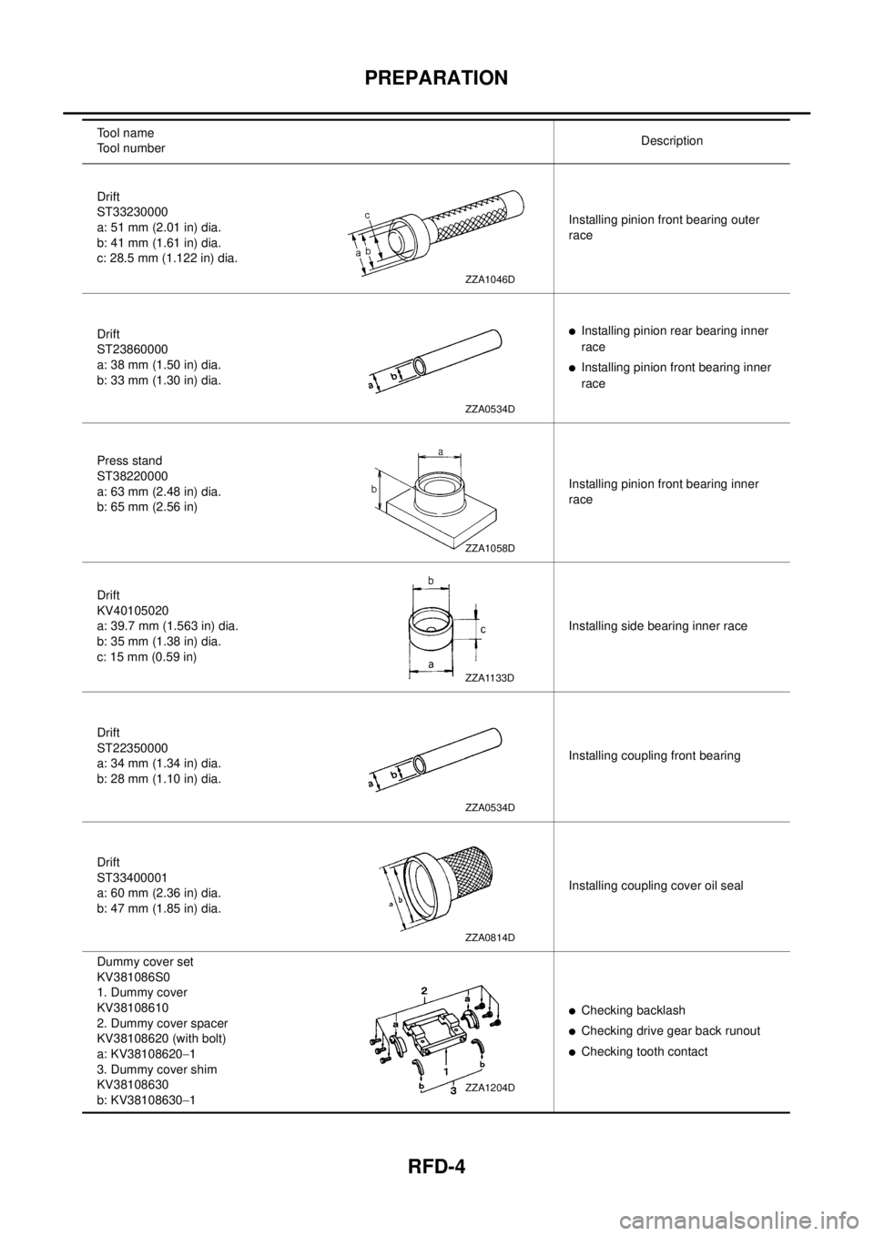
RFD-4
PREPARATION
Drift
ST33230000
a: 51 mm (2.01 in) dia.
b: 41 mm (1.61 in) dia.
c: 28.5 mm (1.122 in) dia.Installing pinion front bearing outer
race
Drift
ST23860000
a: 38 mm (1.50 in) dia.
b: 33 mm (1.30 in) dia.
lInstalling pinion rear bearing inner
race
lInstalling pinion front bearing inner
race
Press stand
ST38220000
a: 63 mm (2.48 in) dia.
b: 65 mm (2.56 in)Installing pinion front bearing inner
race
Drift
KV40105020
a: 39.7 mm (1.563 in) dia.
b: 35 mm (1.38 in) dia.
c: 15 mm (0.59 in)Installing side bearing inner race
Drift
ST22350000
a: 34 mm (1.34 in) dia.
b: 28 mm (1.10 in) dia.Installing coupling front bearing
Drift
ST33400001
a: 60 mm (2.36 in) dia.
b: 47 mm (1.85 in) dia.Installing coupling cover oil seal
Dummy cover set
KV381086S0
1. Dummy cover
KV38108610
2. Dummy cover spacer
KV38108620 (with bolt)
a: KV38108620-1
3. Dummy cover shim
KV38108630
b: KV38108630-1
lChecking backlash
lChecking drive gear back runout
lChecking tooth contact Tool name
Tool numberDescription
ZZA1046D
ZZA0534D
ZZA1058D
ZZA1133D
ZZA0534D
ZZA0814D
ZZA1204D
Page 2828 of 3066
RFD-6
OIL
OIL
PFP:00024
InspectionEDS00059
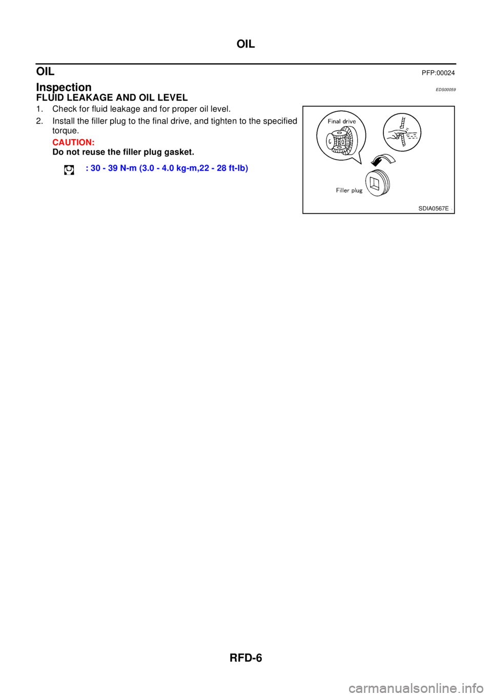
FLUID LEAKAGE AND OIL LEVEL
1. Check for fluid leakage and for proper oil level.
2. Install the filler plug to the final drive, and tighten to the specified
torque.
CAUTION:
Do not reuse the filler plug gasket.
: 30 - 39 N-m (3.0 - 4.0 kg-m,22 - 28 ft-lb)
SDIA0567E