check oil NISSAN X-TRAIL 2003 Electronic Repair Manual
[x] Cancel search | Manufacturer: NISSAN, Model Year: 2003, Model line: X-TRAIL, Model: NISSAN X-TRAIL 2003Pages: 3066, PDF Size: 51.47 MB
Page 2596 of 3066
MT-60
INPUT SHAFT AND GEARS
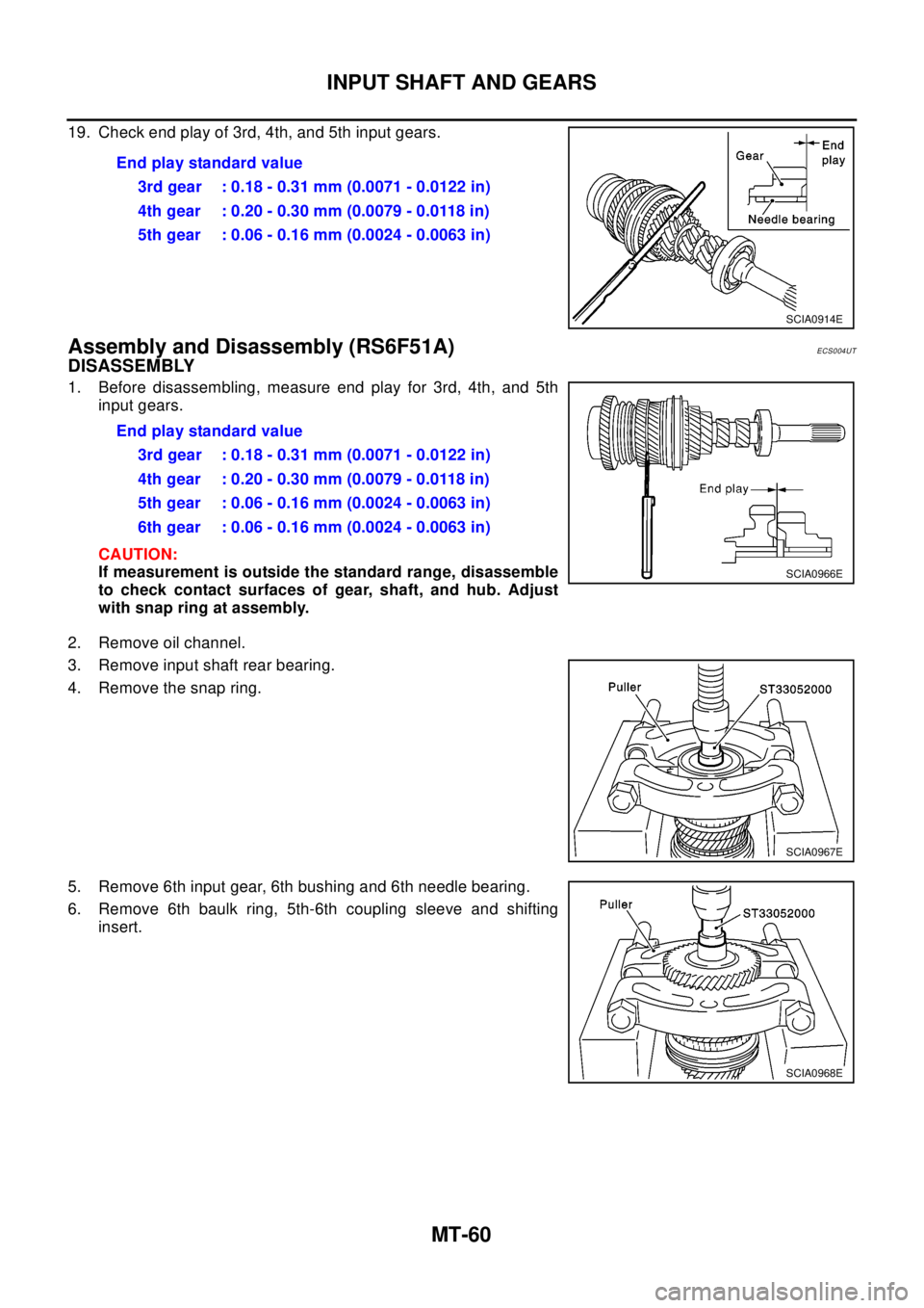
19. Check end play of 3rd, 4th, and 5th input gears.
Assembly and Disassembly (RS6F51A)ECS004UT
DISASSEMBLY
1. Before disassembling, measure end play for 3rd, 4th, and 5th
input gears.
CAUTION:
If measurement is outside the standard range, disassemble
to check contact surfaces of gear, shaft, and hub. Adjust
with snap ring at assembly.
2. Remove oil channel.
3. Remove input shaft rear bearing.
4. Remove the snap ring.
5. Remove 6th input gear, 6th bushing and 6th needle bearing.
6. Remove 6th baulk ring, 5th-6th coupling sleeve and shifting
insert.Endplaystandardvalue
3rd gear : 0.18 - 0.31 mm (0.0071 - 0.0122 in)
4th gear : 0.20 - 0.30 mm (0.0079 - 0.0118 in)
5th gear : 0.06 - 0.16 mm (0.0024 - 0.0063 in)
SCIA0914E
Endplaystandardvalue
3rd gear : 0.18 - 0.31 mm (0.0071 - 0.0122 in)
4th gear : 0.20 - 0.30 mm (0.0079 - 0.0118 in)
5th gear : 0.06 - 0.16 mm (0.0024 - 0.0063 in)
6th gear : 0.06 - 0.16 mm (0.0024 - 0.0063 in)
SCIA0966E
SCIA0967E
SCIA0968E
Page 2602 of 3066
MT-66
INPUT SHAFT AND GEARS
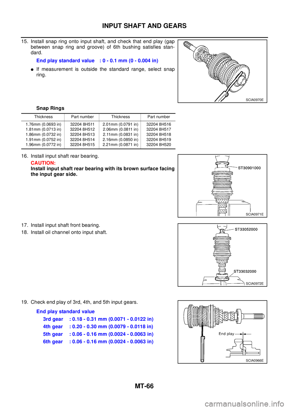
15. Install snap ring onto input shaft, and check that end play (gap
between snap ring and groove) of 6th bushing satisfies stan-
dard.
lIf measurement is outside the standard range, select snap
ring.
Snap Rings
16. Install input shaft rear bearing.
CAUTION:
Install input shaft rear bearing with its brown surface facing
the input gear side.
17. Install input shaft front bearing.
18. Install oil channel onto input shaft.
19. Check end play of 3rd, 4th, and 5th input gears.End play standard value : 0 - 0.1 mm (0 - 0.004 in)
SCIA0970E
Thickness Part number Thickness Part number
1.76mm (0.0693 in)
1.81mm (0.0713 in)
1.86mm (0.0732 in)
1.91mm (0.0752 in)
1.96mm (0.0772 in)32204 8H511
32204 8H512
32204 8H513
32204 8H514
32204 8H5152.01mm (0.0791 in)
2.06mm (0.0811 in)
2.11mm (0.0831 in)
2.16mm (0.0850 in)
2.21mm (0.0871 in)32204 8H516
32204 8H517
32204 8H518
32204 8H519
32204 8H520
SCIA0971E
SCIA0972E
Endplaystandardvalue
3rd gear : 0.18 - 0.31 mm (0.0071 - 0.0122 in)
4th gear : 0.20 - 0.30 mm (0.0079 - 0.0118 in)
5th gear : 0.06 - 0.16 mm (0.0024 - 0.0063 in)
6th gear : 0.06 - 0.16 mm (0.0024 - 0.0063 in)
SCIA0966E
Page 2622 of 3066
MT-86
FINAL DRIVE
FINAL DRIVE
PFP:38411
Assembly and Disassembly (RS5F51A)ECS004UR
PRE-INSPECTION
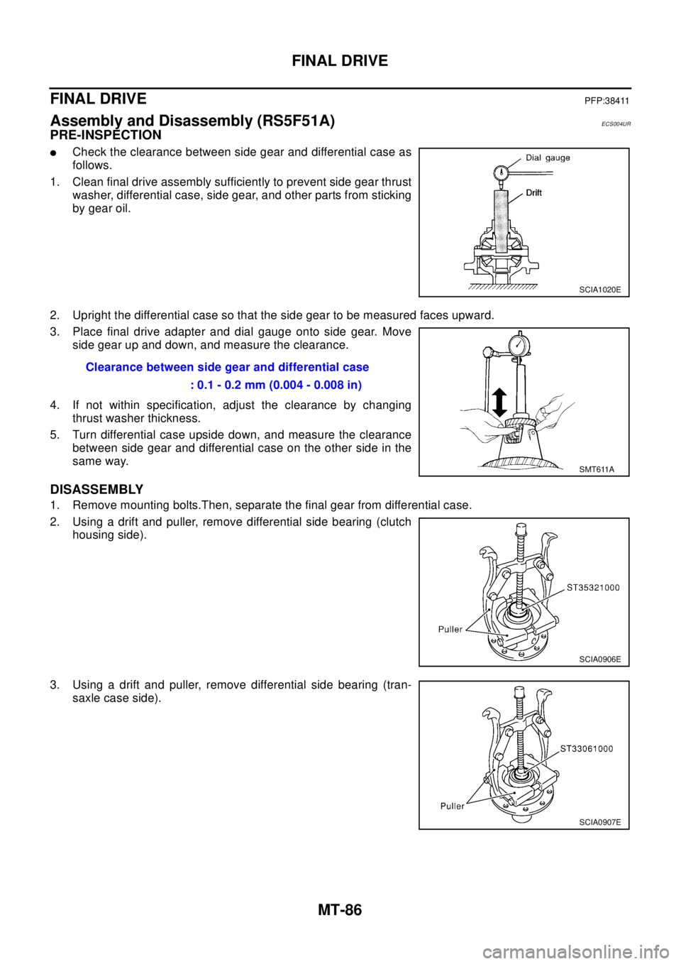
lCheck the clearance between side gear and differential case as
follows.
1. Clean final drive assembly sufficiently to prevent side gear thrust
washer, differential case, side gear, and other parts from sticking
by gear oil.
2. Upright the differential case so that the side gear to be measured faces upward.
3. Place final drive adapter and dial gauge onto side gear. Move
side gear up and down, and measure the clearance.
4. If not within specification, adjust the clearance by changing
thrust washer thickness.
5. Turn differential case upside down, and measure the clearance
between side gear and differential case on the other side in the
same way.
DISASSEMBLY
1. Remove mounting bolts.Then, separate the final gear from differential case.
2. Using a drift and puller, remove differential side bearing (clutch
housing side).
3. Using a drift and puller, remove differential side bearing (tran-
saxle case side).
SCIA1020E
Clearance between side gear and differential case
: 0.1 - 0.2 mm (0.004 - 0.008 in)
SMT611A
SCIA0906E
SCIA0907E
Page 2623 of 3066
FINAL DRIVE
MT-87
D
E
F
G
H
I
J
K
L
MA
B
MT
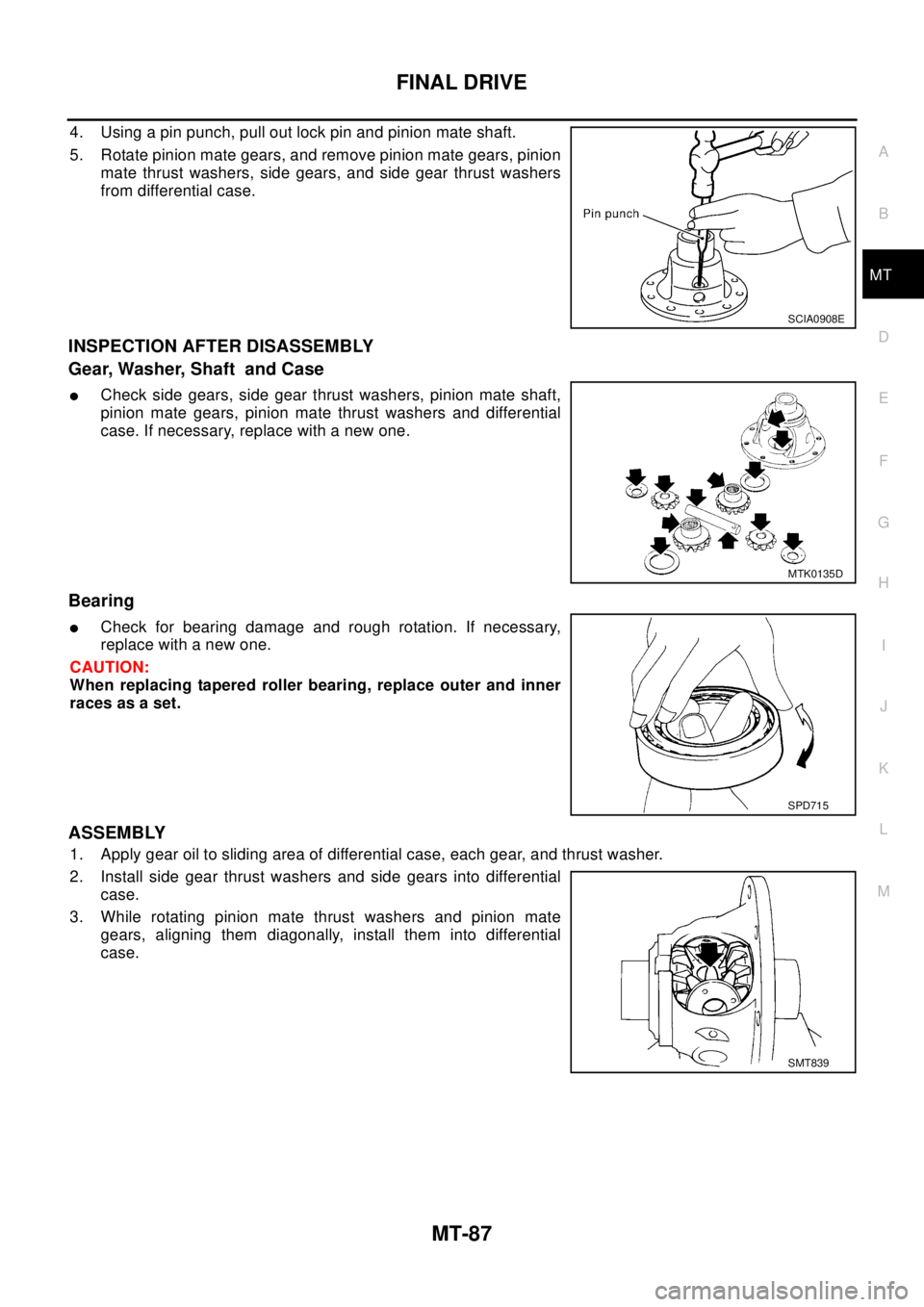
4. Using a pin punch, pull out lock pin and pinion mate shaft.
5. Rotate pinion mate gears, and remove pinion mate gears, pinion
mate thrust washers, side gears, and side gear thrust washers
from differential case.
INSPECTION AFTER DISASSEMBLY
Gear, Washer, Shaft and Case
lCheck side gears, side gear thrust washers, pinion mate shaft,
pinion mate gears, pinion mate thrust washers and differential
case. If necessary, replace with a new one.
Bearing
lCheck for bearing damage and rough rotation. If necessary,
replace with a new one.
CAUTION:
When replacing tapered roller bearing, replace outer and inner
races as a set.
ASSEMBLY
1. Apply gear oil to sliding area of differential case, each gear, and thrust washer.
2. Install side gear thrust washers and side gears into differential
case.
3. While rotating pinion mate thrust washers and pinion mate
gears, aligning them diagonally, install them into differential
case.
SCIA0908E
MTK0135D
SPD715
SMT839
Page 2625 of 3066
FINAL DRIVE
MT-89
D
E
F
G
H
I
J
K
L
MA
B
MT
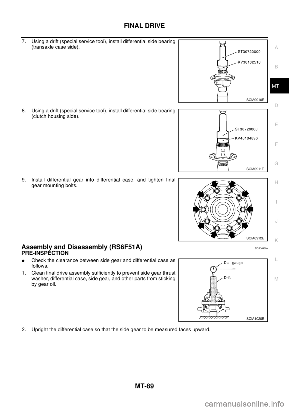
7. Using a drift (special service tool), install differential side bearing
(transaxle case side).
8. Using a drift (special service tool), install differential side bearing
(clutch housing side).
9. Install differential gear into differential case, and tighten final
gear mounting bolts.
Assembly and Disassembly (RS6F51A)ECS004UW
PRE-INSPECTION
lCheck the clearance between side gear and differential case as
follows.
1. Clean final drive assembly sufficiently to prevent side gear thrust
washer, differential case, side gear, and other parts from sticking
by gear oil.
2. Upright the differential case so that the side gear to be measured faces upward.
SCIA0910E
SCIA0911E
SCIA0912E
SCIA1020E
Page 2627 of 3066
FINAL DRIVE
MT-91
D
E
F
G
H
I
J
K
L
MA
B
MT
INSPECTION AFTER DISASSEMBLY
Gear, Washer, Shaft and Case
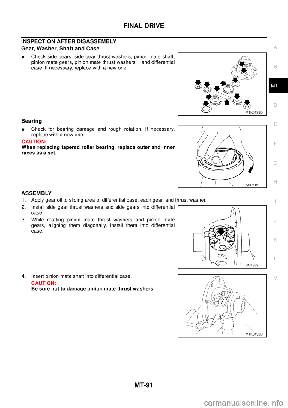
lCheck side gears, side gear thrust washers, pinion mate shaft,
pinion mate gears, pinion mate thrust washers and differential
case. If necessary, replace with a new one.
Bearing
lCheck for bearing damage and rough rotation. If necessary,
replace with a new one.
CAUTION:
When replacing tapered roller bearing, replace outer and inner
races as a set.
ASSEMBLY
1. Apply gear oil to sliding area of differential case, each gear, and thrust washer.
2. Install side gear thrust washers and side gears into differential
case.
3. While rotating pinion mate thrust washers and pinion mate
gears, aligning them diagonally, install them into differential
case.
4. Insert pinion mate shaft into differential case.
CAUTION:
Be sure not to damage pinion mate thrust washers.
MTK0135D
SPD715
SMT839
MTK0132D
Page 2761 of 3066

PS-1
POWER STEERING SYSTEM
G STEERING
CONTENTS
C
D
E
F
H
I
J
K
L
M
SECTION
A
B
PS
POWER STEERING SYSTEM
PRECAUTIONS .......................................................... 2
Precautions for models with SRS air bag and pre-
tensioner seat belt .................................................... 2
Caution ..................................................................... 2
PREPARATION ........................................................... 3
Special Service Tools ............................................... 3
NOISE, VIBRATION, AND HARSHNESS (NVH)
TROUBLESHOOTING ................................................ 4
NVH Trouble shooting Chart .................................... 4
POWER STEERING FLUID ........................................ 5
Checking Fluid Level ................................................ 5
Checking Fluid Leak ................................................. 5
Bleeding Hydraulic System ...................................... 5
STEERING WHEEL .................................................... 6
On-Vehicle Inspection and Service .......................... 6
PLAY INSPECTION .............................................. 6
NEUTRAL POSITION INSPECTION .................... 6
STEERING TORQUE CHECK .............................. 6
STEERING ANGLE INSPECTION ........................ 6
Removal and Installation .......................................... 7
REMOVAL ............................................................. 7
INSTALLATION ..................................................... 7
STEERING COLUMN ................................................. 9
Removal and Installation .......................................... 9
REMOVAL OF LOWER JOINT AND HOLE
COVER ................................................................. 9
INSTALLATION OF LOWER JOINT AND HOLE
COVER ................................................................. 9
REMOVAL OF STEERING COLUMN ASSEM-
BLY ........................................................................ 9
INSTALLING STEERING COLUMN ASSEMBLY... 10
Disassembly and Assembly ................................... 10
DISASSEMBLY ................................................... 10
INSPECTION AFTER DISASSEMBLY. ...............11
ASSEMBLY ..........................................................11
POWER STEERING GEAR AND LINKAGE ............ 12
Removal and Installation ........................................ 12
REMOVAL ........................................................... 12
INSTALLATION ................................................... 12Components ........................................................... 14
MODEL PR24AD ................................................. 14
Disassembly and Assembly .................................... 15
DISASSEMBLY ................................................... 15
PINION GEAR ROTATION TORQUE ADJUST-
MENT .................................................................. 16
INSPECTION AFTER DISASSEMBLY ................ 16
ASSEMBLY ......................................................... 17
POWER STEERING OIL PUMP ............................... 23
On-Vehicle Inspection and Service ......................... 23
OIL PUMP PULLEY HYDRAULIC PRESSURE
INSPECTION ...................................................... 23
Removal and Installation (QR20DE engine model)... 23
REMOVAL ........................................................... 23
INSTALLATION ................................................... 23
Disassembly and Assembly(QR20DE engine
model) ..................................................................... 24
INSPECTION BEFORE DISASSEMBLY ............. 24
DISASSEMBLY ................................................... 24
INSPECTION AFTER DISASSEMBLY ................ 25
ASSEMBLY ......................................................... 25
Removal and Installation (YD22DDTi engine
model) ..................................................................... 28
Disassembly and Assembly (YD22DDTi engine
model) ..................................................................... 29
INSPECTION BEFORE DISASSEMBLY ............. 29
DISASSEMBLY ................................................... 30
INSPECTION AFTER DISASSEMBLY ................ 31
ASSEMBLY ......................................................... 31
HYDRAULIC LINE .................................................... 33
Removal and Installation ........................................ 33
SERVICE DATA AND SPECIFICATIONS (SDS) ...... 35
Wheel ..................................................................... 35
Steering Angle ........................................................ 35
Steering Column ..................................................... 35
Steering Linkage ..................................................... 35
Steering Gear ......................................................... 36
Oil Pump ................................................................. 36
Steering Fluid .......................................................... 36
Page 2762 of 3066

PS-2
PRECAUTIONS
PRECAUTIONS
PFP:00001
Precautions for models with SRS air bag and pre-tensioner seat beltEGS00048
WAR NIN G:
lBefore removing and installing components and harnesses of SRS air bag and seat belt pre-ten-
sioner system, turn ignition switch OFF, disconnect battery ground cable, and wait at least 3 min-
utes. (This discharges electricity held in the air bag sensor unit's additional power circuit.)
lDo not use pneumatic or electric tools to remove and install the components.
lDo not solder SRS air bag and seat belt pre-tensioner system harnesses when making repairs.
Make sure harness is not pinched and there is no contact with other components.
lWhen checking the SRS air bag and the seat belt pre-tensioner circuit or the components of each
system, do not use an electric tester such as a circuit tester. (This is to prevent accidental trigger-
ing caused by the weak electric current of a tester.)
lNever insert foreign material (such as a screwdriver) in the air bag module and pre-tensioner seat
belt connectors. (The units may be actuated by mistake by static electricity.)
lSeat belt pre-tensioner and SRS air bag harnesses can be distinguished from other harnesses by
their yellow connectors.
lWhen servicing, refer to “SB Seat Belt” and “SRS Air Bag” for safety.
CautionEGS00049
lAlways follow the warnings and the cautions below in disassembly procedures:
–Work in a clean, dust-free place. No dust proof device is necessary.
–Clean outside of unit before disassembly.
–Clean parts to be disassembled. Be careful not to allow any dirt or other foreign materials to enter or con-
tact with parts.
–Assemble disassembled parts properly, following order shown in manual. If work has been suspended in
the middle of assembly, place a clean cover over parts. This will prevent them from being contaminated.
–Use paper towels when removing dirt and other foreign materials. Cloth shop towels can leave lint on
cleaned parts that might affect operation of parts.
–Clean disassembled parts (except rubber parts) with kerosene. Drain oil by blowing with air or absorbing
with shop papers.
–Before assembling, apply Nissan power steering fluid to O-rings and seals.
–Replace gaskets and O-rings with new ones. Be careful not to damage any O-rings, oil seals, and gaskets
during assembly.
lIf following part is scratched after disassembly of steering pump, replace applicable part: case, rear body,
side plate, pulley, rotor, vane, or flow control valve
lMark source of fluid leak with a white marker for identification.
lSeals and copper washers must not be reused.
Page 2763 of 3066
PREPARATION
PS-3
C
D
E
F
H
I
J
K
L
MA
B
PS
PREPARATIONPFP:00002
Special Service ToolsEGS0004A
Tool name Description
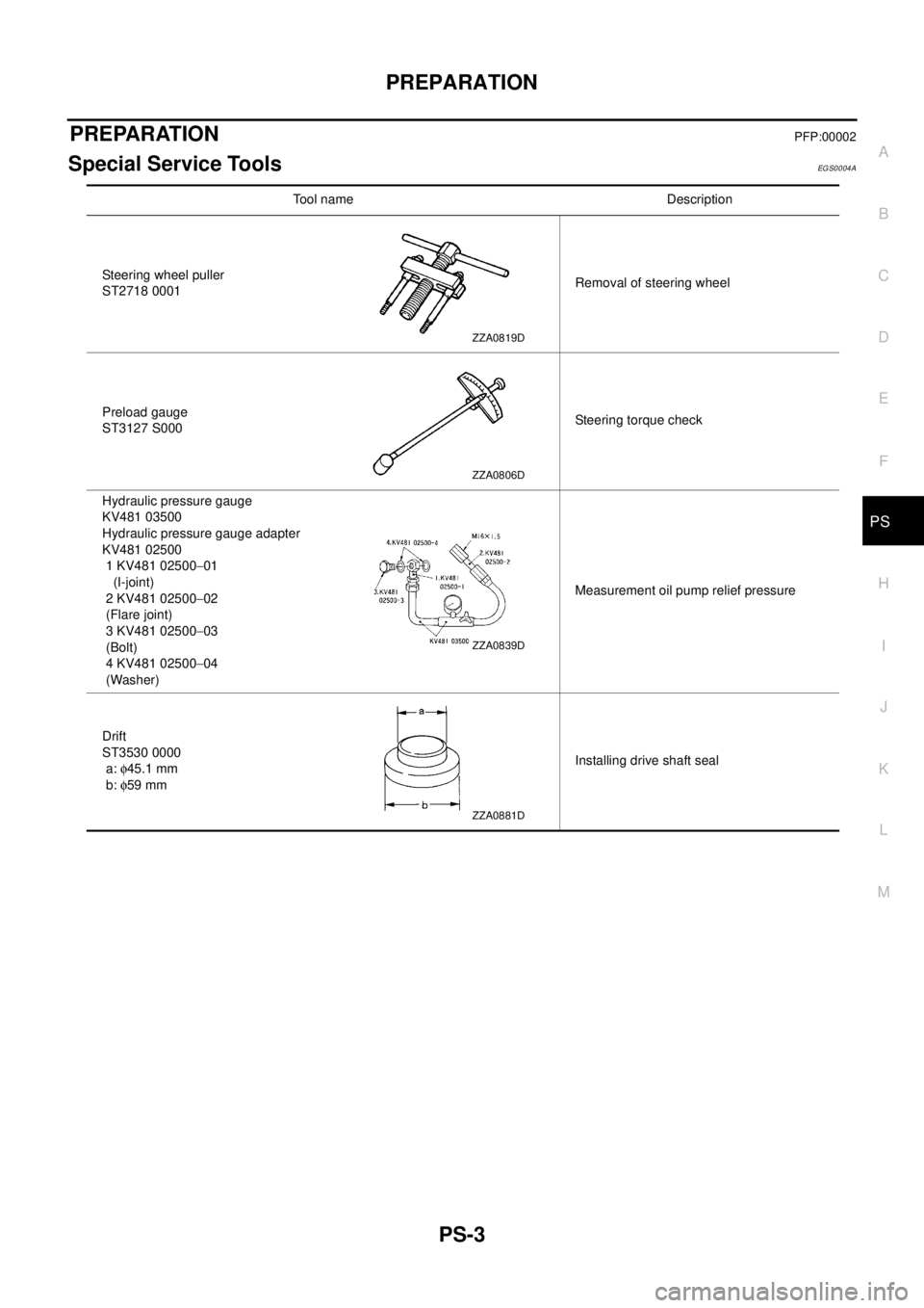
Steering wheel puller
ST2718 0001Removal of steering wheel
Preload gauge
ST3127 S000Steering torque check
Hydraulic pressure gauge
KV481 03500
Hydraulic pressure gauge adapter
KV481 02500
1 KV481 02500-01
(I-joint)
2 KV481 02500-02
(Flare joint)
3 KV481 02500-03
(Bolt)
4 KV481 02500-04
(Washer)Measurement oil pump relief pressure
Drift
ST3530 0000
a:f45.1 mm
b:f59 mmInstalling drive shaft seal
ZZA0819D
ZZA0806D
ZZA0839D
ZZA0881D
Page 2765 of 3066
POWER STEERING FLUID
PS-5
C
D
E
F
H
I
J
K
L
MA
B
PS
POWER STEERING FLUIDPFP:KLF20
Checking Fluid LevelEGS0004B
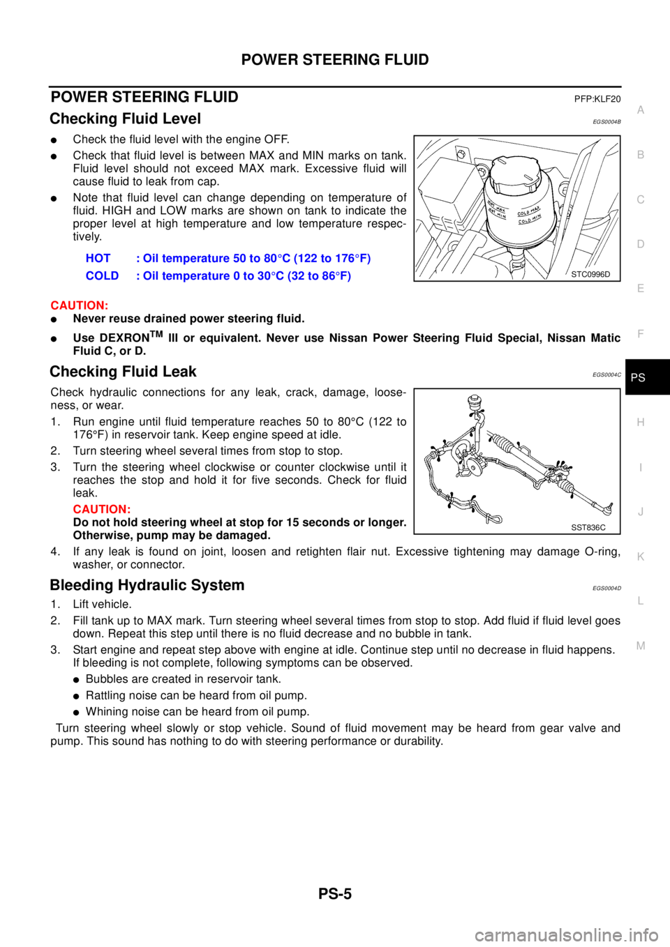
lCheck the fluid level with the engine OFF.
lCheck that fluid level is between MAX and MIN marks on tank.
Fluid level should not exceed MAX mark. Excessive fluid will
cause fluid to leak from cap.
lNote that fluid level can change depending on temperature of
fluid. HIGH and LOW marks are shown on tank to indicate the
proper level at high temperature and low temperature respec-
tively.
CAUTION:
lNever reuse drained power steering fluid.
lUse DEXRONTMIII or equivalent. Never use Nissan Power Steering Fluid Special, Nissan Matic
Fluid C, or D.
Checking Fluid LeakEGS0004C
Check hydraulic connections for any leak, crack, damage, loose-
ness, or wear.
1. Run engine until fluid temperature reaches 50 to 80°C (122 to
176°F) in reservoir tank. Keep engine speed at idle.
2. Turn steering wheel several times from stop to stop.
3. Turn the steering wheel clockwise or counter clockwise until it
reaches the stop and hold it for five seconds. Check for fluid
leak.
CAUTION:
Do not hold steering wheel at stop for 15 seconds or longer.
Otherwise, pump may be damaged.
4. If any leak is found on joint, loosen and retighten flair nut. Excessive tightening may damage O-ring,
washer, or connector.
Bleeding Hydraulic SystemEGS0004D
1. Lift vehicle.
2. Fill tank up to MAX mark. Turn steering wheel several times from stop to stop. Add fluid if fluid level goes
down. Repeat this step until there is no fluid decrease and no bubble in tank.
3. Start engine and repeat step above with engine at idle. Continue step until no decrease in fluid happens.
If bleeding is not complete, following symptoms can be observed.
lBubbles are created in reservoir tank.
lRattling noise can be heard from oil pump.
lWhiningnoisecanbeheardfromoilpump.
Turn steering wheel slowly or stop vehicle. Sound of fluid movement may be heard from gear valve and
pump. This sound has nothing to do with steering performance or durability.HOT : Oil temperature 50 to 80°C (122 to 176°F)
COLD : Oil temperature 0 to 30°C(32to86°F)
STC0996D
SST836C