wheel alignment NISSAN X-TRAIL 2003 Electronic Owner's Manual
[x] Cancel search | Manufacturer: NISSAN, Model Year: 2003, Model line: X-TRAIL, Model: NISSAN X-TRAIL 2003Pages: 3066, PDF Size: 51.47 MB
Page 2767 of 3066
STEERING WHEEL
PS-7
C
D
E
F
H
I
J
K
L
MA
B
PS
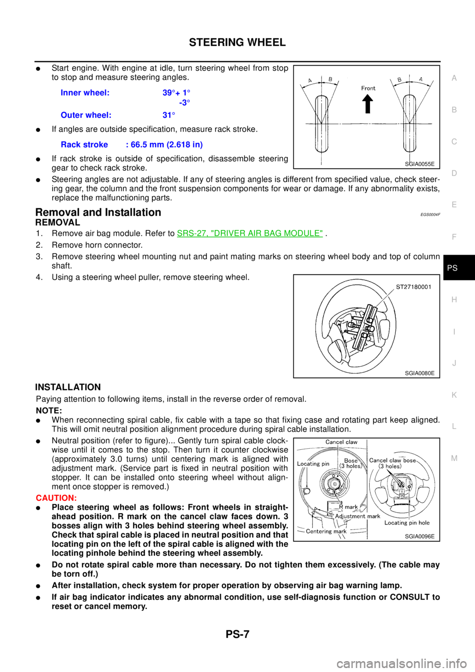
lStart engine. With engine at idle, turn steering wheel from stop
to stop and measure steering angles.
lIf angles are outside specification, measure rack stroke.
lIf rack stroke is outside of specification, disassemble steering
gear to check rack stroke.
lSteering angles are not adjustable. If any of steering angles is different from specified value, check steer-
ing gear, the column and the front suspension components for wear or damage. If any abnormality exists,
replace the malfunctioning parts.
Removal and InstallationEGS0004F
REMOVAL
1. Remove air bag module. Refer toSRS-27, "DRIVER AIR BAG MODULE".
2. Remove horn connector.
3. Remove steering wheel mounting nut and paint mating marks on steering wheel body and top of column
shaft.
4. Using a steering wheel puller, remove steering wheel.
INSTALLATION
Paying attention to following items, install in the reverse order of removal.
NOTE:
lWhen reconnecting spiral cable, fix cable with a tape so that fixing case and rotating part keep aligned.
This will omit neutral position alignment procedure during spiral cable installation.
lNeutral position (refer to figure)... Gently turn spiral cable clock-
wise until it comes to the stop. Then turn it counter clockwise
(approximately 3.0 turns) until centering mark is aligned with
adjustment mark. (Service part is fixed in neutral position with
stopper. It can be installed onto steering wheel without align-
ment once stopper is removed.)
CAUTION:
lPlace steering wheel as follows: Front wheels in straight-
ahead position. R mark on the cancel claw faces down. 3
bosses align with 3 holes behind steering wheel assembly.
Check that spiral cable is placed in neutral position and that
locating pin on the left of the spiral cable is aligned with the
locating pinhole behind the steering wheel assembly.
lDo not rotate spiral cable more than necessary. Do not tighten them excessively. (The cable may
be torn off.)
lAfter installation, check system for proper operation by observing air bag warning lamp.
lIf air bag indicator indicates any abnormal condition, use self-diagnosis function or CONSULT to
reset or cancel memory.Inner wheel: 39°+1°
-3°
Outer wheel: 31°
Rack stroke : 66.5 mm (2.618 in)
SGIA0055E
SGIA0080E
SGIA0096E
Page 2806 of 3066
RAX-10
REAR DRIVE SHAFT
Disassembly and Assembly
EDS000FM
DISASSEMBLY
Final Drive Side
1. Remove boot bands.
2. Fix shaft to bench vise.
CAUTION:
When fixing shaft to bench vise, be sure to protect it with a copper or aluminum sheet.
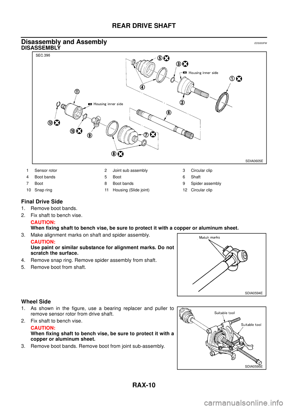
3. Make alignment marks on shaft and spider assembly.
CAUTION:
Use paint or similar substance for alignment marks. Do not
scratch the surface.
4. Remove snap ring. Remove spider assembly from shaft.
5. Remove boot from shaft.
Wheel Side
1. As shown in the figure, use a bearing replacer and puller to
remove sensor rotor from drive shaft.
2. Fix shaft to bench vise.
CAUTION:
When fixing shaft to bench vise, be sure to protect it with a
copper or aluminum sheet.
3. Remove boot bands. Remove boot from joint sub-assembly.
SDIA0605E
1 Sensor rotor 2 Joint sub assembly 3 Circular clip
4 Boot bands 5 Boot 6 Shaft
7 Boot 8 Boot bands 9 Spider assembly
10 Snap ring 11 Housing (Slide joint) 12 Circular clip
SDIA0594E
SDIA0595E
Page 2853 of 3066
RSU-1
REAR SUSPENSION
E SUSPENSION
CONTENTS
C
D
F
G
H
I
J
K
L
M
SECTION
A
B
RSU
REAR SUSPENSION
PRECAUTIONS .......................................................... 2
Caution ..................................................................... 2
Precautions for Brake System .................................. 2
PREPARATION ........................................................... 3
Special Service Tool ................................................. 3
Commercial Service Tools ........................................ 3
NOISE, VIBRATION, AND HARSHNESS (NVH)
TROUBLESHOOTING ................................................ 4
NVH Troubleshooting Chart ..................................... 4
REAR SUSPENSION ASSEMBLY ............................. 5
Components ............................................................. 5
On-Vehicle Inspection and Service .......................... 6
Wheel Alignment ...................................................... 6
DESCRIPTION ...................................................... 6
PRELIMINARY INSPECTION ............................... 6
CAMBER ............................................................... 6
TOE-IN .................................................................. 6
COIL SPRING AND STRUT ....................................... 8
Removal and Installation .......................................... 8
REMOVAL ............................................................. 8
INSTALLATION ..................................................... 8
Disassembly and Assembly ..................................... 8
DISASSEMBLY ..................................................... 8
INSPECTION AFTER DISASSEMBLY ................. 8
ASSEMBLY ........................................................... 9FRONT PARALLEL LINK ......................................... 10
Removal and Installation ........................................ 10
REMOVAL ........................................................... 10
INSPECTION AFTER REMOVAL ....................... 10
INSTALLATION ................................................... 10
REAR PARALLEL LINK ........................................... 11
Removal and Installation ........................................ 11
REMOVAL ........................................................... 11
INSPECTION AFTER REMOVAL ....................... 11
INSTALLATION ................................................... 11
RADIUS ROD ............................................................ 12
Removal and Installation ........................................ 12
REMOVAL ........................................................... 12
INSPECTION AFTER REMOVAL ....................... 12
INSTALLATION ................................................... 12
REAR SUSPENSION MEMBER ............................... 13
Removal and Installation ........................................ 13
REMOVAL ........................................................... 13
INSTALLATION ................................................... 13
SERVICE DATA AND SPECIFICATIONS (SDS) ...... 14
General Specification ............................................. 14
Wheel Alignment (Unladen) .................................... 14
Wheelarch Height (Unladen) .................................. 14
Page 2854 of 3066
RSU-2
PRECAUTIONS
PRECAUTIONS
PFP:00001
CautionEES0007C
lFinal tightening of bushings must be carried out under unladen condition with tires on the ground. Oil will
shorten life of bushings. Be sure to wipe off any spilled oil.
l“Unladen condition” means that fuel, coolant and lubricant are full and ready for drive. However, spare tire,
jack, and hand tools should be unloaded.
lAfter installing the removed suspension parts, always check wheel alignment and adjust if necessary.
lReplace the caulking nut with a new one. Install a new nut without wiping the oil off before tightening.
Precautions for Brake SystemEES000JB
lWhen installing rubber parts, final tightening must be carried out
under unladen condition* with tires on ground.
*: Fuel, radiator coolant and engine oil full. Spare tire, jack,
hand tools and mats in designated positions.
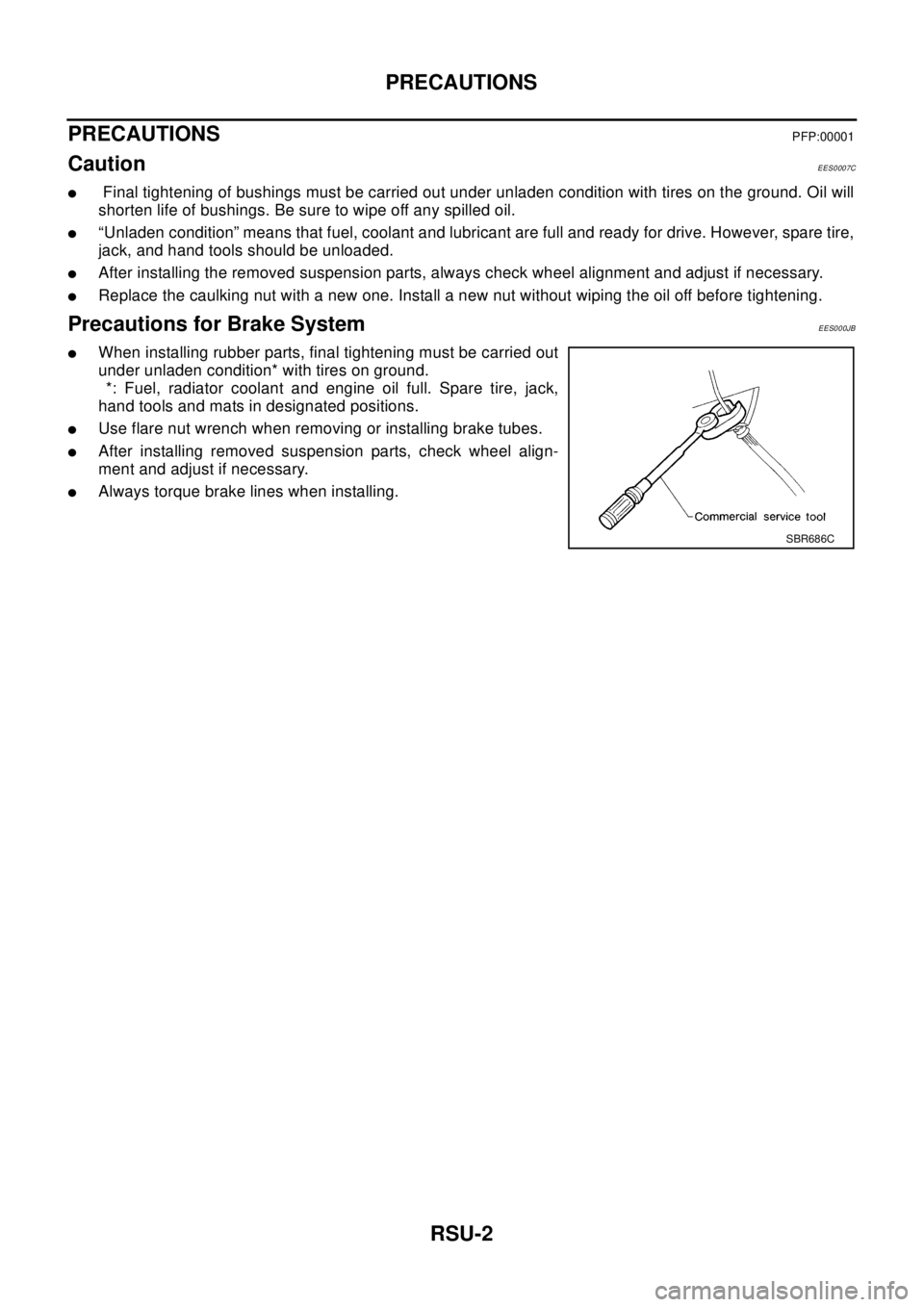
lUse flare nut wrench when removing or installing brake tubes.
lAfter installing removed suspension parts, check wheel align-
ment and adjust if necessary.
lAlways torque brake lines when installing.
SBR686C
Page 2856 of 3066
RSU-4
NOISE, VIBRATION, AND HARSHNESS (NVH) TROUBLESHOOTING
NOISE, VIBRATION, AND HARSHNESS (NVH) TROUBLESHOOTING
PFP:00003
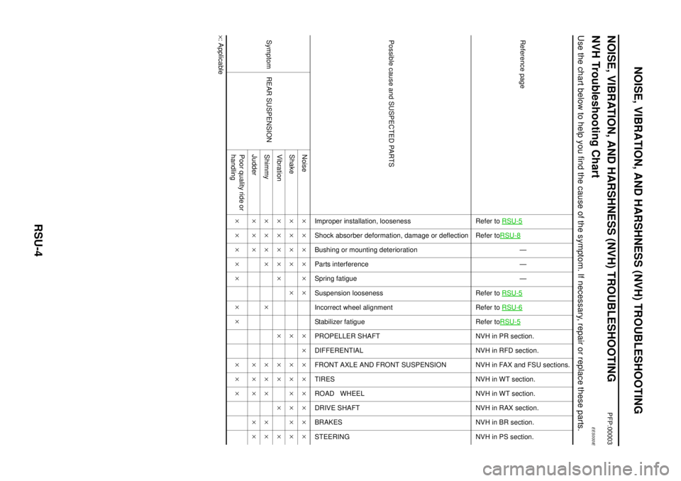
NVH Troubleshooting ChartEES000IE
Use the chart below to help you find the cause of the symptom. If necessary, repair or replace these parts.
´: ApplicableReference page
Refer toRSU-5Refer toRSU-8
—
—
—
Refer toRSU-5
Refer toRSU-6Refer toRSU-5NVHinPRsection.
NVH in RFD section.
NVH in FAX and FSU sections.
NVH in WT section.
NVH in WT section.
NVH in RAX section.
NVHinBRsection.
NVH in PS section.
Possible cause and SUSPECTED PARTS
Improper installation, looseness
Shock absorber deformation, damage or deflection
Bushing or mounting deterioration
Parts interference
Spring fatigue
Suspension looseness
Incorrect wheel alignment
Stabilizer fatigue
PROPELLER SHAFT
DIFFERENTIAL
FRONT AXLE AND FRONT SUSPENSION
TIRES
ROAD WHEEL
DRIVE SHAFT
BRAKES
STEERING
Symptom REAR SUSPENSIONNoise´´´´´´ ´´´´´´´´
Shake´´´´ ´ ´ ´´´´´´
Vibration´´´´´ ´ ´´ ´ ´
Shimmy´´´´ ´ ´´´ ´´
Judder´´´ ´´´ ´´
Poor quality ride or
handling´´´´´ ´´ ´´´
Page 2858 of 3066
RSU-6
REAR SUSPENSION ASSEMBLY
On-Vehicle Inspection and Service
EES0007F
Check axle and suspension parts for excessive play, wear, and damage.
lMove rear wheels (RH/LH) to check abnormal free play.
lRetighten all nuts and bolts to the specified torque.
lCheck strut for oil leakage and damage.
Wheel AlignmentEES0007G
DESCRIPTION
lMeasure wheel alignment under unladen conditions. “Unladen conditions” means that fuel, coolant, and
lubricant are full. However, spare tire, jack, and hand tools should be unloaded.
PRELIMINARY INSPECTION
1. Check the tires for improper air pressure and wear.
2. Check road wheels for runout.
3. Check wheel bearing axial endplay.
4. Check strut operation.
5. Check each mounting point of axle and suspension for looseness and deformation.
6. Check each link and arm for cracks, deformation, and other damage.
7. Check the vehicle posture.
CAMBER
Camber is preset at factory and cannot be adjusted.
lIf the camber is not within specification, inspect and replace any damaged or worn rear suspension parts.
TOE-IN
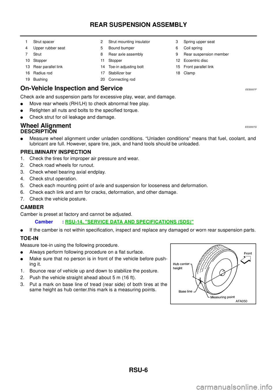
Measure toe-in using the following procedure.
lAlways perform following procedure on a flat surface.
lMake sure that no person is in front of the vehicle before push-
ing it.
1. Bounce rear of vehicle up and down to stabilize the posture.
2. Push the vehicle straight ahead about 5 m (16 ft).
3. Put a mark on base line of tread (rear side) of both tires at the
same height as hub center.this mark is a measuring points.
1 Strut spacer 2 Strut mounting insulator 3 Spring upper seat
4 Upper rubber seat 5 Bound bumper 6 Coil spring
7 Strut 8 Rear axle assembly 9 Rear suspension member
10 Stopper 11 Stopper 12 Eccentric disc
13 Rear parallel link 14 Toe-in adjusting bolt 15 Front parallel link
16 Radius rod 17 Stabilizer bar 18 Clamp
19 Bushing 20 Connecting rod
Camber :RSU-14, "SERVICE DATA AND SPECIFICATIONS (SDS)"
AFA050
Page 2865 of 3066
REAR SUSPENSION MEMBER
RSU-13
C
D
F
G
H
I
J
K
L
MA
B
RSU
REAR SUSPENSION MEMBERPFP:55501
Removal and InstallationEES0007M
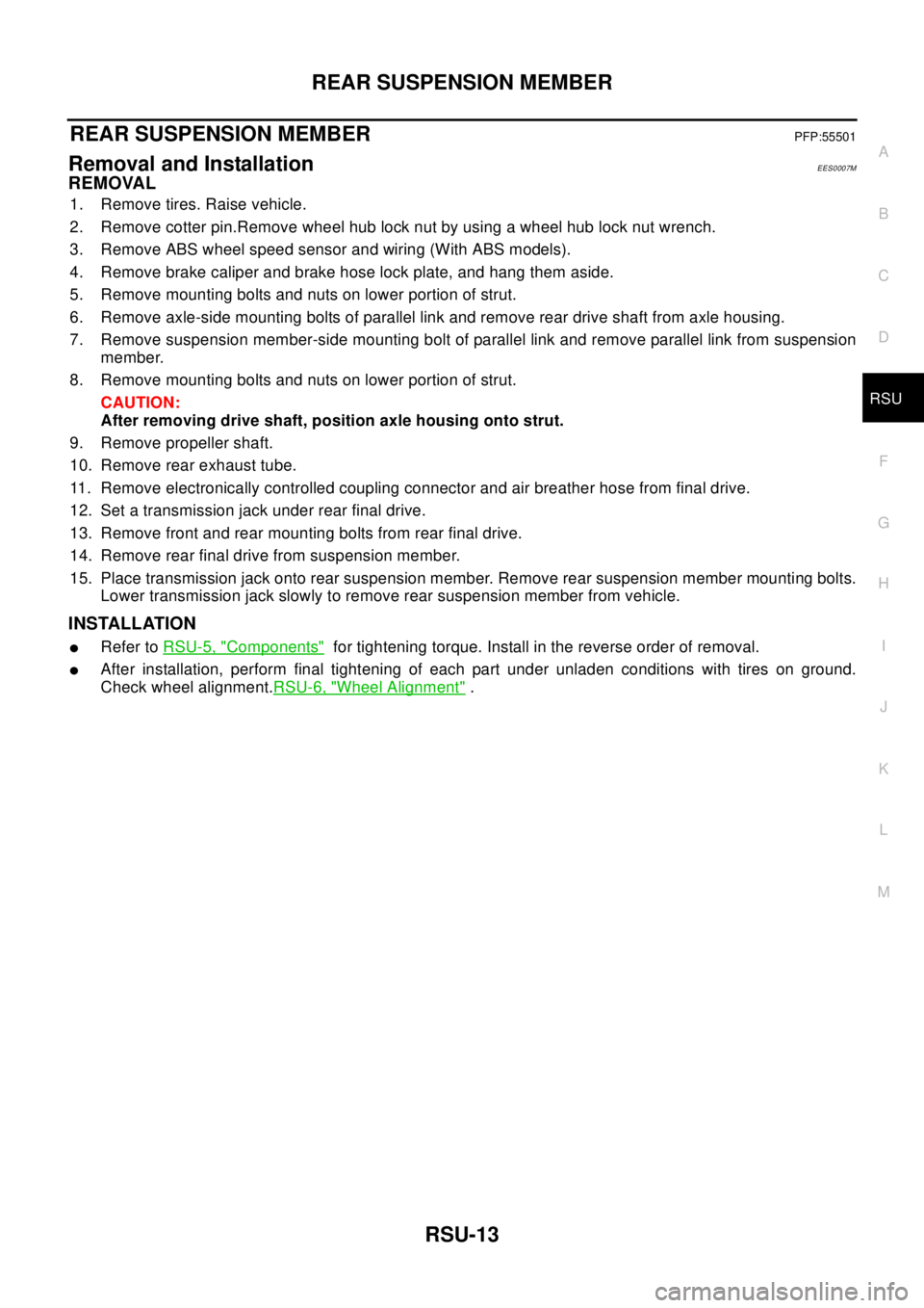
REMOVAL
1. Remove tires. Raise vehicle.
2. Remove cotter pin.Remove wheel hub lock nut by using a wheel hub lock nut wrench.
3. Remove ABS wheel speed sensor and wiring (With ABS models).
4. Remove brake caliper and brake hose lock plate, and hang them aside.
5. Remove mounting bolts and nuts on lower portion of strut.
6. Remove axle-side mounting bolts of parallel link and remove rear drive shaft from axle housing.
7. Remove suspension member-side mounting bolt of parallel link and remove parallel link from suspension
member.
8. Remove mounting bolts and nuts on lower portion of strut.
CAUTION:
After removing drive shaft, position axle housing onto strut.
9. Remove propeller shaft.
10. Remove rear exhaust tube.
11. Remove electronically controlled coupling connector and air breather hose from final drive.
12. Set a transmission jack under rear final drive.
13. Remove front and rear mounting bolts from rear final drive.
14. Remove rear final drive from suspension member.
15. Place transmission jack onto rear suspension member. Remove rear suspension member mounting bolts.
Lower transmission jack slowly to remove rear suspension member from vehicle.
INSTALLATION
lRefer toRSU-5, "Components"for tightening torque. Install in the reverse order of removal.
lAfter installation, perform final tightening of each part under unladen conditions with tires on ground.
Check wheel alignment.RSU-6, "
Wheel Alignment".
Page 2866 of 3066
RSU-14
SERVICE DATA AND SPECIFICATIONS (SDS)
SERVICE DATA AND SPECIFICATIONS (SDS)
PFP:00030
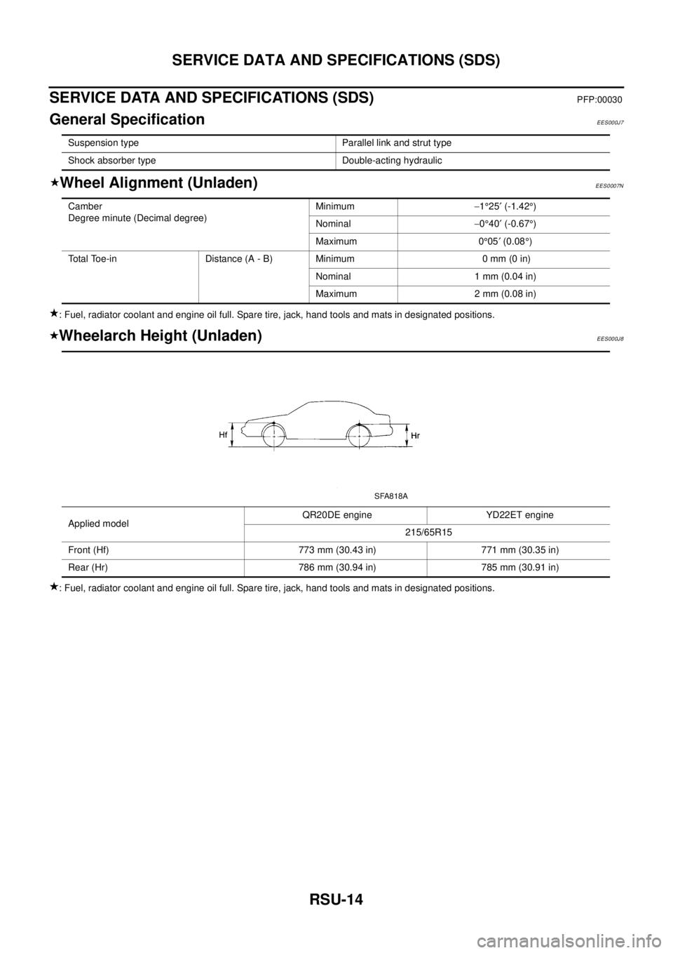
General SpecificationEES000J7
Wheel Alignment (Unladen)EES0007N
: Fuel, radiator coolant and engine oil full. Spare tire, jack, hand tools and mats in designated positions.
Wheelarch Height (Unladen)EES000J8
: Fuel, radiator coolant and engine oil full. Spare tire, jack, hand tools and mats in designated positions.Suspension type Parallel link and strut type
Shock absorber type Double-acting hydraulic
Camber
Degree minute (Decimal degree)Minimum-1°25¢(-1.42°)
Nominal-0°40¢(-0.67°)
Maximum 0°05¢(0.08°)
Total Toe-in Distance (A - B) Minimum 0 mm (0 in)
Nominal 1 mm (0.04 in)
Maximum 2 mm (0.08 in)
Applied modelQR20DE engine YD22ET engine
215/65R15
Front (Hf) 773 mm (30.43 in) 771 mm (30.35 in)
Rear (Hr) 786 mm (30.94 in) 785 mm (30.91 in)
SFA818A
Page 2968 of 3066
SRS-46
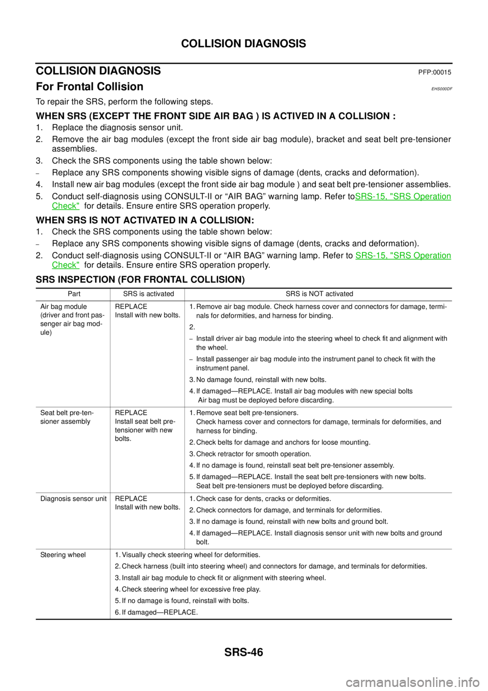
COLLISION DIAGNOSIS
COLLISION DIAGNOSIS
PFP:00015
For Frontal CollisionEHS000DF
To repair the SRS, perform the following steps.
WHEN SRS (EXCEPT THE FRONT SIDE AIR BAG ) IS ACTIVED IN A COLLISION :
1. Replace the diagnosis sensor unit.
2. Remove the air bag modules (except the front side air bag module), bracket and seat belt pre-tensioner
assemblies.
3. Check the SRS components using the table shown below:
–Replace any SRS components showing visible signs of damage (dents, cracks and deformation).
4. Install new air bag modules (except the front side air bag module ) and seat belt pre-tensioner assemblies.
5. Conduct self-diagnosis using CONSULT-II or “AIR BAG” warning lamp. Refer toSRS-15, "
SRS Operation
Check"for details. Ensure entire SRS operation properly.
WHEN SRS IS NOT ACTIVATED IN A COLLISION:
1. Check the SRS components using the table shown below:
–Replace any SRS components showing visible signs of damage (dents, cracks and deformation).
2. Conduct self-diagnosis using CONSULT-II or “AIR BAG” warning lamp. Refer toSRS-15, "
SRS Operation
Check"for details. Ensure entire SRS operation properly.
SRS INSPECTION (FOR FRONTAL COLLISION)
Part SRS is activated SRS is NOT activated
Air bag module
(driver and front pas-
senger air bag mod-
ule)REPLACE
Install with new bolts.1. Remove air bag module. Check harness cover and connectors for damage, termi-
nals for deformities, and harness for binding.
2.
–Install driver air bag module into the steering wheel to check fit and alignment with
the wheel.
–Install passenger air bag module into the instrument panel to check fit with the
instrument panel.
3. No damage found, reinstall with new bolts.
4. If damaged—REPLACE. Install air bag modules with new special bolts
Air bag must be deployed before discarding.
Seat belt pre-ten-
sioner assemblyREPLACE
Install seat belt pre-
tensioner with new
bolts.1. Remove seat belt pre-tensioners.
Check harness cover and connectors for damage, terminals for deformities, and
harness for binding.
2. Check belts for damage and anchors for loose mounting.
3. Check retractor for smooth operation.
4. If no damage is found, reinstall seat belt pre-tensioner assembly.
5. If damaged—REPLACE. Install the seat belt pre-tensioners with new bolts.
Seat belt pre-tensioners must be deployed before discarding.
Diagnosis sensor unit REPLACE
Install with new bolts.1. Check case for dents, cracks or deformities.
2. Check connectors for damage, and terminals for deformities.
3. If no damage is found, reinstall with new bolts and ground bolt.
4. If damaged—REPLACE. Install diagnosis sensor unit with new bolts and ground
bolt.
Steering wheel 1. Visually check steering wheel for deformities.
2. Check harness (built into steering wheel) and connectors for damage, and terminals for deformities.
3. Install air bag module to check fit or alignment with steering wheel.
4. Check steering wheel for excessive free play.
5. If no damage is found, reinstall with bolts.
6. If damaged—REPLACE.