change time NISSAN X-TRAIL 2003 Electronic Manual PDF
[x] Cancel search | Manufacturer: NISSAN, Model Year: 2003, Model line: X-TRAIL, Model: NISSAN X-TRAIL 2003Pages: 3066, PDF Size: 51.47 MB
Page 1917 of 3066
![NISSAN X-TRAIL 2003 Electronic Manual PDF EGR VOLUME CONTROL SYSTEM
EC-803
[YD]
C
D
E
F
G
H
I
J
K
L
MA
EC
EGR VOLUME CONTROL SYSTEMPFP:14710
DescriptionEBS0035N
SYSTEM DESCRIPTION
This system controls flow rate of EGR led from exhaust manifol](/img/5/57402/w960_57402-1916.png "NISSAN X-TRAIL 2003 Electronic Manual PDF EGR VOLUME CONTROL SYSTEM
EC-803
[YD]
C
D
E
F
G
H
I
J
K
L
MA
EC
EGR VOLUME CONTROL SYSTEMPFP:14710
DescriptionEBS0035N
SYSTEM DESCRIPTION
This system controls flow rate of EGR led from exhaust manifol")
EGR VOLUME CONTROL SYSTEM
EC-803
[YD]
C
D
E
F
G
H
I
J
K
L
MA
EC
EGR VOLUME CONTROL SYSTEMPFP:14710
DescriptionEBS0035N
SYSTEM DESCRIPTION
This system controls flow rate of EGR led from exhaust manifold to intake manifold. The opening of the EGR
by-pass passage in the EGR volume control valve changes to control the flow rate. A built-in step motor
moves the valve in steps corresponding to the ECM output pulses. The opening of the valve varies for opti-
mum engine control. The optimum value stored in the ECM is determined by considering various engine con-
ditions.
The EGR volume control valve remains close under the following conditions.
lEngine stopped
lEngine starting
lLow engine coolant temperature
lExcessively high engine coolant temperature
lHigh engine speed
lWide open throttle
COMPONENT DESCRIPTION
EGR Volume Control Valve
The EGR volume control valve uses a step motor to control the flow
rate of EGR from exhaust manifold. This motor has four winding
phases. It operates according to the output pulse signal of the ECM.
Two windings are turned ON and OFF in sequence. Each time an
ON pulse is issued, the valve opens or closes, changing the flow
rate. When no change in the flow rate is needed, the ECM does not
issue the pulse signal. A certain voltage signal is issued so that the
valve remains at that particular opening.
CONSULT-II Reference Value in Data Monitor ModeEBS0035O
Specification data are reference values.
Sensor Input Signal to ECM ECM Function Actuator
Crankshaft position sensor (TDC) Engine speed
EGR volume con-
trolEGR volume control
valve Vehicle speed sensor Vehicle speed
Engine coolant temperature sensor Engine coolant temperature
Ignition switch Start signal
Accelerator pedal position sensor Accelerator pedal position
Mass air flow sensor Amount of intake air
Air conditioner switch Air conditioner operation
SEF908Y
SEF411Y
Page 2010 of 3066
![NISSAN X-TRAIL 2003 Electronic Manual PDF EM-40
[QR20DE]
CAMSHAFT
ValveLifterHoleDiameter
lUsing inside micrometer, measure diameter of valve lifter hole of
cylinder head.
Calculation of Valve Lifter Clearance
(Valve lifter clearance) = (hole](/img/5/57402/w960_57402-2009.png "NISSAN X-TRAIL 2003 Electronic Manual PDF EM-40
[QR20DE]
CAMSHAFT
ValveLifterHoleDiameter
lUsing inside micrometer, measure diameter of valve lifter hole of
cylinder head.
Calculation of Valve Lifter Clearance
(Valve lifter clearance) = (hole")
EM-40
[QR20DE]
CAMSHAFT
ValveLifterHoleDiameter
lUsing inside micrometer, measure diameter of valve lifter hole of
cylinder head.
Calculation of Valve Lifter Clearance
(Valve lifter clearance) = (hole diameter of valve lifter) – (outer diam-
eter of valve lifter).
lWhen out of specified range, referring to each specification of outer and inner diameter, replace either or
both valve lifter and cylinder head.
Valve ClearanceEBS009R1
INSPECTION
lPerform inspection as follows after removal, installation or replacement of camshaft or valve-related parts,
or if there is unusual engine conditions due to changes in valve clearance over time (starting, idling, and/
or noise).
1. Warm up engine. Then stop it.
2. Remove front RH engine side cover.
3. Remove rocker cover.
Refer toEM-31, "
Removal and Installation".
4. Turn crankshaft pulley in normal direction (clockwise when
viewed from front) to align TDC identification notch (without
paint mark) with timing indicator.
5. At this time, check that the both intake and exhaust cam noses
of No. 1 cylinder face outside.
lIf they do not face outside, turn crankshaft pulley once more. Standard:
34.000 - 34.021 mm (1.3386 - 1.3394 in)
Standard:
0.020 - 0.056 mm (0.0008 - 0.0022 in)
PBIC0043E
KBIA0190E
KBIA0400J
Page 2259 of 3066
GI-6
PRECAUTIONS
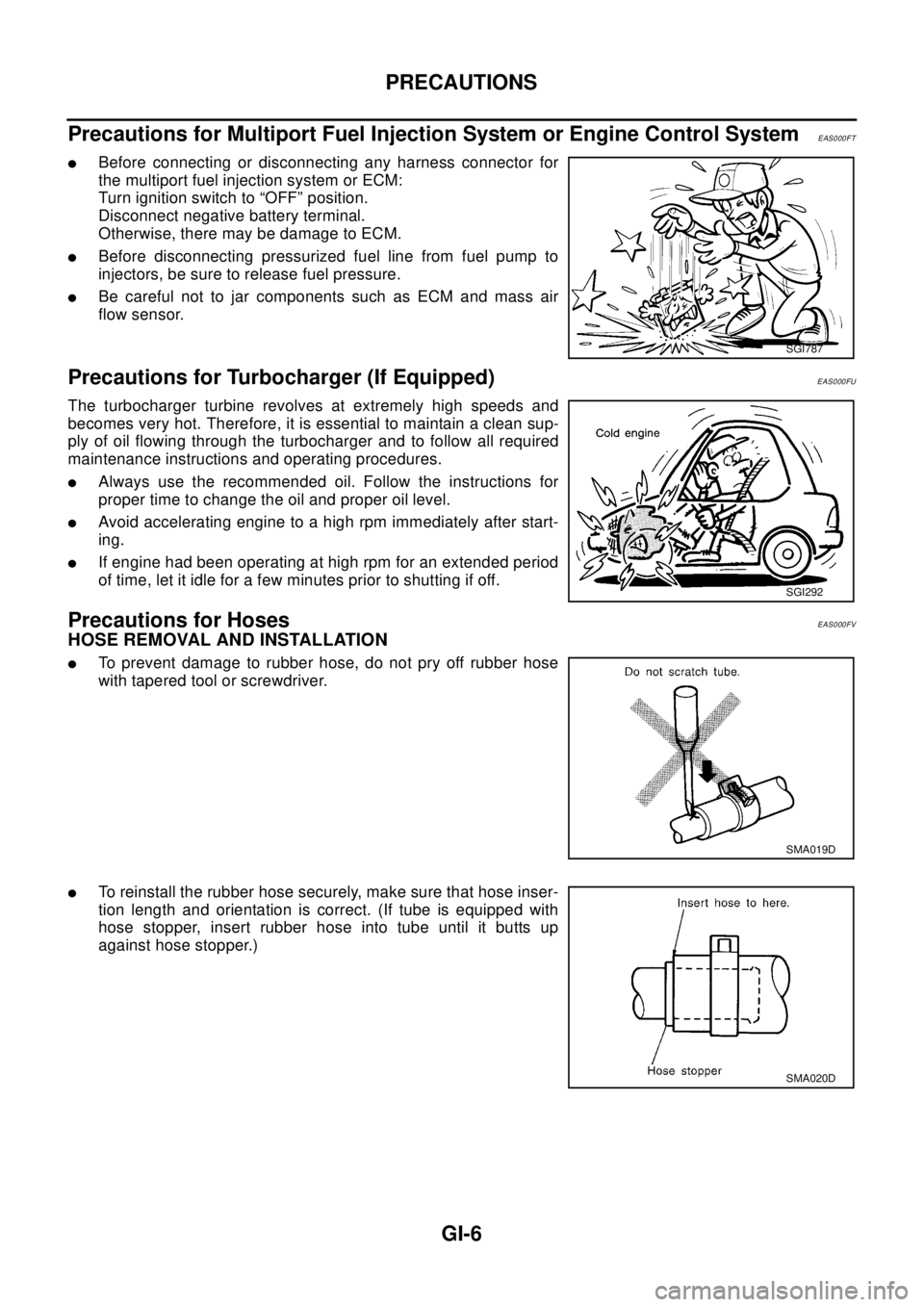
Precautions for Multiport Fuel Injection System or Engine Control System
EAS000FT
lBefore connecting or disconnecting any harness connector for
the multiport fuel injection system or ECM:
Turn ignition switch to “OFF” position.
Disconnect negative battery terminal.
Otherwise, there may be damage to ECM.
lBefore disconnecting pressurized fuel line from fuel pump to
injectors, be sure to release fuel pressure.
lBe careful not to jar components such as ECM and mass air
flow sensor.
Precautions for Turbocharger (If Equipped)EAS000FU
The turbocharger turbine revolves at extremely high speeds and
becomes very hot. Therefore, it is essential to maintain a clean sup-
ply of oil flowing through the turbocharger and to follow all required
maintenance instructions and operating procedures.
lAlways use the recommended oil. Follow the instructions for
proper time to change the oil and proper oil level.
lAvoid accelerating engine to a high rpm immediately after start-
ing.
lIf engine had been operating at high rpm for an extended period
of time, let it idle for a few minutes prior to shutting if off.
Precautions for HosesEAS000FV
HOSE REMOVAL AND INSTALLATION
lTo prevent damage to rubber hose, do not pry off rubber hose
with tapered tool or screwdriver.
lTo reinstall the rubber hose securely, make sure that hose inser-
tion length and orientation is correct. (If tube is equipped with
hose stopper, insert rubber hose into tube until it butts up
against hose stopper.)
SGI787
SGI292
SMA019D
SMA020D
Page 2280 of 3066
SERVICE INFORMATION FOR ELECTRICAL INCIDENT
GI-27
Cold or Hot Start Up
On some occasions an electrical incident may occur only when the car is started cold, or it may occur when
the car is restarted hot shortly after being turned off. In these cases you may have to keep the car overnight to
make a proper diagnosis.
CIRCUIT INSPECTION
Introduction
In general, testing electrical circuits is an easy task if it is approached in a logical and organized method.
Before beginning it is important to have all available information on the system to be tested. Also, get a thor-
ough understanding of system operation. Then you will be able to use the appropriate equipment and follow
the correct test procedure.
You may have to simulate vehicle vibrations while testing electrical components. Gently shake the wiring har-
ness or electrical component to do this.
NOTE:
Refer to "How to Check Terminal” to probe or check terminal.
Testing for “Opens” in the Circuit
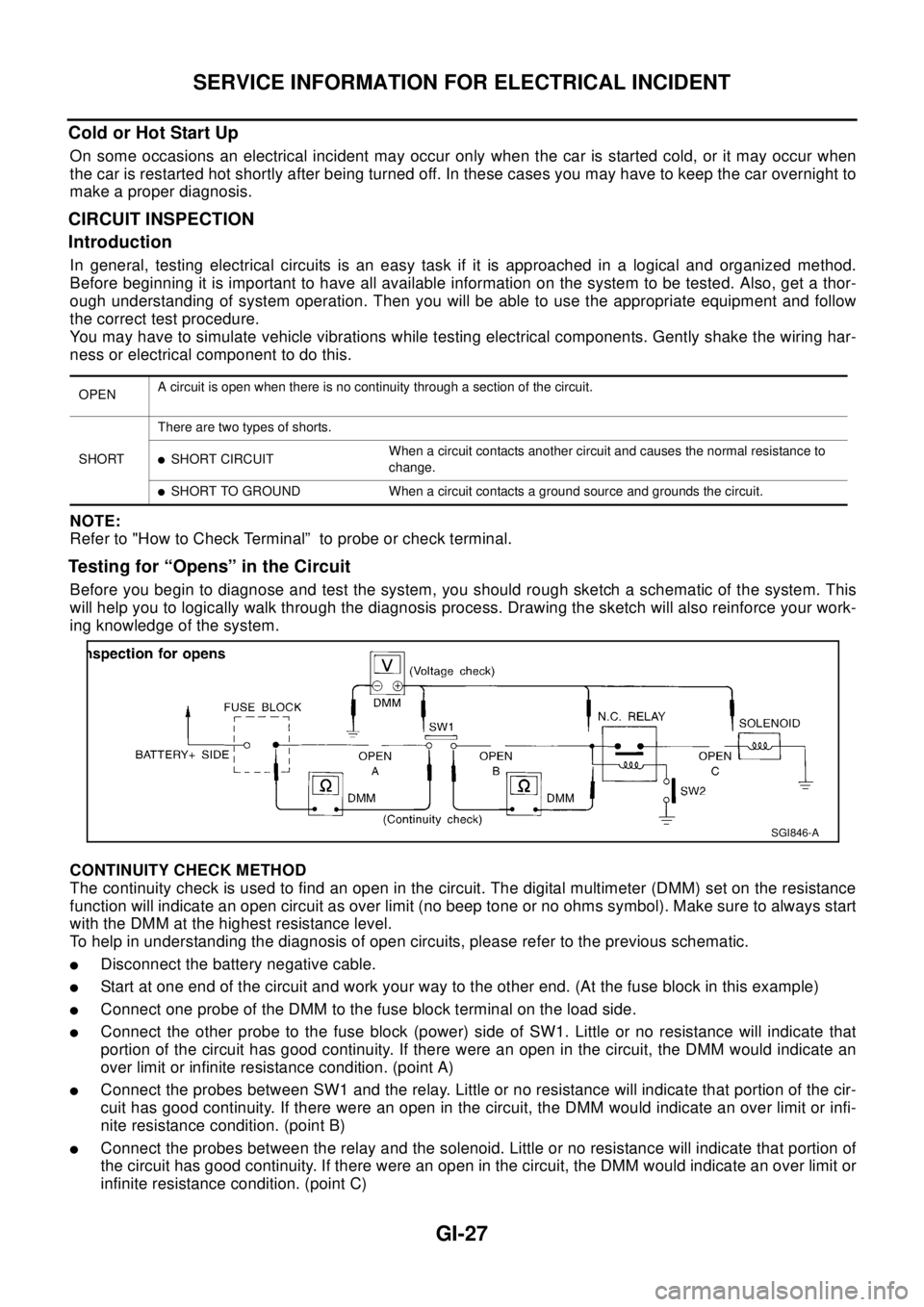
Before you begin to diagnose and test the system, you should rough sketch a schematic of the system. This
will help you to logically walk through the diagnosis process. Drawing the sketch will also reinforce your work-
ing knowledge of the system.
CONTINUITY CHECK METHOD
The continuity check is used to find an open in the circuit. The digital multimeter (DMM) set on the resistance
function will indicate an open circuit as over limit (no beep tone or no ohms symbol). Make sure to always start
with the DMM at the highest resistance level.
To help in understanding the diagnosis of open circuits, please refer to the previous schematic.
lDisconnect the battery negative cable.
lStart at one end of the circuit and work your way to the other end. (At the fuse block in this example)
lConnect one probe of the DMM to the fuse block terminal on the load side.
lConnect the other probe to the fuse block (power) side of SW1. Little or no resistance will indicate that
portion of the circuit has good continuity. If there were an open in the circuit, the DMM would indicate an
over limit or infinite resistance condition. (point A)
lConnect the probes between SW1 and the relay. Little or no resistance will indicate that portion of the cir-
cuit has good continuity. If there were an open in the circuit, the DMM would indicate an over limit or infi-
nite resistance condition. (point B)
lConnect the probes between the relay and the solenoid. Little or no resistance will indicate that portion of
the circuit has good continuity. If there were an open in the circuit, the DMM would indicate an over limit or
infinite resistance condition. (point C)
OPENA circuit is open when there is no continuity through a section of the circuit.
SHORTThere are two types of shorts.
lSHORT CIRCUITWhen a circuit contacts another circuit and causes the normal resistance to
change.
lSHORT TO GROUND When a circuit contacts a ground source and grounds the circuit.
SGI846-A
Page 2290 of 3066
LIFTING POINT
GI-37
LIFTING POINTPFP:00000
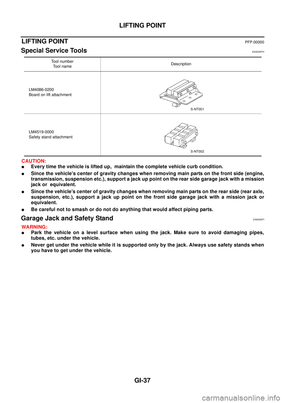
Special Service ToolsEAS000FH
CAUTION:
lEvery time the vehicle is lifted up, maintain the complete vehicle curb condition.
lSince the vehicle's center of gravity changes when removing main parts on the front side (engine,
transmission, suspension etc.), support a jack up point on the rear side garage jack with a mission
jack or equivalent.
lSince the vehicle's center of gravity changes when removing main parts on the rear side (rear axle,
suspension, etc.), support a jack up point on the front side garage jack with a mission jack or
equivalent.
lBe careful not to smash or do not do anything that would affect piping parts.
Garage Jack and Safety StandEAS000FI
WA RN ING:
lPark the vehicle on a level surface when using the jack. Make sure to avoid damaging pipes,
tubes, etc. under the vehicle.
lNever get under the vehicle while it is supported only by the jack. Always use safety stands when
you have to get under the vehicle.
Tool number
To o l n a m eDescription
LM4086-0200
Board on lift attachment
LM4519-0000
Safety stand attachment
S-NT001
S-NT002
Page 2443 of 3066
![NISSAN X-TRAIL 2003 Electronic Manual PDF ILLUMINATION
LT-45
C
D
E
F
G
H
I
J
L
MA
B
LT
ILLUMINATIONPFP:27545
System DescriptionEKS003C7
Power is supplied at all times
lthrough 10A fuse [No. 31, located in the fuse and fusible link box]
lto li](/img/5/57402/w960_57402-2442.png "NISSAN X-TRAIL 2003 Electronic Manual PDF ILLUMINATION
LT-45
C
D
E
F
G
H
I
J
L
MA
B
LT
ILLUMINATIONPFP:27545
System DescriptionEKS003C7
Power is supplied at all times
lthrough 10A fuse [No. 31, located in the fuse and fusible link box]
lto li")
ILLUMINATION
LT-45
C
D
E
F
G
H
I
J
L
MA
B
LT
ILLUMINATIONPFP:27545
System DescriptionEKS003C7
Power is supplied at all times
lthrough 10A fuse [No. 31, located in the fuse and fusible link box]
lto lighting switch terminal 11.
The lighting switch must be in the 1ST or 2ND position for illumination.
The following chart shows the power and ground connector terminals for the components included in the illu-
mination system.
Component Connector No. Power terminal Ground terminal
Headlamp washier switch M23 3 4
Headlamp aiming switch M24 3 4
Door mirror remote control
switchM26 10 1
VDC off switch M25 3 4
Hazard switch M51 7 8
4WD mode switch M39 4 3
Rear window defogger switch M50 5 6
A/C auto amp. M52 12 11
Combination meter
(LHD models)M46 56 66
Combination meter
(RHD models)M46 45 56
Audio M42 2 1
CD auto changer M82 34 35
Heater control panel M55 2 6
A/T device M58 3 4
Cigarette lighter M56 3 2
Heated seat switch LH
(LHD models)B131 5 6
Heated seat switch RH
(LHD models)B132 5 6
Heated seat switch LH
(RHD models)B35 5 6
Heated seat switch RH
(RHD models)B34 5 6
Page 2474 of 3066
![NISSAN X-TRAIL 2003 Electronic Manual PDF LU-8
[QR20DE]
ENGINE OIL
Changing Engine Oil
EBS009SV
WAR NIN G:
lBe careful not to burn yourself, as the engine oil is hot.
lProlonged and repeated contact with used engine oil may
cause skin cancer:](/img/5/57402/w960_57402-2473.png "NISSAN X-TRAIL 2003 Electronic Manual PDF LU-8
[QR20DE]
ENGINE OIL
Changing Engine Oil
EBS009SV
WAR NIN G:
lBe careful not to burn yourself, as the engine oil is hot.
lProlonged and repeated contact with used engine oil may
cause skin cancer:")
LU-8
[QR20DE]
ENGINE OIL
Changing Engine Oil
EBS009SV
WAR NIN G:
lBe careful not to burn yourself, as the engine oil is hot.
lProlonged and repeated contact with used engine oil may
cause skin cancer: try to avoid direct skin contact with
used oil. If skin contact is made, wash thoroughly with soap
or hand cleaner as soon as possible.
1. Warm up engine, and check for oil leakage from engine compo-
nents.
2. Stop engine and wait for 10 minutes.
3. Remove drain plug and oil filler cap.
4. Drain oil and refill with new engine oil.
Oil specification and viscosity:
lAPI grade SG, SH or SJ.
lILSAC grade GF-I or GF-II
lRefer toMA-17, "RECOMMENDED FLUIDS AND LUBRICANTS".
Oil capacity (Approximate):
CAUTION:
lBe sure to clean drain plug and install with new washer.
lThe refill capacity depends on the oil temperature and drain time. Use these specifications for ref-
erence only.
Always use the dipstick to the determine when the proper amount of oil is in the engine.
5. Warm up engine and check area around drain plug and oil filter for oil leakage.
6. Stop engine and wait for 10 minutes.
7. Check oil level.
Drain and refillWith oil filter change
3.9 (3-3/8 Imp qt)
Without oil filter change
3.5 (3-1/8 Imp qt)
Dry engine (engine overhaul)
4.5 (4 Imp qt)
Oil pan drain plug:
: 29.4 - 39.2 N·m (3.0 - 4.0 kg-m, 22 - 28 ft-lb)
PBIC0250E
Page 2485 of 3066
![NISSAN X-TRAIL 2003 Electronic Manual PDF ENGINE OIL
LU-19
[YD22DDTi]
C
D
E
F
G
H
I
J
K
L
MA
LUChanging Engine OilEBS00B04
WA RN ING:
lBe careful not to burn yourself, as the engine oil is hot.
lProlonged and repeated contact with used engine](/img/5/57402/w960_57402-2484.png "NISSAN X-TRAIL 2003 Electronic Manual PDF ENGINE OIL
LU-19
[YD22DDTi]
C
D
E
F
G
H
I
J
K
L
MA
LUChanging Engine OilEBS00B04
WA RN ING:
lBe careful not to burn yourself, as the engine oil is hot.
lProlonged and repeated contact with used engine")
ENGINE OIL
LU-19
[YD22DDTi]
C
D
E
F
G
H
I
J
K
L
MA
LUChanging Engine OilEBS00B04
WA RN ING:
lBe careful not to burn yourself, as the engine oil is hot.
lProlonged and repeated contact with used engine oil may
cause skin cancer: try to avoid direct skin contact with
used oil. If skin contact is made, wash thoroughly with soap
or hand cleaner as soon as possible.
1. Warm up engine, and check for oil leakage from engine compo-
nents.
2. Stop engine and wait for 10 minutes.
3. Remove drain plug and oil filler cap.
4. Drain oil and refill with new engine oil.
Oil specification and viscosity:
lAPI grade CF-4.
lRefer toMA-17, "RECOMMENDED FLUIDS AND LUBRI-
CANTS".
Oil capcity (Approximate):
lThe refill capacity depends on the oil temperature and drain time. Use these specifications for reference
only.
Always use the dipstick to the determine when the proper amount of oil is in the engine.
CAUTION:
lBe sure to clean drain plug and install with new washer.
lThe refill capacity depends on the oil temperature and drain time. Use these specifications for ref-
erence only.
Always use the dipstick to the determine when the proper amount of oil is in the engine.
5. Warm up engine and check area around drain plug and oil filter for oil leakage.
6. Stop engine and wait for 10 minutes.
7. Check oil level.Oil pressure switch:
: 12.3 - 17.2 N·m (1.3 - 1.7 kg-m, 9 - 12 ft-lb)
PBIC0527E
Drain and refillWith oil filter change
5.2 (4-5/8 Imp qt)
Without oil filter change
4.9 (4-3/8 Imp qt)
Dry engine (engine overhaul)6.3 (5-1/2 Imp qt)
Oil pan drain plug:
:29-39N·m(3.0-4.0kg-m,22-29ft-lb)
SBIA0122E
Page 2498 of 3066

MA-6
GENERAL MAINTENANCE
GENERAL MAINTENANCE
PFP:00000
General MaintenanceELS000AL
General maintenance includes those items which should be checked during the normal day-to-day operation
of the vehicle. They are essential if the vehicle is to continue operating properly. The owners can perform the
checks and inspections themselves or they can have their NISSAN dealers do them for a nominal charge.
OUTSIDE THE VEHICLE
The maintenance items listed here should be performed from time to time, unless otherwise specified.
INSIDE THE VEHICLE
The maintenance items listed here should be checked on a regular basis, such as when performing periodic maintenance, cleaning the
vehicle, etc.
UNDER THE HOOD AND VEHICLE
The maintenance items listed here should be checked periodically e.g. each time you check the engine oil or refuel.Item Reference page
TiresCheck the pressure with a gauge periodically when at a service station, includ-
ing the spare, and adjust to the specified pressure if necessary. Check carefully
for damage, cuts or excessive wear.—
Windshield wiper
bladesCheck for cracks or wear if not functioning correctly. —
Doors and engine
hoodCheck that all doors, the engine hood, the trunk lid and back door operate prop-
erly. Also ensure that all latches lock securely. Lubricate if necessary. Make sure
that the secondary latch keeps the hood from opening when the primary latch is
released.
When driving in areas using road salt or other corrosive materials, check for
lubrication frequently.BL-4
,BL-8
Tire rotationTires should be rotated every 5,000 km (3,000 miles).MA-38
Item Reference page
LampsMake sure that the headlamps, stop lamps, tail lamps, turn signal lamps, and
other lamps are all operating properly and installed securely. Also check head-
lamp aim.—
Warning lamps and
chimesMake sure that all warning lamps and buzzers/chimes are operating properly. —
Steering wheelCheck that it has the specified play.
Check for changes in the steering conditions, such as excessive free play, hard
steering or strange noises.
Free play: Less than 35 mm (1.38 in)—
Seat beltsCheck that all parts of the seat belt system (e.g. buckles, anchors, adjusters and
retractors) operate properly and smoothly, and are installed securely. Check the
belt webbing for cuts, fraying, wear or damage.SB-3
Item Reference page
Windshield washer
fluidCheck that there is adequate fluid in the tank. —
Engine coolant levelCheck the coolant level when the engine is cold.CO-9
(QR20DE)
CO-30
(YD22DDTi)
Engine oil levelCheck the level after parking the vehicle (on level ground) and turning off the
engine.LU-7
(QR20DE)
LU-18
(YD22DDTi)
Brake and clutch fluid
levelsMake sure that the brake and clutch fluid levels are between the “MAX” and
“MIN” lines on the reservoir.MA-35
,MA-38
BatteryCheck the fluid level in each cell. It should be between the “MAX” and “MIN”
lines.—
Page 2516 of 3066
MA-24
ENGINE MAINTENANCE (QR20DE)
Changing Engine Oil
ELS000AS
WAR NIN G:
lBe careful not to burn yourself, as the engine oil is hot.
lProlonged and repeated contact with used engine oil may
cause skin cancer; try to avoid direct skin contact with
used oil. If skin contact is made, wash thoroughly with soap
or hand cleaner as soon as possible.
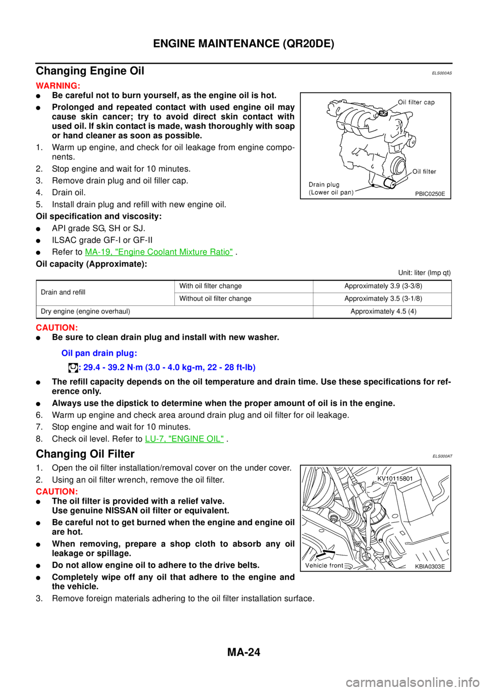
1. Warm up engine, and check for oil leakage from engine compo-
nents.
2. Stop engine and wait for 10 minutes.
3. Remove drain plug and oil filler cap.
4. Drain oil.
5. Install drain plug and refill with new engine oil.
Oil specification and viscosity:
lAPI grade SG, SH or SJ.
lILSAC grade GF-I or GF-II
lRefer toMA-19, "Engine Coolant Mixture Ratio".
Oil capacity (Approximate):
Unit: liter (lmp qt)
CAUTION:
lBe sure to clean drain plug and install with new washer.
lThe refill capacity depends on the oil temperature and drain time. Use these specifications for ref-
erence only.
lAlways use the dipstick to determine when the proper amount of oil is in the engine.
6. Warm up engine and check area around drain plug and oil filter for oil leakage.
7. Stop engine and wait for 10 minutes.
8. Check oil level. Refer toLU-7, "
ENGINE OIL".
Changing Oil FilterELS000AT
1. Open the oil filter installation/removal cover on the under cover.
2. Using an oil filter wrench, remove the oil filter.
CAUTION:
lThe oil filter is provided with a relief valve.
Use genuine NISSAN oil filter or equivalent.
lBe careful not to get burned when the engine and engine oil
are hot.
lWhen removing, prepare a shop cloth to absorb any oil
leakage or spillage.
lDo not allow engine oil to adhere to the drive belts.
lCompletely wipe off any oil that adhere to the engine and
the vehicle.
3. Remove foreign materials adhering to the oil filter installation surface.
PBIC0250E
Drain and refillWith oil filter change Approximately 3.9 (3-3/8)
Without oil filter change Approximately 3.5 (3-1/8)
Dry engine (engine overhaul) Approximately 4.5 (4)
Oil pan drain plug:
: 29.4 - 39.2 N·m (3.0 - 4.0 kg-m, 22 - 28 ft-lb)
KBIA0303E