door lock NISSAN X-TRAIL 2003 Electronic Manual PDF
[x] Cancel search | Manufacturer: NISSAN, Model Year: 2003, Model line: X-TRAIL, Model: NISSAN X-TRAIL 2003Pages: 3066, PDF Size: 51.47 MB
Page 2454 of 3066

LT-56
INTERIOR ROOM LAMP
lunlock signal is supplied from driver's door unlock sensor while all doors are closed and key is out of igni-
tion key cylinder
lkey is removed from ignition key cylinder while all doors are closed
ldriver's door is opened and then closed while key is out of the iginition key cylinder. (However, if the
driver's door is closed with the key inserted in the ignition key cylinder after the driver's door is opened
with the key removed, the timer is operated.)
The timer is canceled when:
ldriver's door is locked,
ldriver's door is opened, or
lignition switch is turned ON.
ON-OFF CONTROL
When the driver side door, front passenger door, rear LH or RH door is opened, the interior room lamp turns
on while the interior room lamp switch is in the “DOOR” position.
Page 2457 of 3066
INTERIOR ROOM LAMP
LT-59
C
D
E
F
G
H
I
J
L
MA
B
LT
Interior Room Lamp Timer Does Not OperateEKS003BT
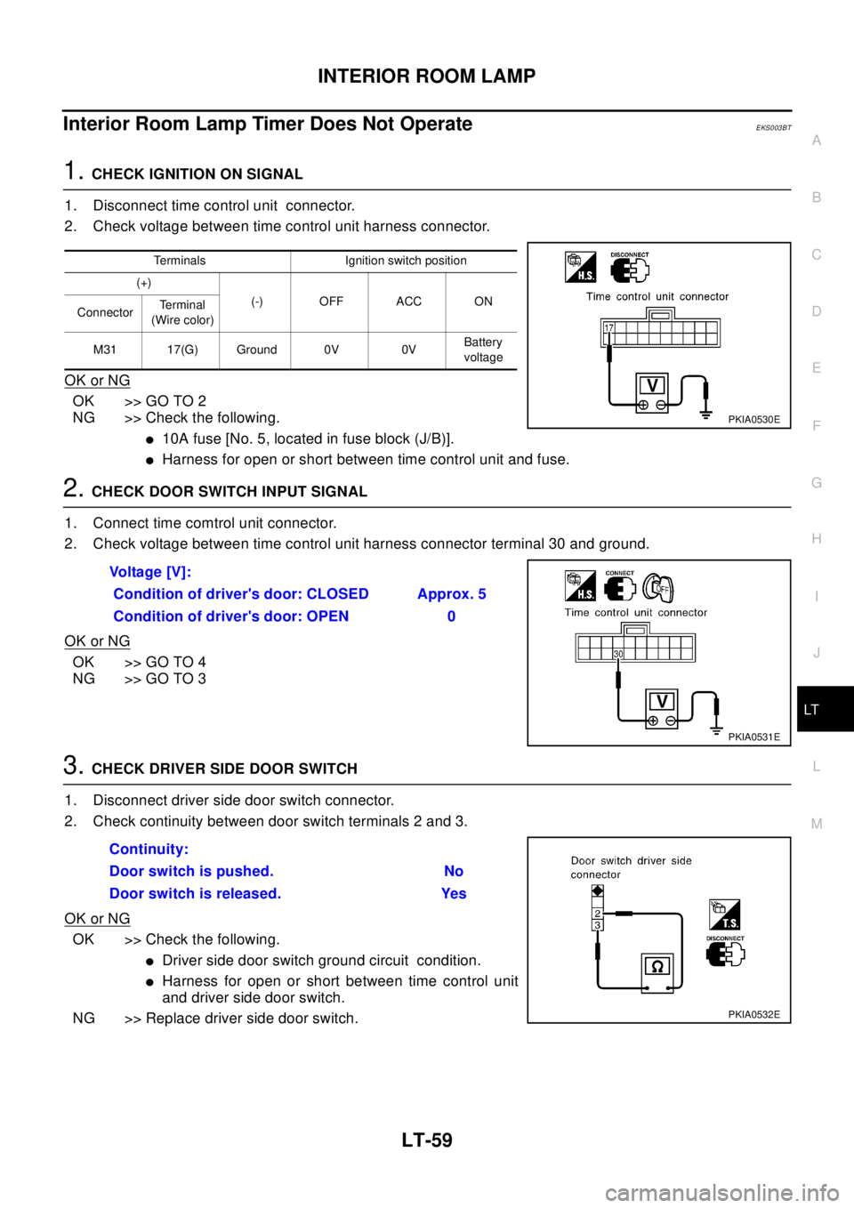
1.CHECK IGNITION ON SIGNAL
1. Disconnect time control unit connector.
2. Check voltage between time control unit harness connector.
OK or NG
OK >> GO TO 2
NG >> Check the following.
l10A fuse [No. 5, located in fuse block (J/B)].
lHarness for open or short between time control unit and fuse.
2.CHECK DOOR SWITCH INPUT SIGNAL
1. Connect time comtrol unit connector.
2. Check voltage between time control unit harness connector terminal 30 and ground.
OK or NG
OK >> GO TO 4
NG >> GO TO 3
3.CHECK DRIVER SIDE DOOR SWITCH
1. Disconnect driver side door switch connector.
2. Check continuity between door switch terminals 2 and 3.
OK or NG
OK >> Check the following.
lDriver side door switch ground circuit condition.
lHarness for open or short between time control unit
and driver side door switch.
NG >> Replace driver side door switch.
Terminals Ignition switch position
(+)
(-) OFF ACC ON
ConnectorTe r m i n a l
(Wire color)
M31 17(G) Ground 0V 0VBattery
voltage
PKIA0530E
Vo l ta g e [ V ] :
Condition of driver's door: CLOSED Approx. 5
Condition of driver's door: OPEN 0
PKIA0531E
Continuity:
Door switch is pushed. No
Door switch is released. Yes
PKIA0532E
Page 2458 of 3066
LT-60
INTERIOR ROOM LAMP
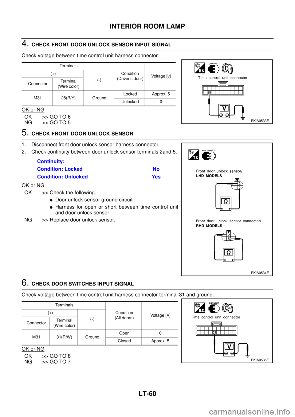
4.CHECK FRONT DOOR UNLOCK SENSOR INPUT SIGNAL
Check voltage between time control unit harness connector.
OK or NG
OK >> GO TO 6
NG >> GO TO 5
5.CHECK FRONT DOOR UNLOCK SENSOR
1. Disconnect front door unlock sensor harness connector.
2. Check continuity between door unlock sensor terminals 2and 5.
OK or NG
OK >> Check the following.
lDoor unlock sensor ground circuit
lHarness for open or short between time control unit
and door unlock sensor
NG >> Replace door unlock sensor.
6.CHECK DOOR SWITCHES INPUT SIGNAL
Check voltage between time control unit harness connector terminal 31 and ground.
OK or NG
OK >> GO TO 8
NG >> GO TO 7
Te r m i n a l s
Condition
(Driver's door)Voltage [v] (+)
(-)
ConnectorTe r m i n a l
(Wire color)
M31 28(R/Y) GroundLocked Approx. 5
Unlocked 0
PKIA0533E
Continuity:
Condition: Locked No
Condition: Unlocked Yes
PKIA0534E
Te r m i n a l s
Condition
(All doors)Voltage [V] (+)
(-)
ConnectorTerminal
(Wire color)
M31 31(R/W) GroundOpen 0
Closed Approx. 5
PKIA0535E
Page 2459 of 3066
INTERIOR ROOM LAMP
LT-61
C
D
E
F
G
H
I
J
L
MA
B
LT
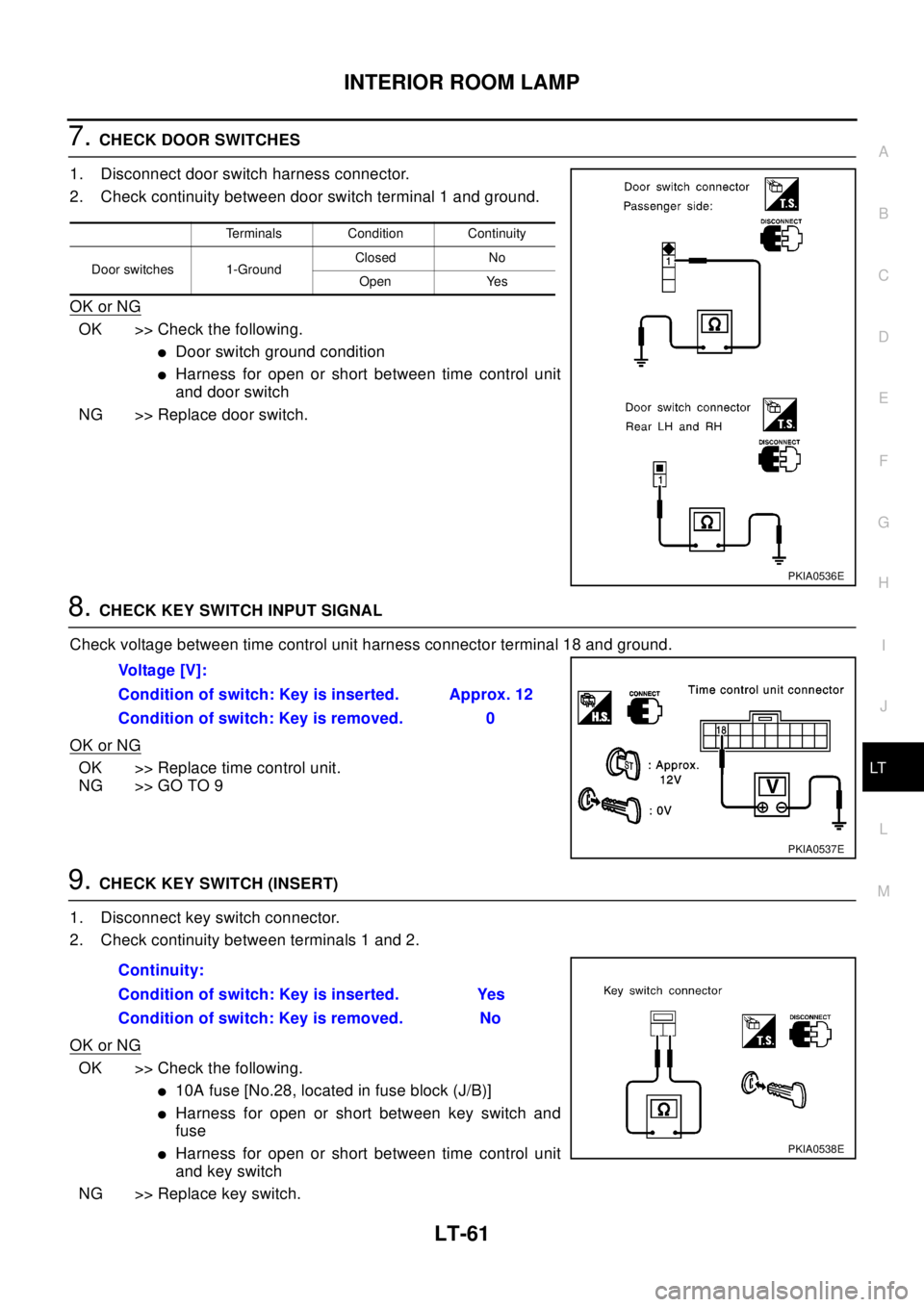
7.CHECK DOOR SWITCHES
1. Disconnect door switch harness connector.
2. Check continuity between door switch terminal 1 and ground.
OK or NG
OK >> Check the following.
lDoor switch ground condition
lHarness for open or short between time control unit
and door switch
NG >> Replace door switch.
8.CHECK KEY SWITCH INPUT SIGNAL
Check voltage between time control unit harness connector terminal 18 and ground.
OK or NG
OK >> Replace time control unit.
NG >> GO TO 9
9.CHECK KEY SWITCH (INSERT)
1. Disconnect key switch connector.
2. Check continuity between terminals 1 and 2.
OK or NG
OK >> Check the following.
l10A fuse [No.28, located in fuse block (J/B)]
lHarness for open or short between key switch and
fuse
lHarness for open or short between time control unit
and key switch
NG >> Replace key switch.
Terminals Condition Continuity
Door switches 1-GroundClosed No
Open Yes
PKIA0536E
Vo l ta g e [ V ] :
Condition of switch: Key is inserted. Approx. 12
Condition of switch: Key is removed. 0
PKIA0537E
Continuity:
Condition of switch: Key is inserted. Yes
Condition of switch: Key is removed. No
PKIA0538E
Page 2460 of 3066
LT-62
INTERIOR ROOM LAMP
Interior Room Lamp Timer Does Not Cancel
EKS003BU
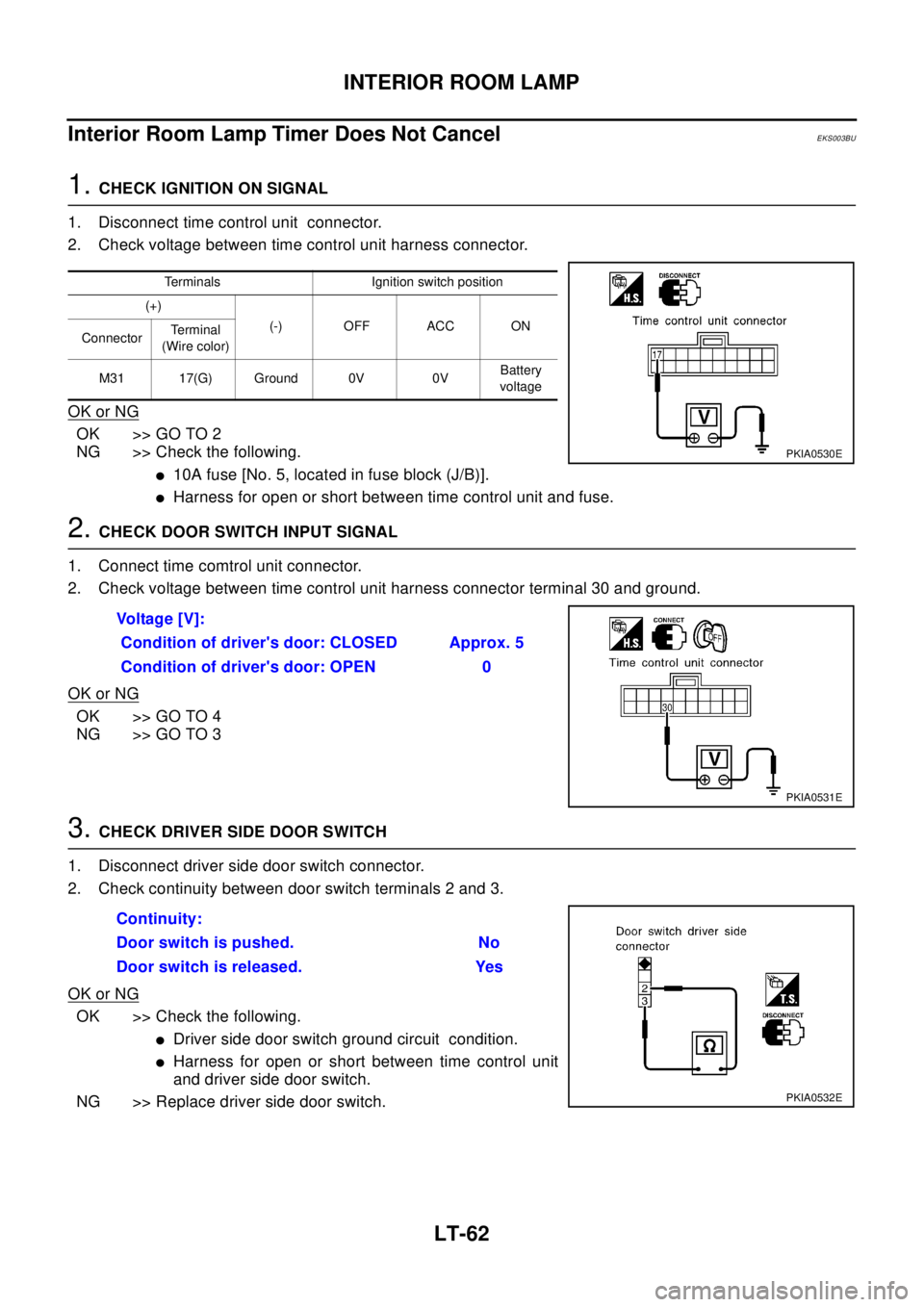
1.CHECK IGNITION ON SIGNAL
1. Disconnect time control unit connector.
2. Check voltage between time control unit harness connector.
OK or NG
OK >> GO TO 2
NG >> Check the following.
l10A fuse [No. 5, located in fuse block (J/B)].
lHarness for open or short between time control unit and fuse.
2.CHECK DOOR SWITCH INPUT SIGNAL
1. Connect time comtrol unit connector.
2. Check voltage between time control unit harness connector terminal 30 and ground.
OK or NG
OK >> GO TO 4
NG >> GO TO 3
3.CHECK DRIVER SIDE DOOR SWITCH
1. Disconnect driver side door switch connector.
2. Check continuity between door switch terminals 2 and 3.
OK or NG
OK >> Check the following.
lDriver side door switch ground circuit condition.
lHarness for open or short between time control unit
and driver side door switch.
NG >> Replace driver side door switch.
Terminals Ignition switch position
(+)
(-) OFF ACC ON
ConnectorTe r m i n a l
(Wire color)
M31 17(G) Ground 0V 0VBattery
voltage
PKIA0530E
Vo l ta g e [ V ] :
Condition of driver's door: CLOSED Approx. 5
Condition of driver's door: OPEN 0
PKIA0531E
Continuity:
Door switch is pushed. No
Door switch is released. Yes
PKIA0532E
Page 2461 of 3066
INTERIOR ROOM LAMP
LT-63
C
D
E
F
G
H
I
J
L
MA
B
LT
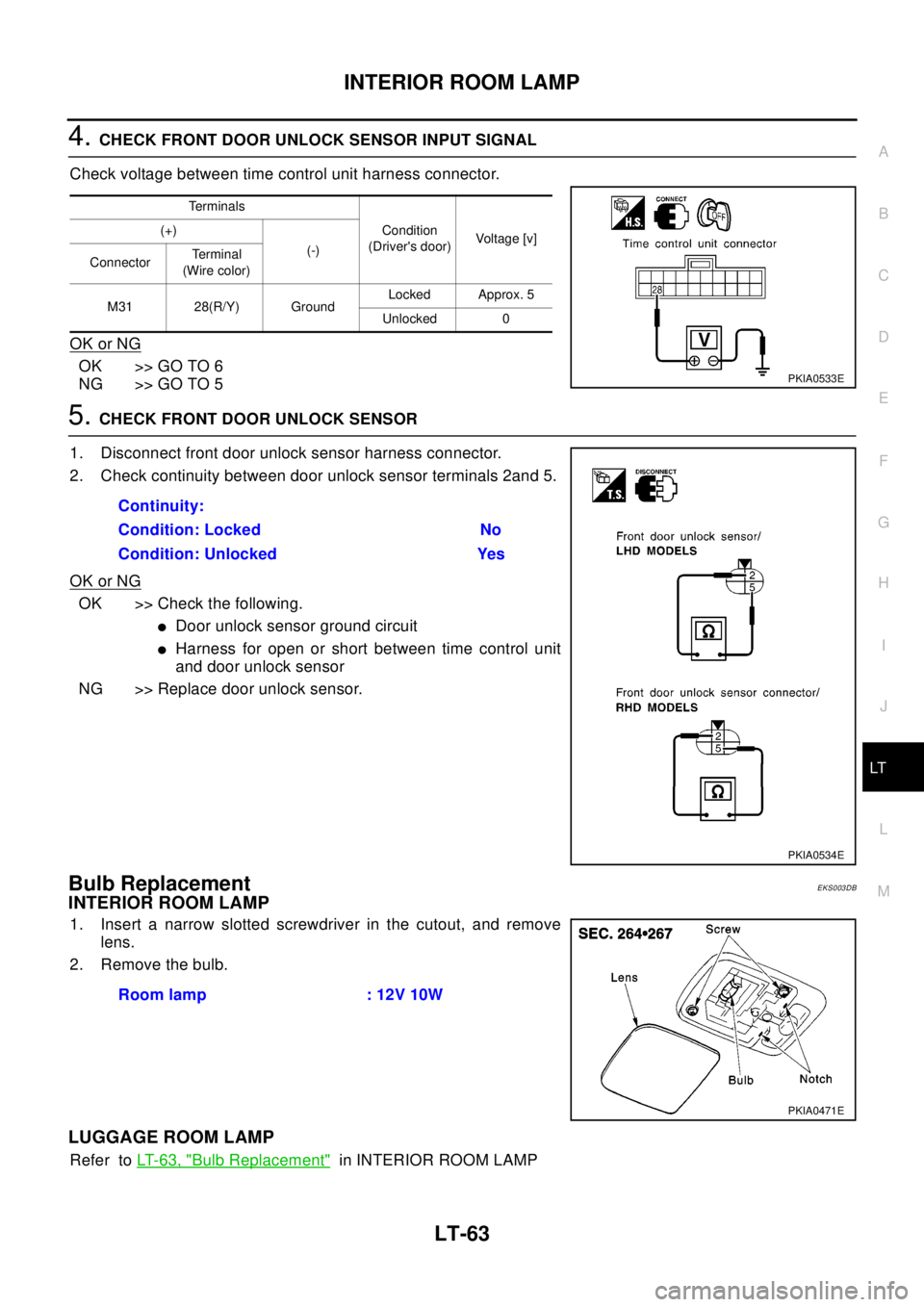
4.CHECK FRONT DOOR UNLOCK SENSOR INPUT SIGNAL
Check voltage between time control unit harness connector.
OK or NG
OK >> GO TO 6
NG >> GO TO 5
5.CHECK FRONT DOOR UNLOCK SENSOR
1. Disconnect front door unlock sensor harness connector.
2. Check continuity between door unlock sensor terminals 2and 5.
OK or NG
OK >> Check the following.
lDoor unlock sensor ground circuit
lHarness for open or short between time control unit
and door unlock sensor
NG >> Replace door unlock sensor.
Bulb ReplacementEKS003DB
INTERIOR ROOM LAMP
1. Insert a narrow slotted screwdriver in the cutout, and remove
lens.
2. Remove the bulb.
LUGGAGE ROOM LAMP
Refer toLT-63, "Bulb Replacement"in INTERIOR ROOM LAMP
Terminals
Condition
(Driver's door)Voltag e [v ] (+)
(-)
ConnectorTerminal
(Wire color)
M31 28(R/Y) GroundLocked Approx. 5
Unlocked 0
PKIA0533E
Continuity:
Condition: Locked No
Condition: Unlocked Yes
PKIA0534E
Room lamp : 12V 10W
PKIA0471E
Page 2496 of 3066
MA-4
DESCRIPTION
DESCRIPTION
PFP:00000
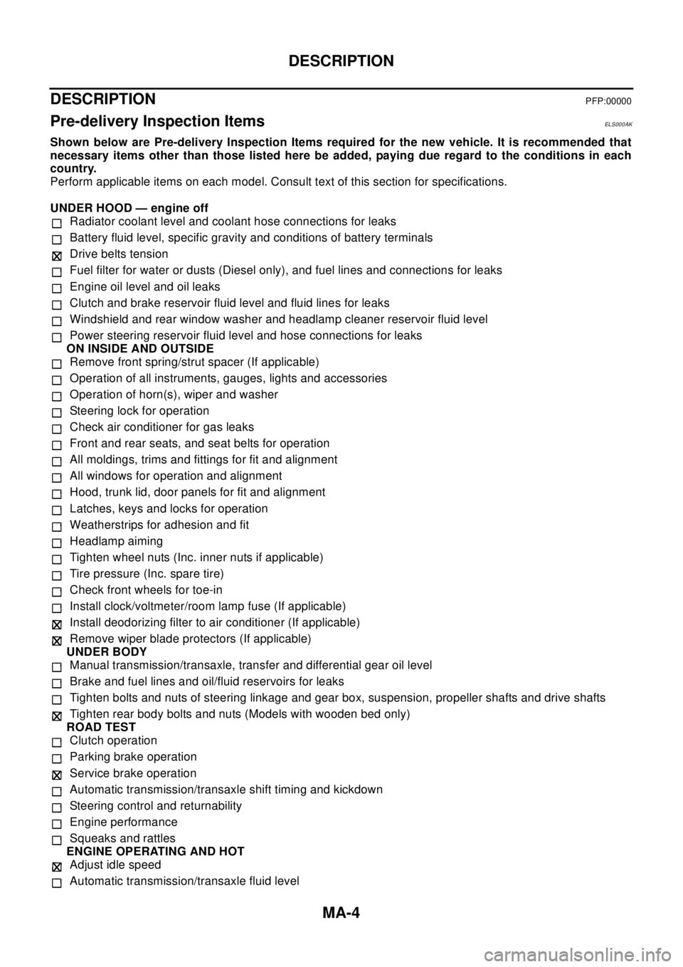
Pre-delivery Inspection ItemsELS000AK
Shown below are Pre-delivery Inspection Items required for the new vehicle. It is recommended that
necessary items other than those listed here be added, paying due regard to the conditions in each
country.
Perform applicable items on each model. Consult text of this section for specifications.
UNDER HOOD — engine off
Radiator coolant level and coolant hose connections for leaks
Battery fluid level, specific gravity and conditions of battery terminals
Drive belts tension
Fuel filter for water or dusts (Diesel only), and fuel lines and connections for leaks
Engine oil level and oil leaks
Clutch and brake reservoir fluid level and fluid lines for leaks
Windshield and rear window washer and headlamp cleaner reservoir fluid level
Power steering reservoir fluid level and hose connections for leaks
ON INSIDE AND OUTSIDE
Remove front spring/strut spacer (If applicable)
Operation of all instruments, gauges, lights and accessories
Operation of horn(s), wiper and washer
Steering lock for operation
Check air conditioner for gas leaks
Front and rear seats, and seat belts for operation
All moldings, trims and fittings for fit and alignment
All windows for operation and alignment
Hood, trunk lid, door panels for fit and alignment
Latches, keys and locks for operation
Weatherstrips for adhesion and fit
Headlamp aiming
Tighten wheel nuts (Inc. inner nuts if applicable)
Tire pressure (Inc. spare tire)
Check front wheels for toe-in
Install clock/voltmeter/room lamp fuse (If applicable)
Install deodorizing filter to air conditioner (If applicable)
Remove wiper blade protectors (If applicable)
UNDER BODY
Manual transmission/transaxle, transfer and differential gear oil level
Brake and fuel lines and oil/fluid reservoirs for leaks
Tighten bolts and nuts of steering linkage and gear box, suspension, propeller shafts and drive shafts
Tighten rear body bolts and nuts (Models with wooden bed only)
ROAD TEST
Clutch operation
Parking brake operation
Service brake operation
Automatic transmission/transaxle shift timing and kickdown
Steering control and returnability
Engine performance
Squeaks and rattles
ENGINE OPERATING AND HOT
Adjust idle speed
Automatic transmission/transaxle fluid level
Page 2498 of 3066
MA-6
GENERAL MAINTENANCE
GENERAL MAINTENANCE
PFP:00000
General MaintenanceELS000AL
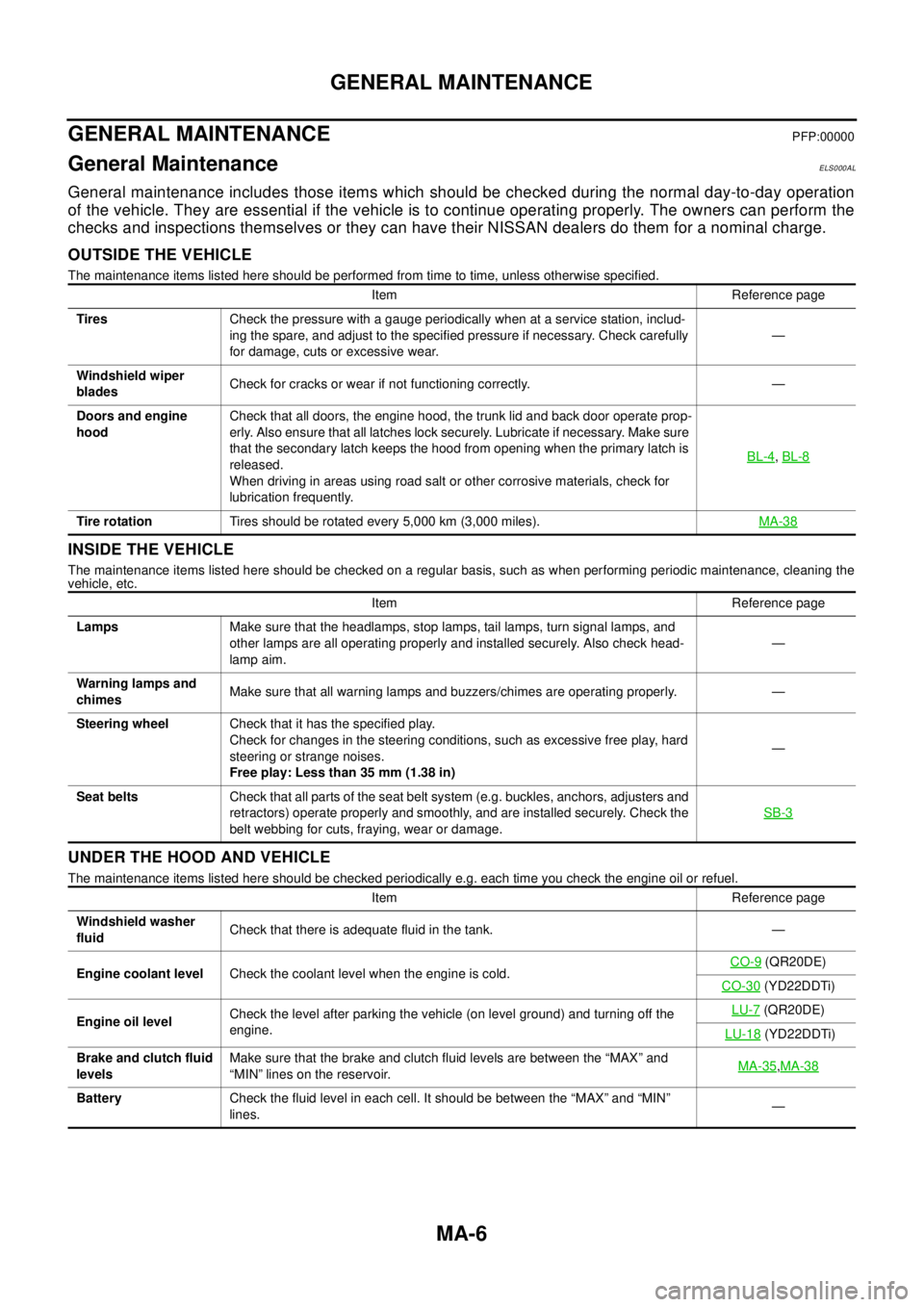
General maintenance includes those items which should be checked during the normal day-to-day operation
of the vehicle. They are essential if the vehicle is to continue operating properly. The owners can perform the
checks and inspections themselves or they can have their NISSAN dealers do them for a nominal charge.
OUTSIDE THE VEHICLE
The maintenance items listed here should be performed from time to time, unless otherwise specified.
INSIDE THE VEHICLE
The maintenance items listed here should be checked on a regular basis, such as when performing periodic maintenance, cleaning the
vehicle, etc.
UNDER THE HOOD AND VEHICLE
The maintenance items listed here should be checked periodically e.g. each time you check the engine oil or refuel.Item Reference page
TiresCheck the pressure with a gauge periodically when at a service station, includ-
ing the spare, and adjust to the specified pressure if necessary. Check carefully
for damage, cuts or excessive wear.—
Windshield wiper
bladesCheck for cracks or wear if not functioning correctly. —
Doors and engine
hoodCheck that all doors, the engine hood, the trunk lid and back door operate prop-
erly. Also ensure that all latches lock securely. Lubricate if necessary. Make sure
that the secondary latch keeps the hood from opening when the primary latch is
released.
When driving in areas using road salt or other corrosive materials, check for
lubrication frequently.BL-4
,BL-8
Tire rotationTires should be rotated every 5,000 km (3,000 miles).MA-38
Item Reference page
LampsMake sure that the headlamps, stop lamps, tail lamps, turn signal lamps, and
other lamps are all operating properly and installed securely. Also check head-
lamp aim.—
Warning lamps and
chimesMake sure that all warning lamps and buzzers/chimes are operating properly. —
Steering wheelCheck that it has the specified play.
Check for changes in the steering conditions, such as excessive free play, hard
steering or strange noises.
Free play: Less than 35 mm (1.38 in)—
Seat beltsCheck that all parts of the seat belt system (e.g. buckles, anchors, adjusters and
retractors) operate properly and smoothly, and are installed securely. Check the
belt webbing for cuts, fraying, wear or damage.SB-3
Item Reference page
Windshield washer
fluidCheck that there is adequate fluid in the tank. —
Engine coolant levelCheck the coolant level when the engine is cold.CO-9
(QR20DE)
CO-30
(YD22DDTi)
Engine oil levelCheck the level after parking the vehicle (on level ground) and turning off the
engine.LU-7
(QR20DE)
LU-18
(YD22DDTi)
Brake and clutch fluid
levelsMake sure that the brake and clutch fluid levels are between the “MAX” and
“MIN” lines on the reservoir.MA-35
,MA-38
BatteryCheck the fluid level in each cell. It should be between the “MAX” and “MIN”
lines.—
Page 2534 of 3066
MA-42
CHASSIS AND BODY MAINTENANCE
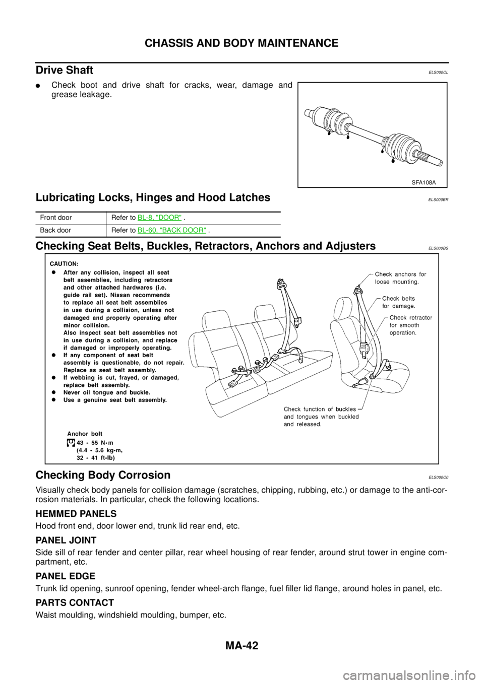
Drive Shaft
ELS000CL
lCheck boot and drive shaft for cracks, wear, damage and
grease leakage.
Lubricating Locks, Hinges and Hood LatchesELS000BR
Checking Seat Belts, Buckles, Retractors, Anchors and AdjustersELS000BS
Checking Body CorrosionELS000C0
Visually check body panels for collision damage (scratches, chipping, rubbing, etc.) or damage to the anti-cor-
rosion materials. In particular, check the following locations.
HEMMED PANELS
Hood front end, door lower end, trunk lid rear end, etc.
PANEL JOINT
Side sill of rear fender and center pillar, rear wheel housing of rear fender, around strut tower in engine com-
partment, etc.
PANEL EDGE
Trunk lid opening, sunroof opening, fender wheel-arch flange, fuel filler lid flange, around holes in panel, etc.
PA R T S C O N TA C T
Waist moulding, windshield moulding, bumper, etc.
SFA108A
Front door Refer toBL-8, "DOOR".
Back door Refer toBL-60, "
BACK DOOR".
Page 2677 of 3066
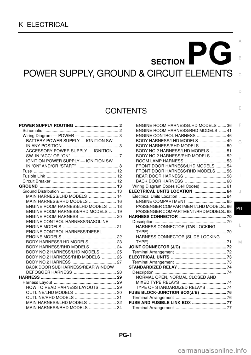
PG-1
POWER SUPPLY, GROUND & CIRCUIT ELEMENTS
K ELECTRICAL
CONTENTS
C
D
E
F
G
H
I
J
L
M
SECTION
A
B
PG
POWER SUPPLY, GROUND & CIRCUIT ELEMENTS
POWER SUPPLY ROUTING ...................................... 2
Schematic ................................................................ 2
Wiring Diagram — POWER — ................................. 3
BATTERY POWER SUPPLY — IGNITION SW.
IN ANY POSITION ................................................ 3
ACCESSORY POWER SUPPLY — IGNITION
SW. IN “ACC” OR “ON” ......................................... 7
IGNITION POWER SUPPLY — IGNITION SW.
IN “ON” AND/OR “START” .................................... 8
Fuse ....................................................................... 12
Fusible Link ............................................................ 12
Circuit Breaker ....................................................... 12
GROUND .................................................................. 13
Ground Distribution ................................................ 13
MAIN HARNESS/LHD MODELS ........................ 14
MAIN HARNESS/RHD MODELS ........................ 16
ENGINE ROOM HARNESS/LHD MODELS ....... 18
ENGINE ROOM HARNESS/RHD MODELS ....... 19
ENGINE ROOM HARNESS ................................ 20
ENGINE CONTROL HARNESS/GASOLINE
ENGINE MODELS .............................................. 21
ENGINE CONTROL HARNESS/DIESEL
ENGINE MODELS .............................................. 22
BODY HARNESS/LHD MODELS ....................... 23
BODY HARNESS/RHD MODELS ....................... 24
BODY NO.2 HARNESS/LHD MODELS .............. 25
BODY NO.2 HARNESS/RHD MODELS ............. 26
BODY NO.2 HARNESS ...................................... 27
BACK DOOR SUB HARNESS/REAR WINDOW
DEFOGGER HARNESS ..................................... 28
HARNESS ................................................................. 29
Harness Layout ...................................................... 29
HOW TO READ HARNESS LAYOUTS ............... 29
OUTLINE/LHD MODELS .................................... 30
OUTLINE/RHD MODELS .................................... 31
MAIN HARNESS/LHD MODELS ........................ 32
MAIN HARNESS/RHD MODELS ........................ 34ENGINE ROOM HARNESS/LHD MODELS ........ 36
ENGINE ROOM HARNESS/RHD MODELS ....... 41
ENGINE CONTROL HARNESS .......................... 46
BODY HARNESS/LHD MODELS ....................... 49
BODY HARNESS/RHD MODELS ....................... 50
BODY NO.2 HARNESS/LHD MODELS .............. 51
BODY NO.2 HARNESS/RHD MODELS .............. 52
ROOM LAMP HARNESS .................................... 53
FRONT DOOR HARNESS/LHD MODELS .......... 54
FRONT DOOR HARNESS/RHD MODELS ......... 56
REAR DOOR HARNESS .................................... 58
BACK DOOR HARNESS .................................... 60
Wiring Diagram Codes (Cell Codes) ...................... 61
ELECTRICAL UNITS LOCATION ............................ 64
Electrical Units Location ......................................... 64
ENGINE COMPARTMENT .................................. 65
PASSENGER COMPARTMENT/LHD MODELS... 66
PASSENGER COMPARTMENT/RHD MODELS... 68
HARNESS CONNECTOR ......................................... 70
Description .............................................................. 70
HARNESS CONNECTOR (TAB-LOCKING
TYPE) .................................................................. 70
HARNESS CONNECTOR (SLIDE-LOCKING
TYPE) .................................................................. 71
JOINT CONNECTOR (J/C) ....................................... 72
Terminal Arrangement ............................................ 72
ELECTRICAL UNITS ................................................ 73
Terminal Arrangement ............................................ 73
STANDARDIZED RELAY .......................................... 74
Description .............................................................. 74
NORMAL OPEN, NORMAL CLOSED AND
MIXED TYPE RELAYS ........................................ 74
TYPE OF STANDARDIZED RELAYS ................. 74
FUSE BLOCK-JUNCTION BOX(J/B) ....................... 76
Terminal Arrangement ............................................ 76
FUSE AND FUSIBLE LINK BOX .............................. 77
Terminal Arrangement ............................................ 77