relay NISSAN X-TRAIL 2003 Electronic Repair Manual
[x] Cancel search | Manufacturer: NISSAN, Model Year: 2003, Model line: X-TRAIL, Model: NISSAN X-TRAIL 2003Pages: 3066, PDF Size: 51.47 MB
Page 456 of 3066
![NISSAN X-TRAIL 2003 Electronic Repair Manual AT-450
[ALL]
A/T SHIFT LOCK SYSTEM
6.CHECK RELAY CIRCUIT
1. Turn ignition switch to ON.
Check voltage between terminal 7 - 6 and 5 - 6.
OK or NG
OK >> GO TO 7
NG >> Replace A/T device.
7.CHECKPARKPOSI](/img/5/57402/w960_57402-455.png "NISSAN X-TRAIL 2003 Electronic Repair Manual AT-450
[ALL]
A/T SHIFT LOCK SYSTEM
6.CHECK RELAY CIRCUIT
1. Turn ignition switch to ON.
Check voltage between terminal 7 - 6 and 5 - 6.
OK or NG
OK >> GO TO 7
NG >> Replace A/T device.
7.CHECKPARKPOSI")
AT-450
[ALL]
A/T SHIFT LOCK SYSTEM
6.CHECK RELAY CIRCUIT
1. Turn ignition switch to ON.
Check voltage between terminal 7 - 6 and 5 - 6.
OK or NG
OK >> GO TO 7
NG >> Replace A/T device.
7.CHECKPARKPOSITIONSWITCH
Refer toAT-450, "
A/T DEVICE CHECK".
OK or NG
OK >> GO TO 8
NG >> Replace A/T device.
8.CHECK SHIFT LOCK SOLENOID
Refer toAT-450, "
A/T DEVICE CHECK".
OK or NG
OK >> GO TO 9
NG >> Replace A/T device.
9.SHIFT LOCK OPERATION
1. Reconnect shift lock harness connector.
2. Turn ignition switch from “OFF” to “ON” position. (Do not start engine.)
3. Recheck shift lock operation.
OK or NG
OK >>INSPECTION END
NG >> 1. Perform A/T device input/output signal inspection test.
2. If NG, recheck harness connector connection.
A/T DEVICE CHECK
1. Shift Lock Solenoid
lCheck operation sound.
When ignition switch is turned to “ON” position and selector lever is set in “P” position.
SCIA0785E
Brake pedal Operation sound
Depressed Yes
Released No
Page 594 of 3066

ATC-16
REFRIGERATION SYSTEM
REFRIGERATION SYSTEM
PFP:KA990
Refrigerant CycleEJS000TD
REFRIGERANT FLOW
The refrigerant flows in the standard pattern, that is, through the compressor, the condenser with liquid tank,
through the evaporator, and back to the compressor. The refrigerant evaporation through the evaporator coil is
controlled by an externally equalized expansion valve, located inside the evaporator case.
FREEZE PROTECTION (WITH GASOLINE ENGINE: CWV-615M COMPRESSOR)
Under normal operating conditions, when the A/C is switched on, the compressor runs continuously, and the
evaporator pressure, and therefore, temperature is controlled by the V-6 variable displacement compressor to
prevent freeze up.
Refrigerant System ProtectionEJS000TE
REFRIGERANT PRESSURE SENSOR (WITH GASOLINE ENGINE: CWV-615M COMPRESSOR)
The refrigerant system is protected against excessively high or low pressures by the refrigerant pressure sen-
sor, located on the liquid tank. If the system pressure rises above, or falls below the specifications, the refriger-
ant pressure sensor detects the pressure inside the refrigerant line and sends the voltage signal to the ECM.
ECM makes the A/C relay go OFF and stops the compressor when pressure on the high pressure side
detected by refrigerant pressure sensor is over about 2,746 kPa (28 kg/cm
2, 398 psi), or below about 134 kPa
(1.4 kg/cm
2,20psi).
DUAL-PRESSURE SWITCH (WITH DIESEL ENGINE: DKV-11G COMPRESSOR)
The refrigerant system is protected against excessively high or low pressures by the dual-pressure switch,
located on the liquid tank. If the system pressure rises above or falls below the specifications, the dual-pres-
sure switch opens to interrupt the compressor operation.
PRESSURE RELIEF VALVE (WITH GASOLINE ENGINE: CWV-615M COMPRESSOR)
The refrigerant system is also protected by a pressure relief valve, located in the rear head of the compressor.
When the pressure of refrigerant in the system increases to an abnormal level [more than 3,727 kPa (38 kg/
Page 654 of 3066
ATC-76
TROUBLE DIAGNOSIS
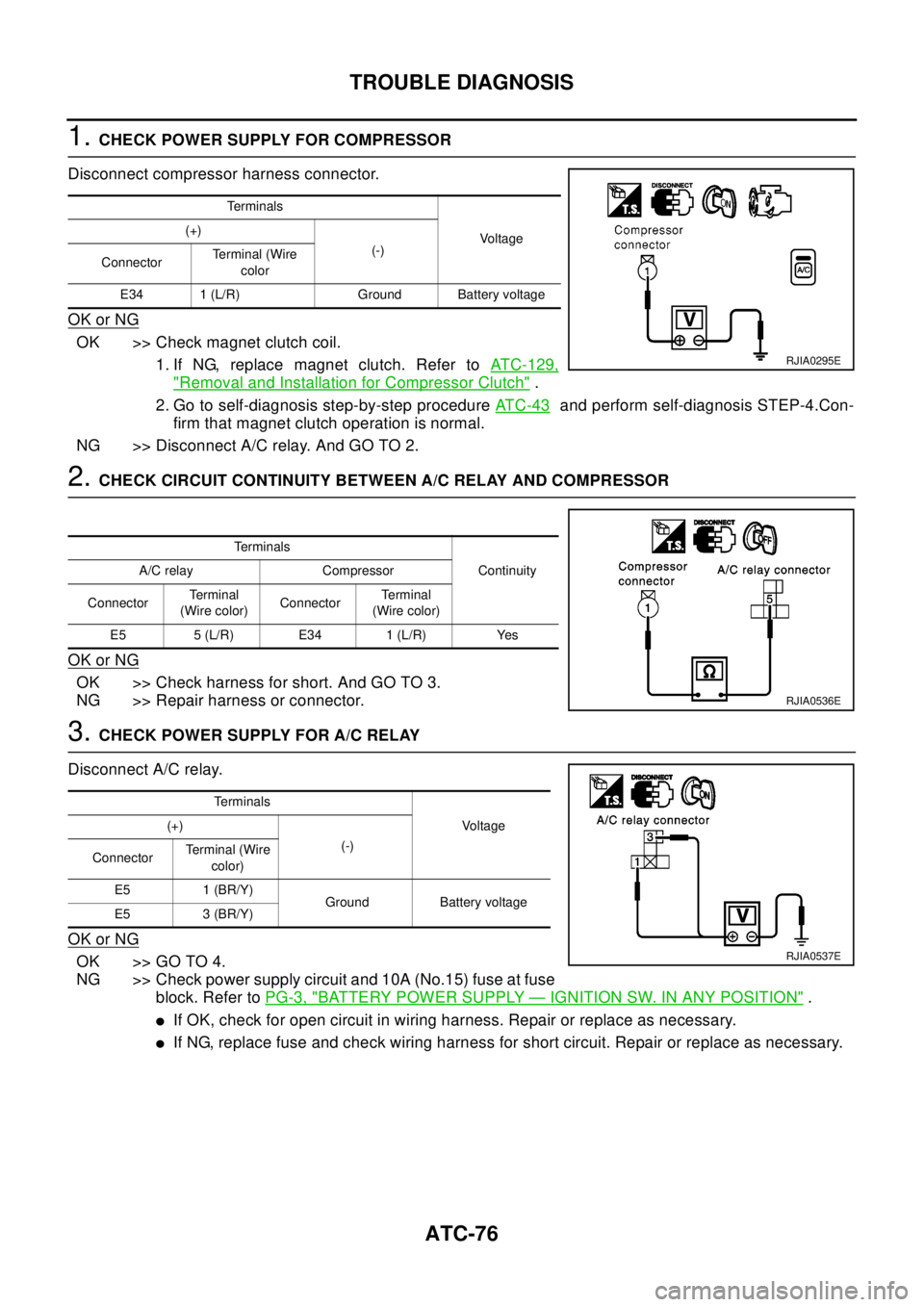
1.CHECK POWER SUPPLY FOR COMPRESSOR
Disconnect compressor harness connector.
OK or NG
OK >> Check magnet clutch coil.
1. If NG, replace magnet clutch. Refer toATC-129,
"Removal and Installation for Compressor Clutch".
2. Go to self-diagnosis step-by-step procedureAT C - 4 3
and perform self-diagnosis STEP-4.Con-
firm that magnet clutch operation is normal.
NG >>DisconnectA/Crelay.AndGOTO2.
2.CHECK CIRCUIT CONTINUITY BETWEEN A/C RELAY AND COMPRESSOR
OK or NG
OK >> Check harness for short. And GO TO 3.
NG >> Repair harness or connector.
3.CHECK POWER SUPPLY FOR A/C RELAY
Disconnect A/C relay.
OK or NG
OK >> GO TO 4.
NG >> Check power supply circuit and 10A (No.15) fuse at fuse
block. Refer toPG-3, "
BATTERY POWER SUPPLY—IGNITION SW. IN ANY POSITION".
lIf OK, check for open circuit in wiring harness. Repair or replace as necessary.
lIf NG, replace fuse and check wiring harness for short circuit. Repair or replace as necessary.
Te r m i n a l s
Vo l ta g e (+)
(-)
ConnectorTerminal (Wire
color
E34 1 (L/R) Ground Battery voltage
RJIA0295E
Te r m i n a l s
Continuity A/C relay Compressor
ConnectorTe r m i n a l
(Wire color)ConnectorTe r m i n a l
(Wire color)
E5 5 (L/R) E34 1 (L/R) Yes
RJIA0536E
Te r m i n a l s
Vo l ta g e (+)
(-)
ConnectorTerminal (Wire
color)
E5 1 (BR/Y)
Ground Battery voltage
E5 3 (BR/Y)
RJIA0537E
Page 655 of 3066
TROUBLE DIAGNOSIS
ATC-77
C
D
E
F
G
H
I
K
L
MA
B
AT C
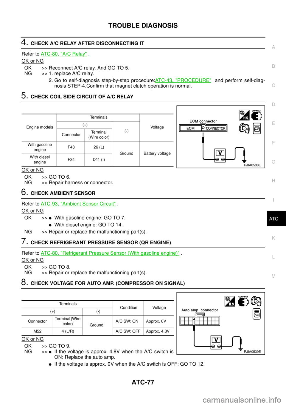
4.CHECK A/C RELAY AFTER DISCONNECTING IT
Refer toAT C - 8 0 , "
A/C Relay".
OK or NG
OK >>ReconnectA/Crelay.AndGOTO5.
NG >> 1. replace A/C relay.
2. Go to self-diagnosis step-by-step procedure:ATC-43, "
PROCEDURE"and perform self-diag-
nosis STEP-4.Confirm that magnet clutch operation is normal.
5.CHECK COIL SIDE CIRCUIT OF A/C RELAY
OK or NG
OK >> GO TO 6.
NG >> Repair harness or connector.
6.CHECK AMBIENT SENSOR
Refer toAT C - 9 3 , "
Ambient Sensor Circuit".
OK or NG
OK >>lWith gasoline engine: GO TO 7.
lWith diesel engine: GO TO 14.
NG >> Repair or replace the malfunctioning part(s).
7.CHECK REFRIGERANT PRESSURE SENSOR (QR ENGINE)
Refer toAT C - 8 0 , "
Refrigerant Pressure Sensor (With gasoline engine)".
OK or NG
OK >> GO TO 8.
NG >> Repair or replace the malfunctioning part(s).
8.CHECK VOLTAGE FOR AUTO AMP. (COMPRESSOR ON SIGNAL)
OK or NG
OK >> GO TO 9.
NG >>
lIf the voltage is approx. 4.8V when the A/C switch is
ON: Replace the auto amp.
lIf the voltage is approx. 0V when the A/C switch is OFF: GO TO 12.
Engine modelsTe r m i n a l s
Vo l ta g e (+)
(-)
ConnectorTe r m i n a l
(Wire color)
With gasoline
engineF43 26 (L)
Ground Battery voltage
With diesel
engineF34 D11 (I)
RJIA0538E
Te r m i n a l s
Condition Voltage
(+) (-)
ConnectorTerminal (Wire
color)
GroundA/C SW: ON Approx. 0V
M52 4 (L/R) A/C SW: OFF Approx. 4.8V
RJIA0539E
Page 658 of 3066
ATC-80
TROUBLE DIAGNOSIS
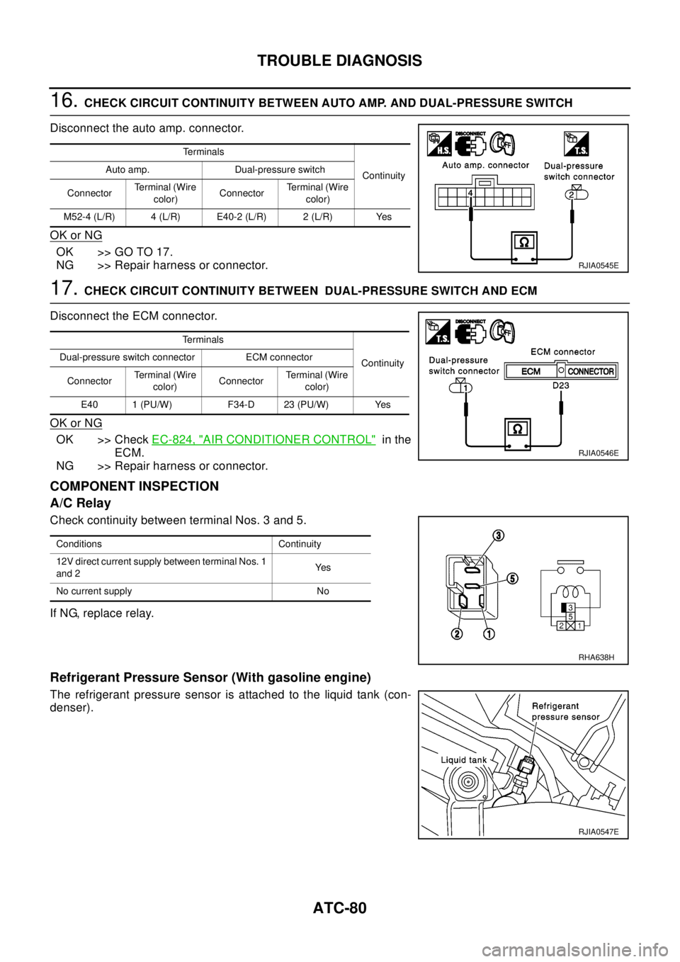
16.CHECK CIRCUIT CONTINUITY BETWEEN AUTO AMP. AND DUAL-PRESSURE SWITCH
Disconnect the auto amp. connector.
OK or NG
OK >> GO TO 17.
NG >> Repair harness or connector.
17.CHECK CIRCUIT CONTINUITY BETWEEN DUAL-PRESSURE SWITCH AND ECM
Disconnect the ECM connector.
OK or NG
OK >> CheckEC-824, "AIR CONDITIONER CONTROL"in the
ECM.
NG >> Repair harness or connector.
COMPONENT INSPECTION
A/C Relay
Check continuity between terminal Nos. 3 and 5.
If NG, replace relay.
Refrigerant Pressure Sensor (With gasoline engine)
The refrigerant pressure sensor is attached to the liquid tank (con-
denser).
Te r m i n a l s
Continuity Auto amp. Dual-pressure switch
ConnectorTerminal (Wire
color)ConnectorTerminal (Wire
color)
M52-4 (L/R) 4 (L/R) E40-2 (L/R) 2 (L/R) Yes
RJIA0545E
Te r m i n a l s
Continuity Dual-pressure switch connector ECM connector
ConnectorTerminal (Wire
color)ConnectorTerminal (Wire
color)
E40 1 (PU/W) F34-D 23 (PU/W) Yes
RJIA0546E
Conditions Continuity
12V direct current supply between terminal Nos. 1
and 2Ye s
No current supply No
RHA638H
RJIA0547E
Page 741 of 3066

TIME CONTROL UNIT
BCS-3
C
D
E
F
G
H
I
J
L
MA
B
BCS
TIME CONTROL UNITPFP:28491
DescriptionEKS002ZU
OUTLINE
The time control unit totally controls the following body electrical system operations.
lWarning chime
lRear defogger
lPower door lock
lInterior lamp
INPUT/OUTPUT
System Input Output
PowerdoorlockDoor lock and unlock switch
Door switches
Door unlock sensor
Door key cylinder switch (driver side)Door lock actuators
Warning chimeKey switch (Insert)
Ignition switch (ON)
Lighting switch (1st)
Front door switch (driver side)
Door unlock sensorWarning chime (located in time control unit)
Rear window defoggerIgnition switch (ON)
Rear window defogger switchRear window defogger relay
Interior lampDoor switches
Front door unlock sensor
Ignition switch (ON)
Key switch (Insert)Interior lamp
Page 743 of 3066

TIME CONTROL UNIT
BCS-5
C
D
E
F
G
H
I
J
L
MA
B
BCS
Time Control Unit Inspection TableEKS002ZW
Te r m i n a l
No.Wire
colorConnections Operation conditionVo l ta g e
(Approxi-
mate values)
1 L/B Power source (Fuse) — 12V
3 L/Y Super lock actuator Door key cylinder switchFree 0V
Unlocked 12V
4G/RPassenger and rear doors lock
actuatorDoor lock/unlock switchFree 0V
Unlocked 12V
6 Y/R Super lock actuator Door key cylinder switchFree 0V
Locked 12V
10 W Power source (C/B) — 12V
11 L Driver's door lock actuator Door lock/unlock switchFree 0V
Unlocked 12V
14 R/B Door lock actuator Door lock/unlock switchFree 0V
Locked 12V
16 B Ground — 0V
17 G Ignition switch (ON) — 12V
18 W/L Ignition key switch (Insert) Key inserted®key removed from IGN key cylinder 12V®0V
19 R/L Lighting switch 1ST, 2ND position: ON®OFF 12V®0V
20 GY Door lock/Unlock switch Neutral®Locks 5V®0V
23 PU Door lock/Unlock switch Neutral®Unlocks 5V®0V
24 OR/L Door key cylinder switch OFF (Neutral)®ON (Locked) 5V®0V
25 W/L Door key cylinder switch OFF (Neutral)®ON (Unlocked) 5V®0V
26 R/Y Interior room lampWhen interior room lamp is operated using remote control-
ler (Lamp switch is “DOOR” position)12V®0V
27 G/W Rear window defogger relay OFF®ON (Ignition key is in “ON” position) 12V®0V
28 Y/G Driver door unlock sensor Driver door: Locked®Unlocked 5V®0V
29 Y/L Passenger door unlock sensor Passenger door: Locked®Unlocked 5V®0V
30 R Doorswitchdriverside OFF(closed)®ON (open) 5V®0V
31 R/W Passenger and rear doors switch OFF (closed)®ON (open) 5V®0V
32 OR Multi-remote control unitRemote controller lock button is pushed.
(Ignition switch is not at “ON” position)0V®5V
33 P/L Multi-remote control unitRemote controller unlock button is pushed.
(Ignition switch is not at “ON” position)0V®5V
35 LG/B Rear window defogger switch OFF®ON 5V®0V
Page 869 of 3066

BRC-1
BRAKE CONTROL SYSTEM
F BRAKES
CONTENTS
C
D
E
G
H
I
J
K
L
M
SECTION
A
B
BRC
BRAKE CONTROL SYSTEM
4WD/ABS
PRECAUTIONS .......................................................... 4
Precautions for brake system ................................... 4
Precautions for brake control ................................... 4
PREPARATION ........................................................... 5
Special Service Tools ............................................... 5
ALL MODE 4X4 SYSTEM .......................................... 6
System Description .................................................. 6
ABS FUNCTION ................................................... 6
4WD FUNCTION ................................................... 6
Control System Diagram .......................................... 6
TROUBLE DIAGNOSIS .............................................. 7
Fail-safe Function ..................................................... 7
How to Proceed with Trouble Diagnosis .................. 7
BASIC CONCEPT ................................................. 7
DIAGNOSIS FLOW ............................................... 8
ASKING COMPLAINTS ........................................ 9
TROUBLE DIAGNOSIS SHEET - EXAMPLE ....... 9
Component Parts Location ..................................... 10
Schematic ...............................................................11
Wiring Diagram — ABS — ..................................... 12
Trouble Diagnosis Chart by Symptom .................... 18
4WD/ABS Control Unit Input/Output Signal Stan-
dard ........................................................................ 19
4WD/ABS CONTROL UINT CONNECTOR TER-
MINAL ARRANGEMENT .................................... 19
REFERENCE STANDARD TABLE ..................... 19
CONSULT-II Functions ........................................... 23
CONSULT-II FUNCTION APPLICATION TABLE... 23
SELF-DIAGNOSIS .............................................. 24
DATA MONITOR ................................................. 26
ACTIVE TEST ..................................................... 29
Component Inspection ........................................... 30
ABS ACTUATOR ................................................ 30
4WD SOLENOID VALVE .................................... 32
Basic Inspection ..................................................... 32
BASIC INSPECTION 1 BRAKE FLUID LEVEL
AND LEAKAGE INSPECTION ............................ 32
BASIC INSPECTION 2 INSPECTION FOR
LOOSE POWER SUPPLY TERMINAL ............... 32BASIC INSPECTION 3 ABS/4WD WARNING
LAMP INSPECTION ............................................ 32
Wheel Speed Sensor System ................................. 32
INSPECTION PROCEDURE .............................. 32
Control Module Power Supply System ................... 34
INSPECTION PROCEDURE .............................. 34
G -Sensor System (4WD models) .......................... 34
INSPECTION PROCEDURE .............................. 34
4WD SOLENOID, ACTUATOR RELAY SYSTEM... 35
4WD MODE SWITCH SYSTEM ............................. 37
Trouble Diagnoses for Symptoms .......................... 38
4WD INDICATOR LAMP DOES NOT COME ON
FORAPPROXIMATELY1SECONDWHENTHE
IGNITION SWITCH IS TURNED TO ON ............. 38
4WD WARNING LAMP DOES NOT ILLUMINATE
WITH IGNITION ON ............................................ 39
4WD WARNING LAMP DOES NOT GO OUT
SEVERAL SECONDS AFTER ENGINE
STARTED.(4WD MODE INDICATOR LAMP
GOES OUT) ........................................................ 39
HEAVY TIGHT-CORNER BRAKING SYMPTOM
OCCURS WHEN THE VEHICLE IS DRIVEN IN
AUTO MODE AND THE STEERING WHEEL IS
TURNED FULLY TO EITHER SIDE AFTER THE
ENGINE IS STARTED ......................................... 39
4WD MODES CANNOT BE SWITCHED AFTER
ENGINE IS STARTED ......................................... 41
WHILE DRIVING, 4WD WARNING LAMP
FLASHES RAPIDLY. (WHEN IT FLASHERSFOR
APPROX. ONE MINUTE, THEN DOES NOT
ILLUMINATE.) ..................................................... 41
WHILE DRIVING, 4WD WARNING LAMP
FLASHES SLOWLY. (WHEN IT CONTINUES TO
ILLUMINATE UNTIL ENGINE TURNS OFF.) ...... 41
VEHICLE DOES NOT ENTER 4WD MODE
EVEN THOUGH 4WD WARNING LAMP IS OFF.... 41
TIGHT-CONER BRAKING SYMPTOM OCCURS
WHEN THE VEHICLE IS STARTED IN AUTO
WARNING LAMP REMAIN OFF). ....................... 42
4WD ACTUATOR RELAY (4WD SOLENOID
Page 870 of 3066

BRC-2
ACTUATOR RELAY) TURNS ON/OFF FRE-
QUENTLY ............................................................ 42
ABS warning lamp does not illuminate. (ABS warn-
ing lamp does not come on when the ignition switch
is turned ON.) ......................................................... 42
ABS warning lamp illuminates with ignition ON, but
does not illuminates after a few seconds. (ABS
warning lamp has illuminated.) ............................... 42
4WD warning lamp does not illuminate with ignition
ON. ......................................................................... 43
4WD warning lamp does not go out several seconds
after engine is started. (Drive mode indicator lamp
goes out.) ................................................................ 43
Heavy tight-corner braking symptom occurs when
the vehicle is driven in AUTO mode and the steering
wheel is turned fully to either side after the engine
is started. ................................................................ 44
Drive modes cannot be switched after engine is
started. .................................................................... 45
Wheel driving, 4WD warning lamp flashes rapidly.
(When it flashes for Approx. one minute, then does
not illuminate.) ........................................................ 45
Wheel driving, 4WD warning lamp flashes slowly.
(When it continues to illuminate until engine turns
OFF.) ....................................................................... 45
Vehicle does not enter 4WD mode even though
4WD warning lamp is off. ........................................ 46
Tight-corner braking symptom occurs when the
vehicle is started in AUTO mode (4WD warning lamp
remain OFF). .......................................................... 46
E-TS actuator relay (4WD solenoid actuator relay)
turns ON/OFF frequently. ........................................ 46
Inspection of drive mode change-over switch path... 47
WHEEL SENSORS ................................................... 48
Removal and Installation ........................................ 48
G-SENSOR (4WD MODEL ONLY) ............................ 49
Removal and Installation ........................................ 49
SENSOR ROTOR ...................................................... 50
Removal and Installation ........................................ 50
REMOVAL ........................................................... 50
INSTALLATION .................................................... 50
ACTUATOR ............................................................... 51
Removal and Installation ........................................ 51
REMOVAL ........................................................... 51
INSTALLATION .................................................... 51
ESP/TCS/ABS
PRECAUTIONS ......................................................... 52
Precautions for Supplemental Restraint System
(SRS) “AIR BAG” and “SEAT BELT PRE-TEN-
SIONER” ................................................................. 52
Precautions for Brake System ................................ 52
Precautions for Brake Control ................................ 52
Precautions for CAN System .................................. 53
FOR INSPECTION .............................................. 53
FOR HARNESS REPAIR .................................... 53ON-VEHICLE SERVICE ............................................54
Adjustment of Neutral Position of Steering Angle
Sensor .....................................................................54
GENERAL INFORMATION .......................................56
Fail-Safe ..................................................................56
ABS SYSTEM ......................................................56
ESP/TCS SYSTEM ..............................................56
Hydraulic Circuit ......................................................56
ABS Functions ........................................................56
TCS Functions ........................................................57
ESP Functions ........................................................57
System Diagram .....................................................58
CAN COMMUNICATION ...........................................59
System Description .................................................59
FOR M/T MODELS ..............................................59
TROUBLE DIAGNOSIS ............................................60
How to Perform Trouble Diagnoses for Quick and
Accurate Repair ......................................................60
INTRODUCTION .................................................60
WORK FLOW ......................................................61
ASKING COMPLAINTS .......................................62
EXAMPLE OF DIAGNOSIS SHEET ....................62
Component Parts and Harness Connector Location... 63
Schematic ...............................................................64
Wiring Diagram —ESP/TCS/ABS— .....................65
Control Unit Input/Output Signal Standard ..............71
STANDARDS USING A CIRCUIT TESTER AND
OSCILLOSCOPE .................................................71
STANDARDS WITH CONSULT-II ........................75
Functions of CONSULT-II .......................................77
CONSULT-II MAINLY FUNCTION APPLICA-
TION TO ESP/TCS/ABS ......................................77
SELF-DIAGNOSIS ...............................................78
DATA MONITOR ..................................................81
ACTIVE TEST ......................................................84
For Correct and Quick Diagnosis ............................88
PRECAUTIONS FOR TROUBLE DIAGNOSIS ... 88
Basic Inspection ......................................................89
PRELIMINARY CHECK 1: (BRAKE FLUID
LEVEL AND LEAK INSPECTION) .......................89
PRELIMINARY CHECK 2: (INSPECTION FOR
LOOSE POWER SUPPLY TERMINAL) ...............89
PRELIMINARY CHECK 3: (INSPECTION FOR
ABS WARNING LAMP, ESP OFF INDICATOR
LAMP, AND SLIP INDICATOR LAMP) .................89
Inspection 1 Wheel Speed Sensor and Circuit .......90
Inspection 2 Engine System ...................................92
Inspection 3 ESP/TCS/ABS Control Unit System ...92
Inspection 4 Pressure Sensor and the Circuit
between Pressure Sensor and ESP/TCS/ABS Con-
trol Unit. ...................................................................93
Inspection 5 Steering Angle Sensor and the Circuit
between Steering Angle Sensor and ESP/TCS/ABS
Control Unit. ............................................................94
Inspection 6 Yaw Rate Sensor/ Side G sensor and
the Circuit between Yaw Rate Sensor/ Side G sen-
sor and ESP/TCS/ABS Control Unit. ......................95
Inspection 7 Solenoid Valve, ESP Switch-over Sole-
Page 871 of 3066

BRC-3
C
D
E
G
H
I
J
K
L
MA
B
BRC noid Valve and Circuit ............................................ 97
Inspection 8 Actuator Motor, Motor Relay and Circuit
. 100
Inspection 9 Actuator Relay and Circuit ............... 102
Inspection 10 Stop Lamp Switch and Circuit ........ 104
Inspection 11 ESP/TCS/ABS Control Unit Power
Supply Circuit ....................................................... 104
Inspection 12 When “EMERGENCY BRAKE” is
indicated in the Self-Diagnosis Results ................ 106
Inspection 13 When “ST ANG SEN SIGNAL” is Indi-
cated in the Self-Diagnosis Results ..................... 106
Inspection 14 Brake Fluid Level of Reservoir Tank,
Communication Circuit between ESP/TCS/ABS
Control Unit and Brake Fluid Level Warning Switch. 107
Inspection 15 CAN Communication Circuit, ESP/
TCS/ABS Control Unit and Steering Angle Sensor. 108
Component Check ............................................... 109
ESP OFF SWITCH ............................................ 109
ESP/TCS/ABS RELAY BOX ............................. 109
ESP/TCS/ABS ACTUATOR ............................... 110
Symptom 1: ABS Works Frequently. ..................... 112
Symptom 2: Unexpected Pedal Action .................. 112
Symptom 3: Longer Stopping Distance ................. 113
Symptom 4: ABS Does Not Work. ........................ 114
Symptom 5: Pedal Vibration and Noise ................ 114
Symptom 6: ESP OFF Indicator Lamp Does Not Illu-minate ...................................................................115
Symptom 7: SLIP Indicator Lamp Does Not Illumi-
nate .......................................................................116
Symptom 8: During ESP/TCS/ABS Control, Vehicle
Behavior is Jerky. .................................................116
ESP/TCS/ABS CONTROL UNIT ............................118
Removal and Installation ......................................118
REMOVAL .........................................................118
INSTALLATION .................................................118
WHEEL SPEED SENSORS ....................................119
Removal and Installation ......................................119
SENSOR ROTOR ...................................................120
Removal and Installation ......................................120
REMOVAL .........................................................120
INSTALLATION .................................................120
ESP/TCS/ABS ACTUATOR AND RELAY BOX .....121
Removal and Installation ......................................121
YAW RATE/SIDE G SENSOR .................................122
Removal and Installation ......................................122
REMOVAL .........................................................122
INSTALLATION .................................................122
ESP OFF SWITCH ..................................................123
Removal and Installation ......................................123
REMOVAL .........................................................123
INSTALLATION .................................................123