door lock NISSAN X-TRAIL 2003 Electronic Service Manual
[x] Cancel search | Manufacturer: NISSAN, Model Year: 2003, Model line: X-TRAIL, Model: NISSAN X-TRAIL 2003Pages: 3066, PDF Size: 51.47 MB
Page 787 of 3066
POWER DOOR LOCK — SUPER LOCK —
BL-43
C
D
E
F
G
H
J
K
L
MA
B
BL
NATS Release Signal CheckEIS001SN
1.CHECK NATS SIGNAL CIRCUIT
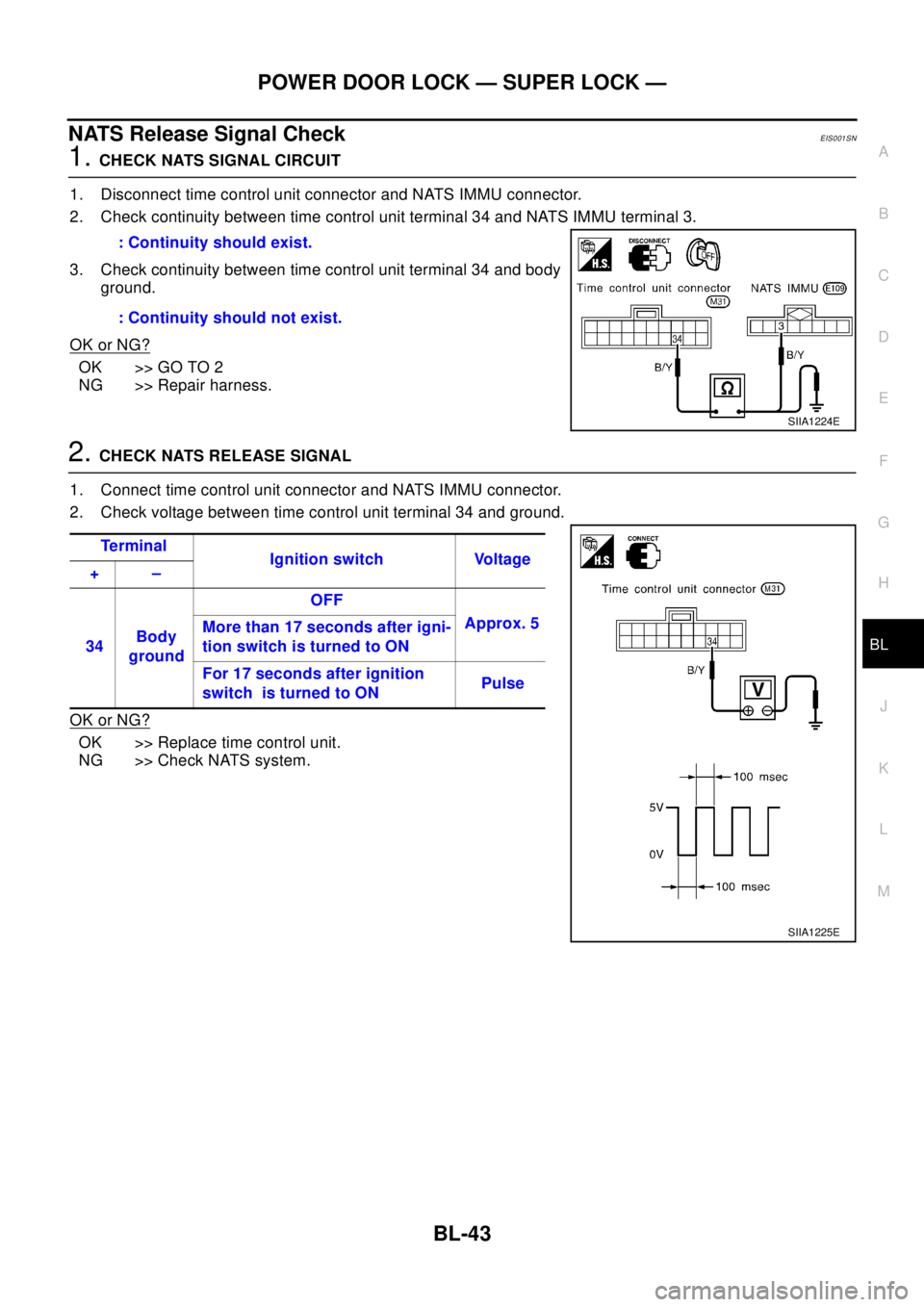
1. Disconnect time control unit connector and NATS IMMU connector.
2. Check continuity between time control unit terminal 34 and NATS IMMU terminal 3.
3. Check continuity between time control unit terminal 34 and body
ground.
OK or NG?
OK >> GO TO 2
NG >> Repair harness.
2.CHECK NATS RELEASE SIGNAL
1. Connect time control unit connector and NATS IMMU connector.
2. Check voltage between time control unit terminal 34 and ground.
OK or NG?
OK >> Replace time control unit.
NG >> Check NATS system.: Continuity should exist.
: Continuity should not exist.
SIIA1224E
Te r m i n a l
Ignition switch Voltage
+–
34Body
groundOFF
Approx. 5
More than 17 seconds after igni-
tion switch is turned to ON
For 17 seconds after ignition
switch is turned to ONPulse
SIIA1225E
Page 788 of 3066
BL-44
POWER DOOR LOCK — SUPER LOCK —
Ignition Switch “ON” Circuit Check
EIS001SP
1.CHECK IGNITION ON SIGNAL
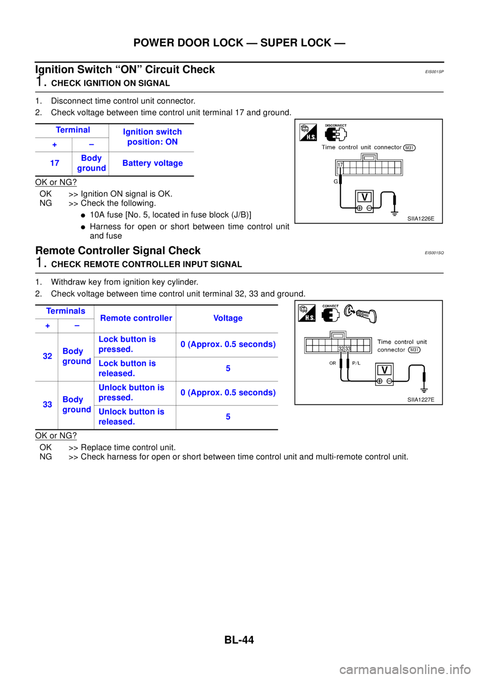
1. Disconnect time control unit connector.
2. Check voltage between time control unit terminal 17 and ground.
OK or NG?
OK >> Ignition ON signal is OK.
NG >> Check the following.
l10A fuse [No. 5, located in fuse block (J/B)]
lHarness for open or short between time control unit
and fuse
Remote Controller Signal CheckEIS001SQ
1.CHECK REMOTE CONTROLLER INPUT SIGNAL
1. Withdraw key from ignition key cylinder.
2. Check voltage between time control unit terminal 32, 33 and ground.
OK or NG?
OK >> Replace time control unit.
NG >> Check harness for open or short between time control unit and multi-remote control unit.Te r m i n a l
Ignition switch
position: ON
+–
17Body
groundBattery voltage
SIIA1226E
Te r m i n a l s
Remote controller Voltage
+–
32Body
groundLock button is
pressed.0 (Approx. 0.5 seconds)
Lock button is
released.5
33Body
groundUnlock button is
pressed.0 (Approx. 0.5 seconds)
Unlock button is
released.5
SIIA1227E
Page 789 of 3066
MULTI-REMOTE CONTROL SYSTEM
BL-45
C
D
E
F
G
H
J
K
L
MA
B
BL
MULTI-REMOTE CONTROL SYSTEMPFP:28596
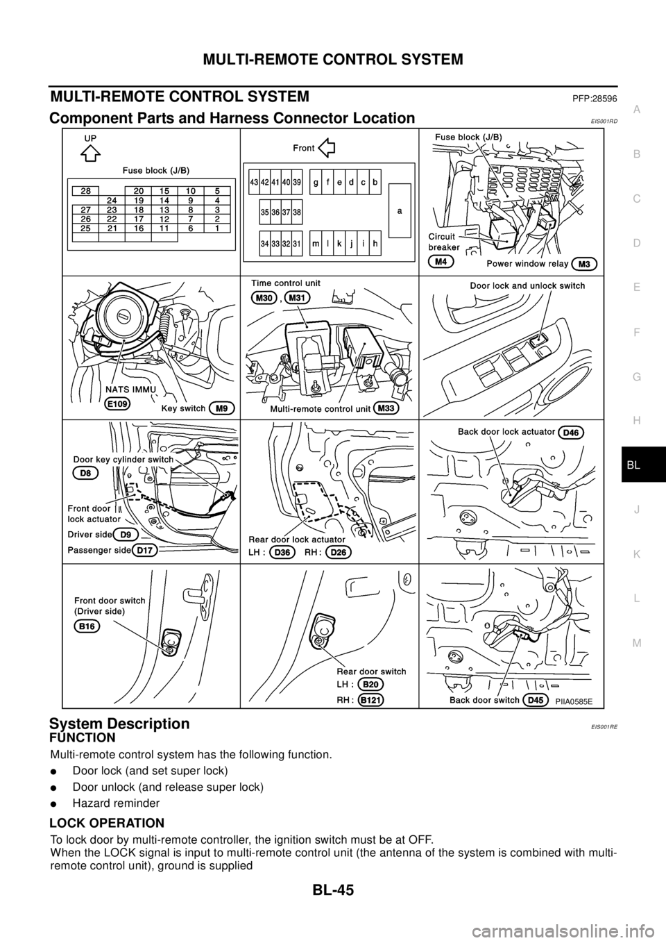
Component Parts and Harness Connector LocationEIS001RD
System DescriptionEIS001RE
FUNCTION
Multi-remote control system has the following function.
lDoor lock (and set super lock)
lDoor unlock (and release super lock)
lHazard reminder
LOCK OPERATION
To lock door by multi-remote controller, the ignition switch must be at OFF.
When the LOCK signal is input to multi-remote control unit (the antenna of the system is combined with multi-
remote control unit), ground is supplied
PIIA0585E
Page 790 of 3066
BL-46
MULTI-REMOTE CONTROL SYSTEM
lthrough multi-remote control unit terminal 5
lto time control unit terminal 32.
Then time control unit operates to lock doors and set super lock (models with super lock).
UNLOCK OPERATION
When the UNLOCK signal is input to multi-remote control unit (the antenna of the system is combined with
multi-remote control unit), ground is supplied
lthrough multi-remote control unit terminal 6
lto time control unit terminal 33.
Time control unit operates to unlock driver's door and release super lock (models with super lock).
Then, if an unlock signal is sent from the remote controller again within 5 seconds, all other doors will be
unlocked.
HAZARD REMINDER
When the doors are locked or unlocked by multi-remote controller (signal from driver side unlock sensor), sup-
ply power to hazard warning lamp flashes as follows
lLock operation: Flash once
lUnlock operation: Flash twice
MULTI-REMOTE CONTROLLER ID CODE ENTRY
A maximum of four remote controllers can be entered.
To enter ID code entry, the following signals must be input to the multi-remote control unit.
lIgnition switch (ON)
lSignal from remote controller
For detailed procedure, refer toBL-52, "
ID Code Entry Procedure".
Page 793 of 3066
MULTI-REMOTE CONTROL SYSTEM
BL-49
C
D
E
F
G
H
J
K
L
MA
B
BL
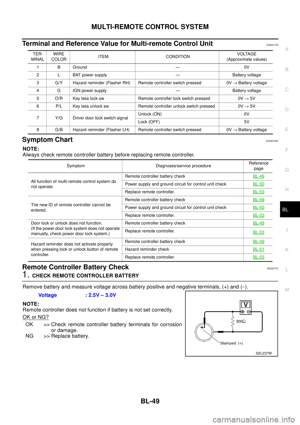
Terminal and Reference Value for Multi-remote Control UnitEIS001TQ
Symptom ChartEIS001RG
NOTE:
Always check remote controller battery before replacing remote controller.
Remote Controller Battery CheckEIS0 01T 3
1.CHECK REMOTE CONTROLLER BATTERY
Remove battery and measure voltage across battery positive and negative terminals, (+) and (-).
NOTE:
Remote controller does not function if battery is not set correctly.
OK or NG?
OK >> Check remote controller battery terminals for corrosion
or damage.
NG >> Replace battery.
TER-
MINALWIRE
COLORITEM CONDITIONVOLTAGE
(Approximate values)
1 B Ground — 0V
2 L BAT power supply — Battery voltage
3 G/Y Hazard reminder (Flasher RH) Remote controller switch pressed 0V®Battery voltage
4 G IGN power supply — Battery voltage
5 O/R Key less lock sw Remote controller lock switch pressed 0V®5V
6 P/L Key less unlock sw Remote controller unlock switch pressed 0V®5V
7 Y/G Driver door lock switch signalUnlock (ON) 0V
Lock (OFF) 5V
8 G/B Hazard reminder (Flasher LH) Remote controller switch pressed 0V®Battery voltage
Symptom Diagnoses/service procedureReference
page
All function of multi-remote control system do
not operate.Remote controller battery checkBL-49
Power supply and ground circuit for control unit checkBL-50
Replace remote controller.BL-53
The new ID of remote controller cannot be
entered.Remote controller battery checkBL-49Power supply and ground circuit for control unit checkBL-50
Replace remote controller.BL-53
Door lock or unlock does not function.
(If the power door lock system does not operate
manually, check power door lock system.)Remote controller battery checkBL-49
Replace remote controller.
BL-53
Hazard reminder does not activate properly
when pressing lock or unlock button of remote
controller.Remote controller battery checkBL-49
Hazard reminder checkBL-51
Replace remote controller.BL-53
Voltage : 2.5V – 3.0V
SEL237W
Page 798 of 3066
BL-54
FRONT DOOR LOCK
FRONT DOOR LOCK
PFP:80502
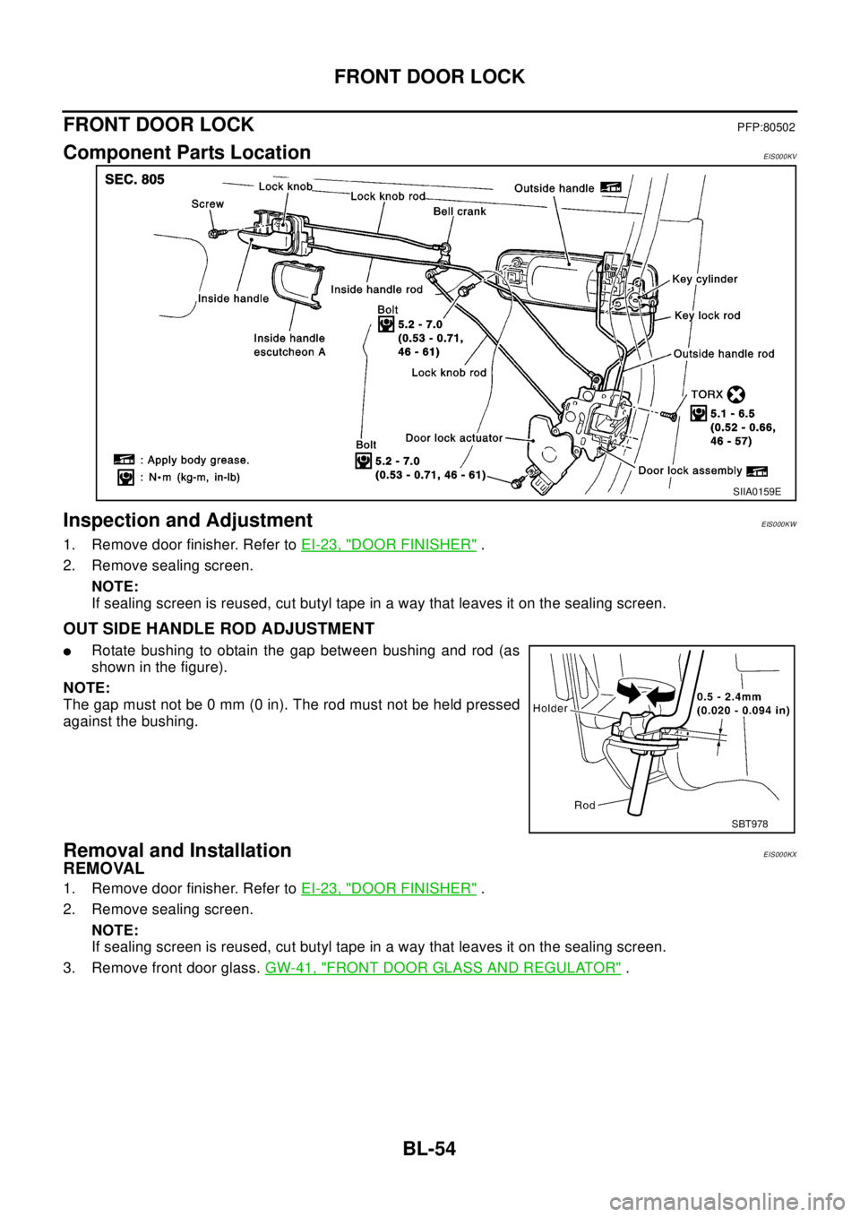
Component Parts LocationEIS000KV
Inspection and AdjustmentEIS000KW
1. Remove door finisher. Refer toEI-23, "DOOR FINISHER".
2. Remove sealing screen.
NOTE:
If sealing screen is reused, cut butyl tape in a way that leaves it on the sealing screen.
OUT SIDE HANDLE ROD ADJUSTMENT
lRotate bushing to obtain the gap between bushing and rod (as
shown in the figure).
NOTE:
The gap must not be 0 mm (0 in). The rod must not be held pressed
against the bushing.
Removal and InstallationEIS000KX
REMOVAL
1. Remove door finisher. Refer toEI-23, "DOOR FINISHER".
2. Remove sealing screen.
NOTE:
If sealing screen is reused, cut butyl tape in a way that leaves it on the sealing screen.
3. Remove front door glass.GW-41, "
FRONT DOOR GLASS AND REGULATOR".
SIIA0159E
SBT978
Page 799 of 3066
FRONT DOOR LOCK
BL-55
C
D
E
F
G
H
J
K
L
MA
B
BL
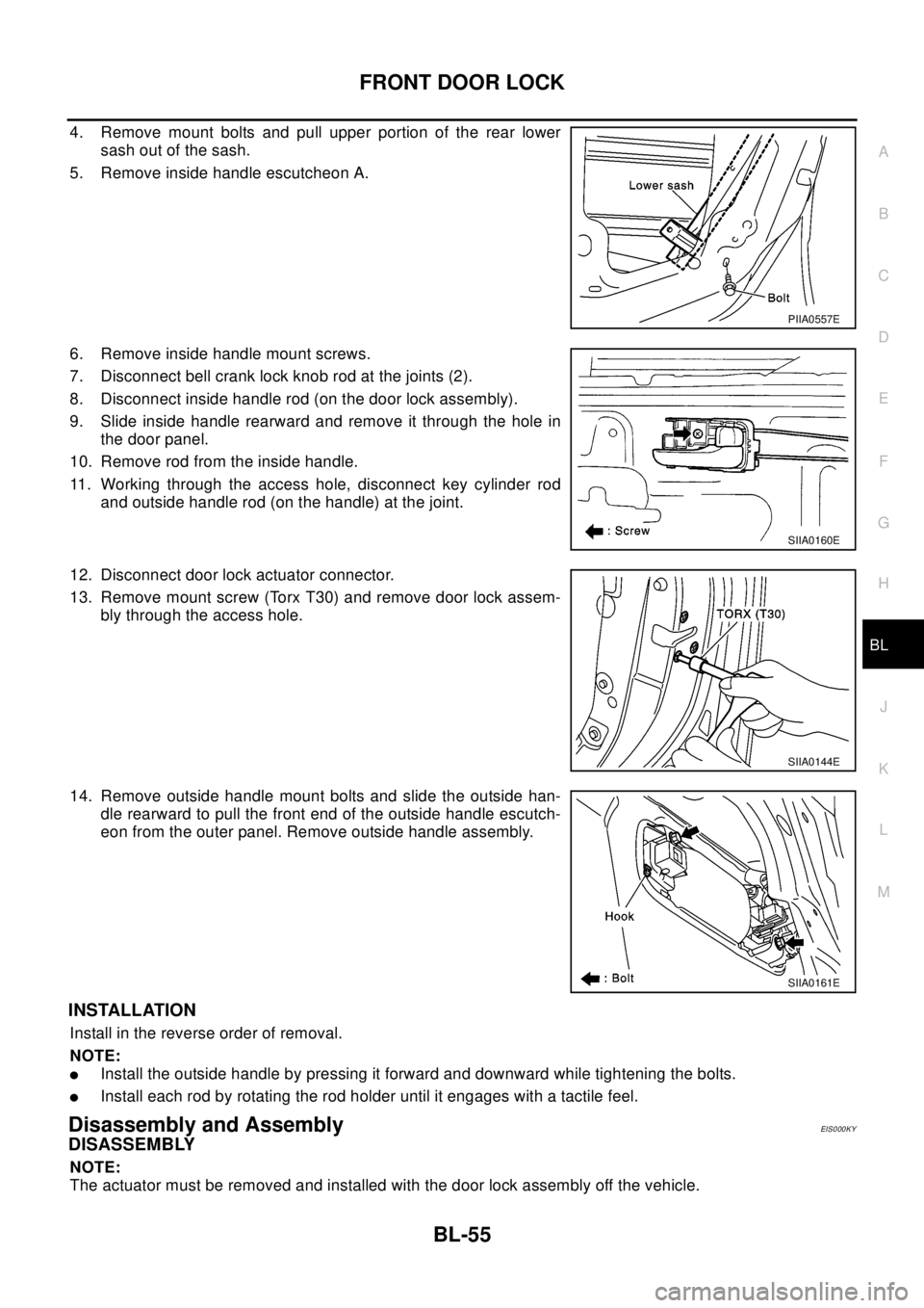
4. Remove mount bolts and pull upper portion of the rear lower
sash out of the sash.
5. Remove inside handle escutcheon A.
6. Remove inside handle mount screws.
7. Disconnect bell crank lock knob rod at the joints (2).
8. Disconnect inside handle rod (on the door lock assembly).
9. Slide inside handle rearward and remove it through the hole in
the door panel.
10. Remove rod from the inside handle.
11. Working through the access hole, disconnect key cylinder rod
and outside handle rod (on the handle) at the joint.
12. Disconnect door lock actuator connector.
13. Remove mount screw (Torx T30) and remove door lock assem-
bly through the access hole.
14. Remove outside handle mount bolts and slide the outside han-
dle rearward to pull the front end of the outside handle escutch-
eon from the outer panel. Remove outside handle assembly.
INSTALLATION
Install in the reverse order of removal.
NOTE:
lInstall the outside handle by pressing it forward and downward while tightening the bolts.
lInstall each rod by rotating the rod holder until it engages with a tactile feel.
Disassembly and AssemblyEIS000KY
DISASSEMBLY
NOTE:
The actuator must be removed and installed with the door lock assembly off the vehicle.
PIIA0557E
SIIA0160E
SIIA0144E
SIIA0161E
Page 800 of 3066
BL-56
FRONT DOOR LOCK
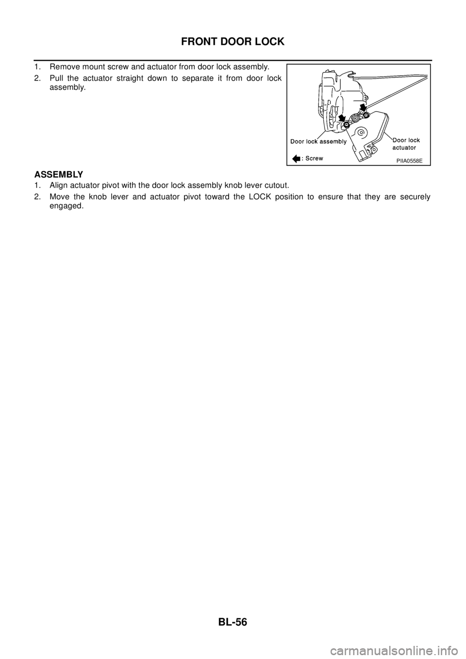
1. Remove mount screw and actuator from door lock assembly.
2. Pull the actuator straight down to separate it from door lock
assembly.
ASSEMBLY
1. Align actuator pivot with the door lock assembly knob lever cutout.
2. Move the knob lever and actuator pivot toward the LOCK position to ensure that they are securely
engaged.
PIIA0558E
Page 801 of 3066
REAR DOOR LOCK
BL-57
C
D
E
F
G
H
J
K
L
MA
B
BL
REAR DOOR LOCKPFP:82502
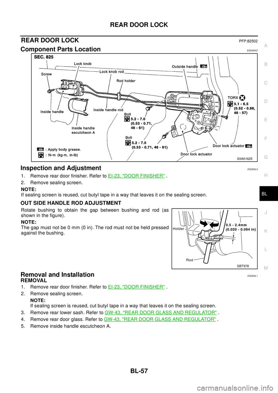
Component Parts LocationEIS000KZ
Inspection and AdjustmentEIS000L0
1. Remove rear door finisher. Refer toEI-23, "DOOR FINISHER".
2. Remove sealing screen.
NOTE:
If sealing screen is reused, cut butyl tape in a way that leaves it on the sealing screen.
OUT SIDE HANDLE ROD ADJUSTMENT
Rotate bushing to obtain the gap between bushing and rod (as
showninthefigure).
NOTE:
The gap must not be 0 mm (0 in). The rod must not be held pressed
against the bushing.
Removal and InstallationEIS000L1
REMOVAL
1. Remove rear door finisher. Refer toEI-23, "DOOR FINISHER".
2. Remove sealing screen.
NOTE:
If sealing screen is reused, cut butyl tape in a way that leaves it on the sealing screen.
3. Remove rear lower sash. Refer toGW-43, "
REAR DOOR GLASS AND REGULATOR".
4. Remove rear door glass. Refer toGW-43, "
REAR DOOR GLASS AND REGULATOR".
5. Remove inside handle escutcheon A.
SIIA0162E
SBT978
Page 802 of 3066
BL-58
REAR DOOR LOCK
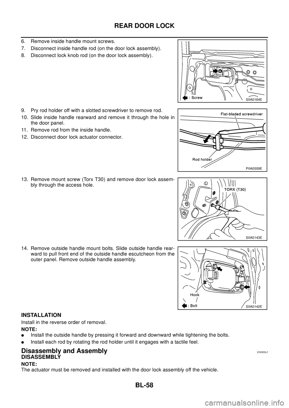
6. Remove inside handle mount screws.
7. Disconnect inside handle rod (on the door lock assembly).
8. Disconnect lock knob rod (on the door lock assembly).
9. Pry rod holder off with a slotted screwdriver to remove rod.
10. Slide inside handle rearward and remove it through the hole in
the door panel.
11. Remove rod from the inside handle.
12. Disconnect door lock actuator connector.
13. Remove mount screw (Torx T30) and remove door lock assem-
bly through the access hole.
14. Remove outside handle mount bolts. Slide outside handle rear-
ward to pull front end of the outside handle escutcheon from the
outer panel. Remove outside handle assembly.
INSTALLATION
Install in the reverse order of removal.
NOTE:
lInstall the outside handle by pressing it forward and downward while tightening the bolts.
lInstall each rod by rotating the rod holder until it engages with a tactile feel.
Disassembly and AssemblyEIS000L2
DISASSEMBLY
NOTE:
The actuator must be removed and installed with the door lock assembly off the vehicle.
SIIA0164E
PIIA0559E
SIIA0143E
SIIA0142E