belt NISSAN X-TRAIL 2003 Electronic Repair Manual
[x] Cancel search | Manufacturer: NISSAN, Model Year: 2003, Model line: X-TRAIL, Model: NISSAN X-TRAIL 2003Pages: 3066, PDF Size: 51.47 MB
Page 1 of 3066
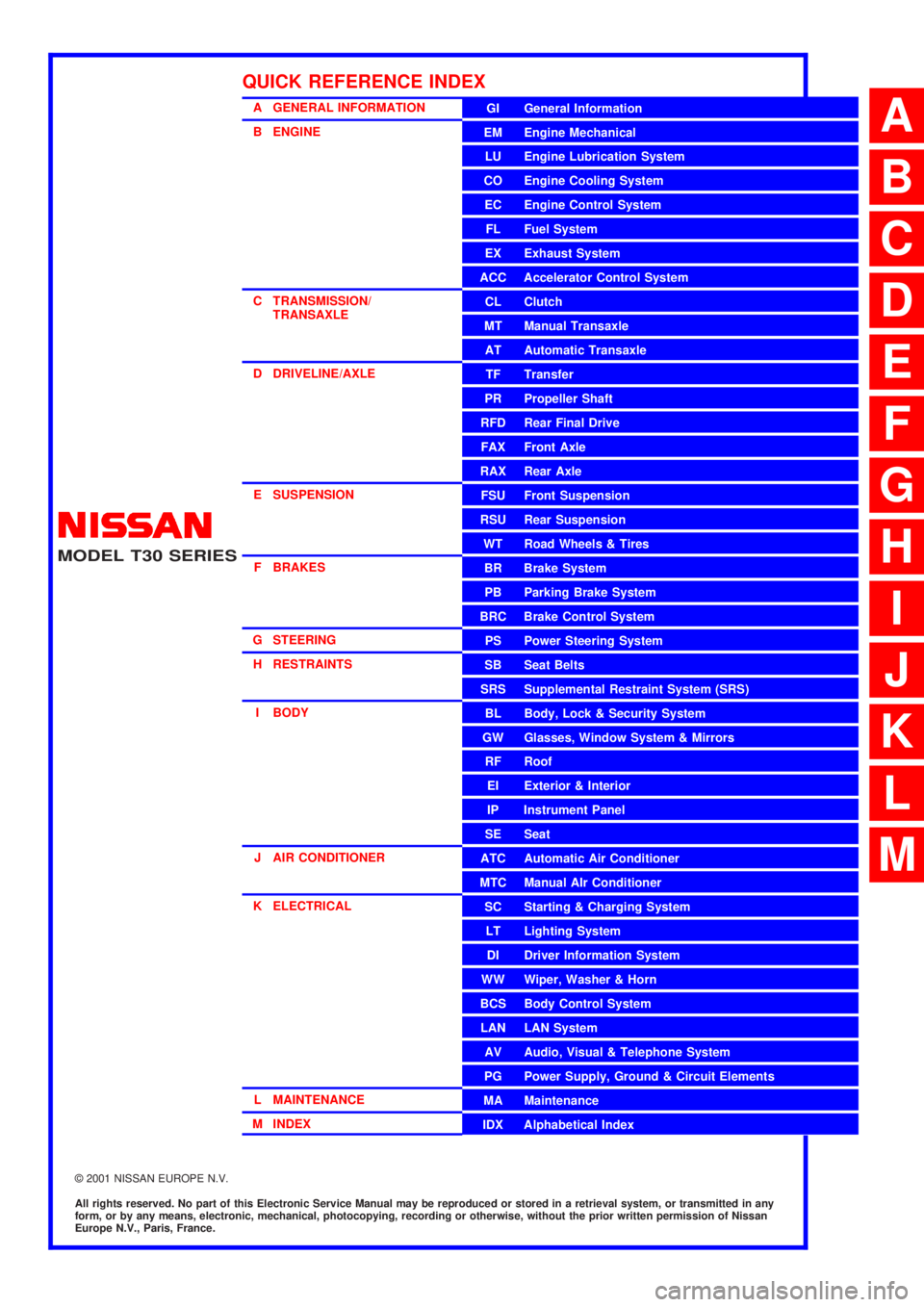
MODEL T30 SERIES
2001 NISSAN EUROPE N.V.
All rights reserved. No part of this Electronic Service Manual may be reproduced or stored in a retrieval system, or transmitted in any
form, or by any means, electronic, mechanical, photocopying, recording or otherwise, without the prior written permission of Nissan
Europe N.V., Paris, France.
A GENERAL INFORMATION
B ENGINE
C TRANSMISSION/
TRANSAXLE
D DRIVELINE/AXLE
E SUSPENSION
F BRAKES
G STEERING
H RESTRAINTS
I BODY
J AIR CONDITIONER
K ELECTRICAL
L MAINTENANCE
M INDEXGI General Information
EM Engine Mechanical
LU Engine Lubrication System
CO Engine Cooling System
EC Engine Control System
FL Fuel System
EX Exhaust System
ACC Accelerator Control System
CL Clutch
MT Manual Transaxle
AT Automatic Transaxle
TF Transfer
PR Propeller Shaft
RFD Rear Final Drive
FAX Front Axle
RAX Rear Axle
FSU Front Suspension
RSU Rear Suspension
WT Road Wheels & Tires
BR Brake System
PB Parking Brake System
BRC Brake Control System
PS Power Steering System
SB Seat Belts
SRS Supplemental Restraint System (SRS)
BL Body, Lock & Security System
GW Glasses, Window System & Mirrors
RF Roof
EI Exterior & Interior
IP Instrument Panel
SE Seat
ATC Automatic Air Conditioner
MTC Manual AIr Conditioner
SC Starting & Charging System
LT Lighting System
DI Driver Information System
WW Wiper, Washer & Horn
BCS Body Control System
LAN LAN System
AV Audio, Visual & Telephone System
PG Power Supply, Ground & Circuit Elements
MA Maintenance
IDX Alphabetical Index
QUICK REFERENCE INDEX
A
B
C
D
E
F
G
H
I
J
K
L
M
Page 7 of 3066

AT-1
AUTOMATIC TRANSAXLE
C TRANSMISSION/TRANSAXLE
CONTENTS
D
E
F
G
H
I
J
K
L
M
SECTION
A
B
AT
AUTOMATIC TRANSAXLE
PRECAUTIONS .......................................................... 5
Precautions for Supplemental Restraint System
(SRS) “AIR BAG” and “SEAT BELT PRE-TEN-
SIONER” .................................................................. 5
Precautions for On Board Diagnostic (EURO-OBD)
System of A/T and Engine — Euro-OBD — ............. 5
Precautions For Trouble Diagnosis .......................... 5
Precautions For Harness Repair .............................. 5
Precautions .............................................................. 6
Service Notice or Precautions .................................. 7
Wiring Diagrams and Trouble Diagnosis .................. 8
PREPARATION ........................................................... 9
Special Service Tools ............................................... 9
Commercial Service Tools .......................................11
A/T FLUID ................................................................. 13
Checking A/T Fluid ................................................. 13
Changing A/T Fluid ................................................ 13
OVERALL SYSTEM ................................................. 14
A/T Electrical Parts Location .................................. 14
Circuit Diagram ...................................................... 16
Cross-sectional View .............................................. 17
Hydraulic Control Circuit ........................................ 18
Shift Mechanism ..................................................... 19
Control System ....................................................... 27
Control Mechanism ................................................ 29
Control Valve .......................................................... 33
EURO-OBD
TROUBLE DIAGNOSIS — INDEX ........................... 35
Alphabetical & P No. Index for DTC ....................... 35
ON BOARD DIAGNOSTIC SYSTEM DESCRIP-
TION .......................................................................... 37
Introduction ............................................................ 37
EURO-OBD Function for A/T System .................... 37
One or Two Trip Detection Logic of EURO-OBD ... 37
EURO-OBD Diagnostic Trouble Code (DTC) ......... 37
Malfunction Indicator lamp (MIL) ............................ 41
CONSULT-II ........................................................... 41
Diagnostic Procedure Without CONSULT-II ........... 50TROUBLE DIAGNOSIS — INTRODUCTION ........... 56
Introduction ............................................................. 56
Work Flow ............................................................... 61
TROUBLE DIAGNOSIS — BASIC INSPECTION .... 64
A/T Fluid Check ...................................................... 64
Stall Test ................................................................. 65
Line Pressure Test .................................................. 68
Road Test ............................................................... 69
TROUBLE DIAGNOSIS — GENERAL DESCRIP-
TION .......................................................................... 86
Symptom Chart ....................................................... 86
TCM Terminals and Reference Value ...................125
CAN COMMUNICATION .........................................129
System Description ...............................................129
DTC P0705 PARK/NEUTRAL POSITION (PNP)
SWITCH ..................................................................130
Description ............................................................130
Wiring Diagram — AT — PNP/SW .......................132
Diagnostic Procedure ...........................................133
Component Inspection ..........................................135
DTC P0710 A/T FLUID TEMPERATURE SENSOR
CIRCUIT ..................................................................136
Description ............................................................136
Wiring Diagram — AT — FTS ..............................138
Diagnostic Procedure ...........................................139
Component Inspection ..........................................141
DTC P0720 VEHICLE SPEED SENSOR·A/T (REV-
OLUTION SENSOR) ...............................................142
Description ............................................................142
Wiring Diagram — AT — VSSA/T ........................144
Diagnostic Procedure ...........................................145
DTC P0725 ENGINESPEED SIGNAL ...................147
Description ............................................................147
Wiring Diagram — AT — ENGSS .........................148
Diagnostic Procedure ...........................................149
DTC P0731 A/T 1ST GEAR FUNCTION ................151
Description ............................................................151
Wiring Diagram — AT — 1ST ...............................154
Diagnostic Procedure ...........................................155
Component Inspection ..........................................156
Page 11 of 3066

PRECAUTIONS
AT-5
D
E
F
G
H
I
J
K
L
MA
B
AT
PRECAUTIONSPFP:00001
Precautions for Supplemental Restraint System (SRS) “AIR BAG” and “SEAT
BELT PRE-TENSIONER”
ECS004Q0
The Supplemental Restraint System such as “AIR BAG” and “SEAT BELT PRE-TENSIONER”, used along
with a front seat belt, helps to reduce the risk or severity of injury to the driver and front passenger for certain
types of collision. Information necessary to service the system safely is included in the SRS and SB section of
this Service Manual.
WA RN ING:
lTo avoid rendering the SRS inoperative, which could increase the risk of personal injury or death
in the event of a collision which would result in air bag inflation, all maintenance must be per-
formed by an authorized NISSAN/INFINITI dealer.
lImproper maintenance, including incorrect removal and installation of the SRS, can lead to per-
sonal injury caused by unintentional activation of the system. For removal of Spiral Cable and Air
Bag Module, see the SRS section.
lDo not use electrical test equipment on any circuit related to the SRS unless instructed to in this
Service Manual. SRS wiring harnesses can be identified by yellow harness connectors.
Precautions for On Board Diagnostic (EURO-OBD) System of A/T and Engine —
Euro-OBD —
ECS004Q1
The ECM has an on board diagnostic system. It will light up the malfunction indicator lamp (MIL) to warn the
driver of a malfunction causing emission deterioration.
CAUTION:
lBe sure to turn the ignition switch “OFF” and disconnect the negative battery terminal before any
repair or inspection work. The open/short circuit of related switches, sensors, solenoid valves,
etc. will cause the MIL to light up.
lBe sure to connect and lock the connectors securely after work. A loose (unlocked) connector will
cause the MIL to light up due to an open circuit. (Be sure the connector is free from water, grease,
dirt, bent terminals, etc.)
lBe sure to route and secure the harnesses properly after work. Interference of the harness with a
bracket, etc. may cause the MIL to light up due to a short circuit.
lBe sure to connect rubber tubes properly after work. A misconnected or disconnected rubber tube
may cause the MIL to light up due to a malfunction of the EGR system or fuel injection system, etc.
lBe sure to erase the unnecessary malfunction information (repairs completed) from the TCM and
ECM before returning the vehicle to the customer.
Precautions For Trouble DiagnosisECS004VN
CAN SYSTEM
lDo not apply voltage of 7.0V or higher to the measurement terminals.
lUse the tester with its open terminal voltage being 7.0V or less.
Precautions For Harness RepairECS004VO
CAN SYSTEM
lSolder the repaired parts, and wrap with tape. [Frays of twisted
line must be within 110 mm (4.33 in)]
PKIA0306E
Page 466 of 3066
![NISSAN X-TRAIL 2003 Electronic Repair Manual AT-460
[ALL]
REMOVAL AND INSTALLATION
3. Install torque converter to drive plate.
lWith converter installed, rotate crankshaft several turns
to check that transaxle rotates freely without binding.
4. NISSAN X-TRAIL 2003 Electronic Repair Manual AT-460
[ALL]
REMOVAL AND INSTALLATION
3. Install torque converter to drive plate.
lWith converter installed, rotate crankshaft several turns
to check that transaxle rotates freely without binding.
4.](/img/5/57402/w960_57402-465.png)
AT-460
[ALL]
REMOVAL AND INSTALLATION
3. Install torque converter to drive plate.
lWith converter installed, rotate crankshaft several turns
to check that transaxle rotates freely without binding.
4. Tighten belts fixing transaxle.
5. Reinstall any part removed.
6. Adjust control cable. Refer toAT-456, "
Control Cable Adjust-
ment".
7. Check continuity of PNP switch. Refer toAT-130, "
DTC P0705
PARK/NEUTRAL POSITION (PNP) SWITCH".
8. Refill transaxle with ATF and check fluid level.
9. Move selector lever through all positions to be sure that tran-
saxle operates correctly. With parking brake applied, idle
engine. Move selector lever through “N” to “D”, to “2”, to “1” and
“R” positions. A slight shock should be felt through the hand
gripping the selector each time the transaxle is shifted.
10. Perform road test. Refer toAT-69, "
Road Test".
AAT266A
Bolt No.Tightening torque
N-m (kg-m, ft-lb)Bolt length “ L ”
mm (in)
1
69.6 - 79.4 (7.1 - 8.1, 51.4 - 58.6)49 (1.93)
245(1.77)
3
39.2 - 46.1 (4.0 - 4.7, 29.0 - 34.0)40 (1.57)
430(1.18)
5
30.4 - 40.2 (3.1 - 4.1, 22.4 - 29.7)40 (1.57)
645(1.97)
SCIA0795E
SAT638A
Page 579 of 3066
ATC-1
AUTOMATIC AIR CONDITIONER
J AIR CONDITIONER
CONTENTS
C
D
E
F
G
H
I
K
L
M
SECTION
A
B
AT C
AUTOMATIC AIR CONDITIONER
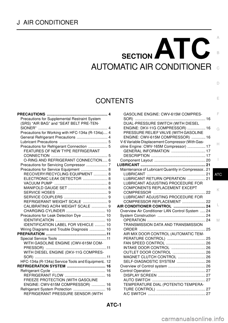
PRECAUTIONS .......................................................... 4
Precautions for Supplemental Restraint System
(SRS) “AIR BAG” and “SEAT BELT PRE-TEN-
SIONER” .................................................................. 4
Precautions for Working with HFC-134a (R-134a)..... 4
General Refrigerant Precautions .............................. 4
Lubricant Precautions .............................................. 5
Precautions for Refrigerant Connection ................... 5
FEATURES OF NEW TYPE REFRIGERANT
CONNECTION ...................................................... 5
O-RING AND REFRIGERANT CONNECTION..... 6
Precautions for Servicing Compressor ..................... 7
Precautions for Service Equipment .......................... 8
RECOVERY/RECYCLING EQUIPMENT .............. 8
ELECTRONIC LEAK DETECTOR ........................ 8
VACUUM PUMP ................................................... 8
MANIFOLD GAUGE SET ...................................... 8
SERVICE HOSES ................................................. 9
SERVICE COUPLERS .......................................... 9
REFRIGERANT WEIGHT SCALE ........................ 9
CALIBRATING ACR4 WEIGHT SCALE ................ 9
CHARGING CYLINDER ...................................... 10
Precautions for Leak Detection Dye ....................... 10
IDENTIFICATION ................................................ 10
IDENTIFICATION LABEL FOR VEHICLE ........... 10
Wiring Diagrams and Trouble Diagnosis ................ 10
PREPARATION ..........................................................11
Special Service Tools ..............................................11
WITH GASOLINE ENGINE (CWV-615M COM-
PRESSOR) ..........................................................11
WITH DIESEL ENGINE (DKV-11G COMPRES-
SOR) ....................................................................11
HFC-134a (R-134a) Service Tools and Equipment... 12
REFRIGERATION SYSTEM ..................................... 16
Refrigerant Cycle ................................................... 16
REFRIGERANT FLOW ....................................... 16
FREEZE PROTECTION (WITH GASOLINE
ENGINE: CWV-615M COMPRESSOR) .............. 16
Refrigerant System Protection ............................... 16
REFRIGERANT PRESSURE SENSOR (WITHGASOLINE ENGINE: CWV-615M COMPRES-
SOR) ................................................................... 16
DUAL-PRESSURE SWITCH (WITH DIESEL
ENGINE: DKV-11G COMPRESSOR) .................. 16
PRESSURE RELIEF VALVE (WITH GASOLINE
ENGINE: CWV-615M COMPRESSOR) .............. 16
V-6 Variable Displacement Compressor (With Gas-
oline Engine: CWV-165M Compressor) .................. 17
GENERAL INFORMATION ................................. 17
DESCRIPTION .................................................... 17
Component Layout ................................................. 20
LUBRICANT .............................................................. 21
Maintenance of Lubricant Quantity in Compressor... 21
LUBRICANT ........................................................ 21
LUBRICANT RETURN OPERATION .................. 21
LUBRICANT ADJUSTING PROCEDURE FOR
COMPONENTS REPLACEMENT EXCEPT
COMPRESSOR .................................................. 22
LUBRICANT ADJUSTING PROCEDURE FOR
COMPRESSOR REPLACEMENT ....................... 22
AIR CONDITIONER CONTROL ............................... 24
Overview Air Conditioner LAN Control System ...... 24
System Construction .............................................. 24
OPERATION ........................................................ 24
TRANSMISSION DATA AND TRANSMISSION
ORDER ............................................................... 25
AIR MIX DOOR CONTROL (AUTOMATIC TEM-
PERATURE CONTROL) ..................................... 25
FAN SPEED CONTROL ...................................... 26
INTAKE DOOR CONTROL ................................. 26
OUTLET DOOR CONTROL ................................ 26
MAGNET CLUTCH CONTROL ........................... 26
SELF-DIAGNOSTIC SYSTEM ............................ 26
Overview of Control system .................................... 26
Control Operation ................................................... 27
DISPLAY SCREEN .............................................. 27
AUTO SWITCH ................................................... 27
TEMPERATURE DIAL (POTENTIO TEMPERA-
TURE CONTROL) ............................................... 27
A/C SWITCH ....................................................... 27
Page 581 of 3066

ATC-3
C
D
E
F
G
H
I
K
L
MA
B
AT C INTAKE SENSOR CIRCUIT ................................... 108
Removal and Installation ...................................... 108
BLOWER UNIT ....................................................... 109
Removal and Installation ...................................... 109
REMOVAL ......................................................... 109
INSTALLATION ................................................. 109
Disassembly and Assembly ................................. 109
BLOWER MOTOR ................................................... 111
Removal and Installation ...................................... . 111
INTAKE DOOR MOTOR .......................................... 112
Removal and Installation ....................................... 112
FAN CONTROL AMPLIFIER ................................... 113
Removal and Installation ....................................... 113
VENTILATION AIR FILTER ..................................... 114
Removal and Installation ....................................... 114
Function ................................................................ 114
Replacement Timing ............................................. 114
Replacement Procedures ...................................... 114
HEATER & COOLING UNIT ASSEMBLY ............... 115
Removal and Installation ....................................... 115
REMOVAL .......................................................... 115
INSTALLATION .................................................. 116
Disassembly and Assembly .................................. 116
MODE DOOR MOTOR ............................................ 118
Removal and Installation ....................................... 118
AIR MIX DOOR MOTOR .......................................... 119
Removal and Installation ....................................... 119
HEATER CORE ...................................................... 120
Removal and Installation ...................................... 120
DUCTS AND GRILLES .......................................... 121
Removal and Installation ...................................... 121
Ventilator Duct, Defroster Nozzle and Defroster
Ducts .................................................................... 121
Center Ventilator Grille ......................................... 121
Side Ventilator Grille ............................................. 121
Foot Duct .............................................................. 122
Floor duct ............................................................. 122
REFRIGERANT LINES ........................................... 123
HFC-134a (R-134a) Service Procedure ............... 123
SETTING OF SERVICE TOOLS AND EQUIP-
MENT ................................................................ 123
Components ......................................................... 125
Removal and Installation for Compressor ............ 126REMOVAL .........................................................126
INSTALLATION .................................................128
Removal and Installation for Compressor Clutch . 129
REMOVAL .........................................................129
INSTALLATION .................................................132
Removal and Installation for Low-pressure flexible
hose ......................................................................135
REMOVAL .........................................................135
INSTALLATION .................................................136
Removal and Installation for High-pressure flexible
hose ......................................................................136
REMOVAL .........................................................136
INSTALLATION .................................................136
Removal and Installation for High-pressure pipe ..137
REMOVAL .........................................................137
INSTALLATION .................................................137
Removal and Installation for Refrigerant Pressure
Sensor ..................................................................137
Removal and Installation for Dual-pressure Switch.138
Removal and Installation for Condenser ..............138
REMOVAL .........................................................138
INSTALLATION .................................................138
Removal and Installation for Evaporator ..............139
REMOVAL .........................................................139
INSTALLATION .................................................139
Removal and Installation for Expansion Valve ......140
Removal and Installation for Desiccant Assembly. 140
REMOVAL .........................................................140
INSTALLATION .................................................140
Checking for Refrigerant Leaks ............................140
Checking System for Leaks Using the Fluorescent
Leak Detector .......................................................141
Dye Injection .........................................................141
Electronic Refrigerant Leak Detector ....................141
PRECAUTIONS FOR HANDLING LEAK
DETECTOR .......................................................141
CHECKING PROCEDURE ...............................142
Service Data and Specifications (SDS) ................143
COMPRESSOR ................................................143
LUBRICANT ......................................................144
REFRIGERANT .................................................144
ENGINE IDLING SPEED ..................................144
BELT TENSION .................................................144
Page 582 of 3066
ATC-4
PRECAUTIONS
PRECAUTIONS
PFP:00001
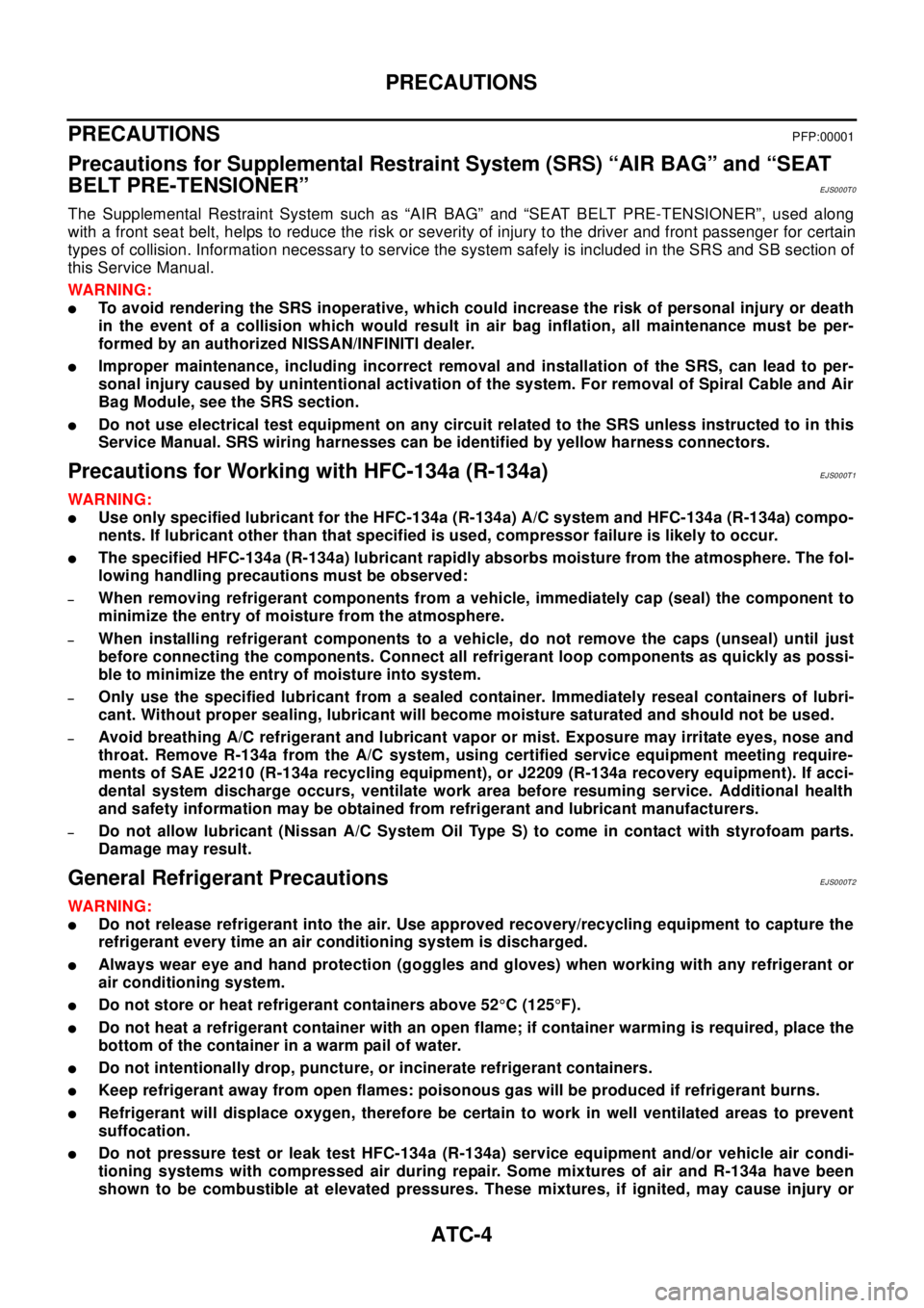
Precautions for Supplemental Restraint System (SRS) “AIR BAG” and “SEAT
BELT PRE-TENSIONER”
EJS000T0
The Supplemental Restraint System such as “AIR BAG” and “SEAT BELT PRE-TENSIONER”, used along
with a front seat belt, helps to reduce the risk or severity of injury to the driver and front passenger for certain
types of collision. Information necessary to service the system safely is included in the SRS and SB section of
this Service Manual.
WAR NIN G:
lTo avoid rendering the SRS inoperative, which could increase the risk of personal injury or death
in the event of a collision which would result in air bag inflation, all maintenance must be per-
formed by an authorized NISSAN/INFINITI dealer.
lImproper maintenance, including incorrect removal and installation of the SRS, can lead to per-
sonal injury caused by unintentional activation of the system. For removal of Spiral Cable and Air
Bag Module, see the SRS section.
lDo not use electrical test equipment on any circuit related to the SRS unless instructed to in this
Service Manual. SRS wiring harnesses can be identified by yellow harness connectors.
Precautions for Working with HFC-134a (R-134a)EJS000T1
WAR NIN G:
lUse only specified lubricant for the HFC-134a (R-134a) A/C system and HFC-134a (R-134a) compo-
nents. If lubricant other than that specified is used, compressor failure is likely to occur.
lThe specified HFC-134a (R-134a) lubricant rapidly absorbs moisture from the atmosphere. The fol-
lowing handling precautions must be observed:
–When removing refrigerant components from a vehicle, immediately cap (seal) the component to
minimize the entry of moisture from the atmosphere.
–When installing refrigerant components to a vehicle, do not remove the caps (unseal) until just
before connecting the components. Connect all refrigerant loop components as quickly as possi-
bletominimizetheentryofmoistureintosystem.
–Only use the specified lubricant from a sealed container. Immediately reseal containers of lubri-
cant. Without proper sealing, lubricant will become moisture saturated and should not be used.
–Avoid breathing A/C refrigerant and lubricant vapor or mist. Exposure may irritate eyes, nose and
throat. Remove R-134a from the A/C system, using certified service equipment meeting require-
ments of SAE J2210 (R-134a recycling equipment), or J2209 (R-134a recovery equipment). If acci-
dental system discharge occurs, ventilate work area before resuming service. Additional health
and safety information may be obtained from refrigerant and lubricant manufacturers.
–Do not allow lubricant (Nissan A/C System Oil Type S) to come in contact with styrofoam parts.
Damage may result.
General Refrigerant PrecautionsEJS000T2
WAR NIN G:
lDo not release refrigerant into the air. Use approved recovery/recycling equipment to capture the
refrigerant every time an air conditioning system is discharged.
lAlways wear eye and hand protection (goggles and gloves) when working with any refrigerant or
air conditioning system.
lDo not store or heat refrigerant containers above 52°C(125°F).
lDo not heat a refrigerant container with an open flame; if container warming is required, place the
bottom of the container in a warm pail of water.
lDo not intentionally drop, puncture, or incinerate refrigerant containers.
lKeep refrigerant away from open flames: poisonous gas will be produced if refrigerant burns.
lRefrigerant will displace oxygen, therefore be certain to work in well ventilated areas to prevent
suffocation.
lDo not pressure test or leak test HFC-134a (R-134a) service equipment and/or vehicle air condi-
tioning systems with compressed air during repair. Some mixtures of air and R-134a have been
shown to be combustible at elevated pressures. These mixtures, if ignited, may cause injury or
Page 660 of 3066
ATC-82
TROUBLE DIAGNOSIS
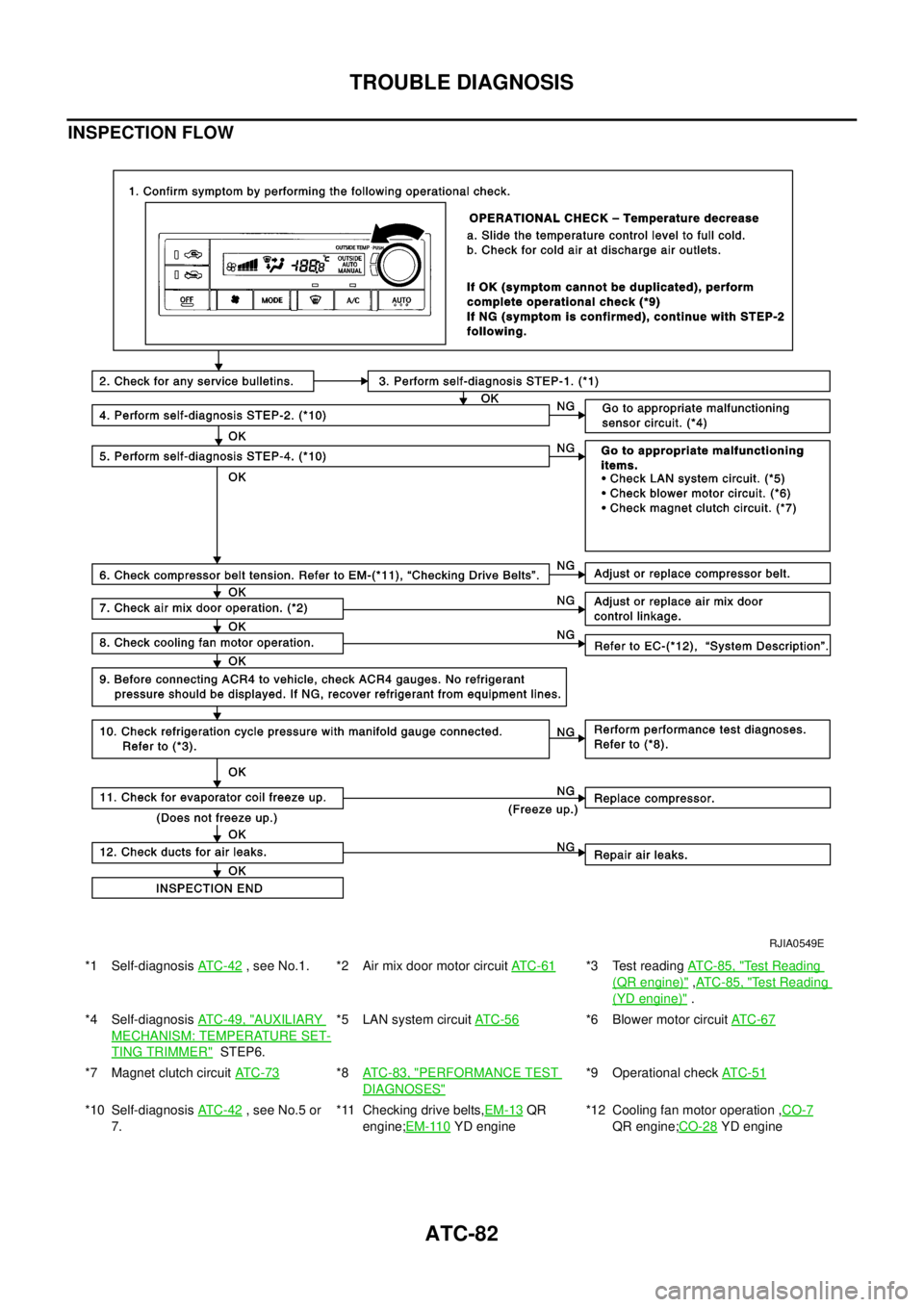
INSPECTION FLOW
*1 Self-diagnosisAT C - 4 2, see No.1. *2 Air mix door motor circuitAT C - 6 1*3 Test readingAT C - 8 5 , "Te s t R e a d i n g
(QR engine)",AT C - 8 5 , "Test Reading
(YD engine)".
*4 Self-diagnosisAT C - 4 9 , "
AUXILIARY
MECHANISM: TEMPERATURE SET-
TING TRIMMER"STEP6.*5 LAN system circuitAT C -5 6
*6 Blower motor circuitAT C -6 7
*7 Magnet clutch circuitAT C - 7 3*8AT C - 8 3 , "PERFORMANCE TEST
DIAGNOSES"
*9 Operational checkAT C - 5 1
*10 Self-diagnosisAT C - 4 2, see No.5 or
7.*11 Checking drive belts,EM-13QR
engine;EM-110
YD engine*12 Cooling fan motor operation ,CO-7QR engine;CO-28YD engine
RJIA0549E
Page 662 of 3066
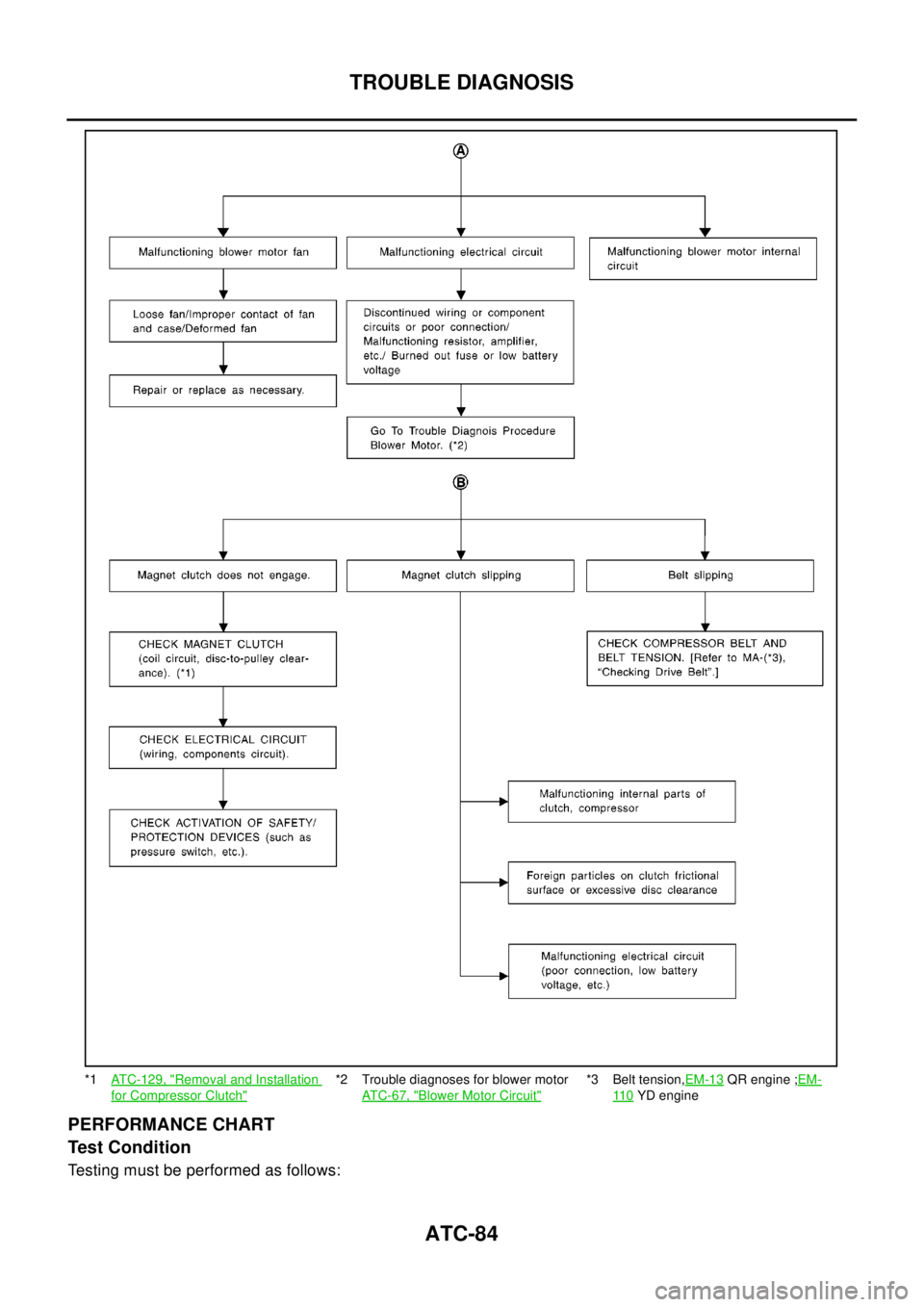
ATC-84
TROUBLE DIAGNOSIS
PERFORMANCE CHART
Test Condition
Testing must be performed as follows:
*1ATC-129, "Removal and Installation
for Compressor Clutch"
*2 Trouble diagnoses for blower motor
AT C - 6 7 , "
Blower Motor Circuit"
*3 Belt tension,EM-13QR engine ;EM-
11 0YD engine
Page 670 of 3066
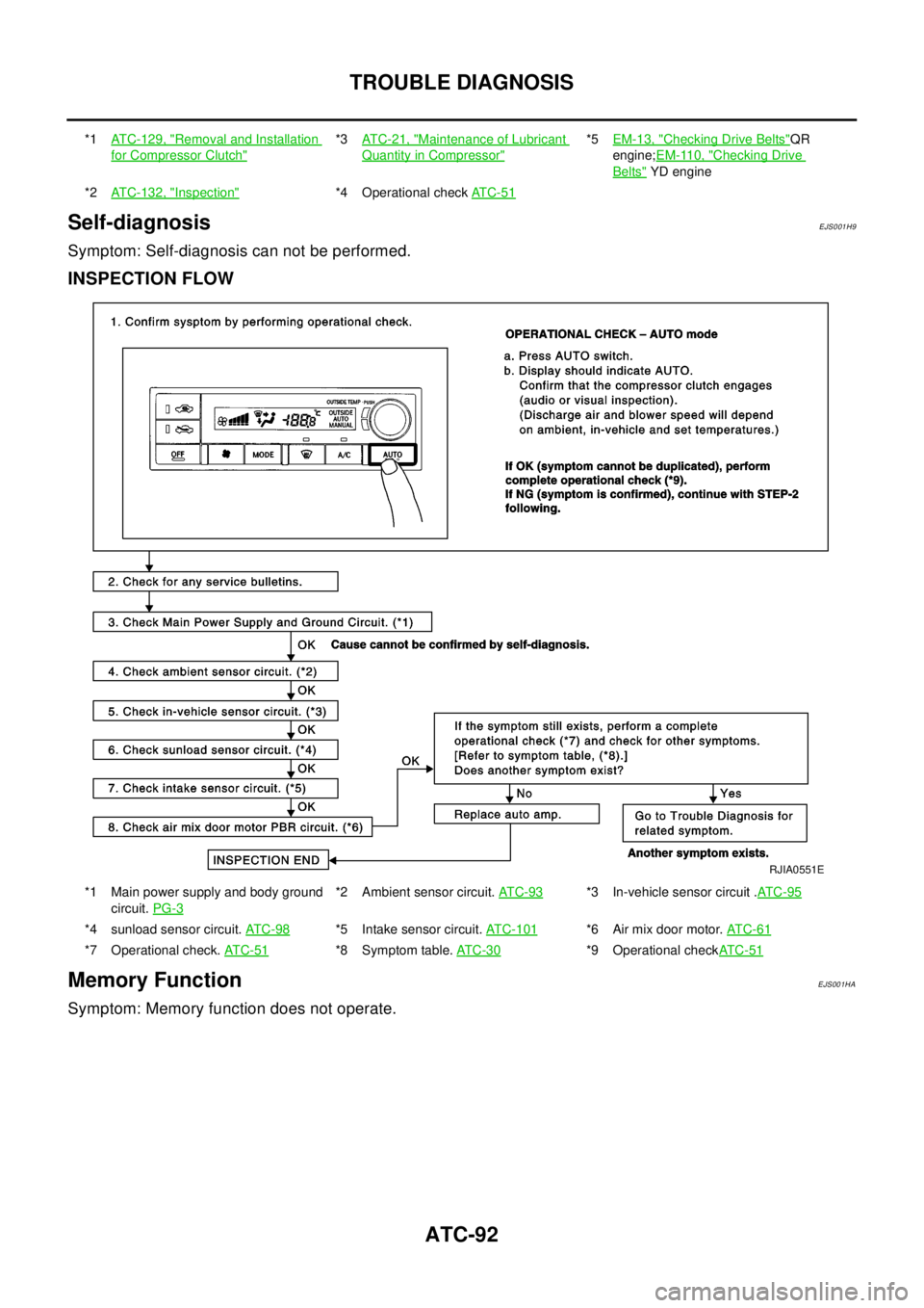
ATC-92
TROUBLE DIAGNOSIS
Self-diagnosis
EJS001H9
Symptom: Self-diagnosis can not be performed.
INSPECTION FLOW
Memory FunctionEJS001HA
Symptom: Memory function does not operate.
*1ATC-129, "Removal and Installation
for Compressor Clutch"
*3AT C - 2 1 , "Maintenance of Lubricant
Quantity in Compressor"
*5EM-13, "Checking Drive Belts"QR
engine;EM-110, "
Checking Drive
Belts"YD engine
*2ATC-132, "
Inspection"*4 Operational checkAT C - 5 1
*1 Main power supply and body ground
circuit.PG-3*2 Ambient sensor circuit.AT C - 9 3*3 In-vehicle sensor circuit .AT C - 9 5
*4 sunload sensor circuit.AT C - 9 8*5 Intake sensor circuit.AT C - 1 0 1*6 Air mix door motor.AT C - 6 1
*7 Operational check.AT C - 5 1*8 Symptom table.AT C -3 0*9 Operational checkAT C - 5 1
RJIA0551E