mileage NISSAN X-TRAIL 2003 Electronic Repair Manual
[x] Cancel search | Manufacturer: NISSAN, Model Year: 2003, Model line: X-TRAIL, Model: NISSAN X-TRAIL 2003Pages: 3066, PDF Size: 51.47 MB
Page 14 of 3066

AT-8
PRECAUTIONS
lVehicle has TCC shudder and/or no TCC apply. Replace only after all hydraulic and electrical diagnoses
have been made. (Converter clutch material may be glazed.)
lConverter is contaminated with engine coolant containing antifreeze.
lInternal failure of stator roller clutch.
lHeavy clutch debris due to overheating (blue converter).
lSteel particles or clutch lining material found in fluid filter or on magnet when no internal parts in unit are
worn or damaged — indicates that lining material came from converter.
The torque converter should not be replaced if:
lThe fluid has an odor, is discolored, and there is no evidence of metal or clutch facing particles.
lThe threads in one or more of the converter bolt holes are damaged.
lTransaxle failure did not display evidence of damaged or worn internal parts, steel particles or clutch plate
lining material in unit and inside the fluid filter.
lVehicle has been exposed to high mileage (only). The exception may be where the torque converter
clutch dampener plate lining has seen excess wear by vehicles operated in heavy and/or constant traffic,
such as taxi, delivery or police use.
EURO-OBD SELF-DIAGNOSIS — EURO-OBD —
lA/T self-diagnosis is performed by the TCM in combination with the ECM. The results can be read through
the blinking pattern of the O/D OFF indicator lamp or the malfunction indicator lamp (MIL). Refer to the
table onAT-42, "
SELF-DIAGNOSTIC RESULT TEST MODE"for the indicator used to display each self-
diagnostic result.
lThe self-diagnostic results indicated by the MIL are automatically stored in both the ECM and TCM mem-
ories.
Always perform the procedure “HOW TO ERASE DTC” onAT-39, "
HOW TO ERASE DTC"to com-
plete the repair and avoid unnecessary blinking of the MIL.
lThe following self-diagnostic items can be detected using ECM self-diagnostic results mode* only when
the O/D OFF indicator lamp does not indicate any malfunctions.
–PNP switch
–A/T 1st, 2nd, 3rd, or 4th gear function
*: For details of EURO-OBD, refer toAT - 3 7 , "
ON BOARD DIAGNOSTIC SYSTEM DESCRIPTION".
lCertain systems and components, especially those related to EURO-OBD, may use a new style
slide-locking type harness connector.
For description and how to disconnect, refer toPG-70, "
HARNESS CONNECTOR".
Wiring Diagrams and Trouble DiagnosisECS004Q4
When you read wiring diagrams, refer to the following:
lGI-14, "How to Read Wiring Diagrams".
lPG-2, "POWER SUPPLY ROUTING".
When you perform trouble diagnosis, refer to the following:
lGI-11, "HOW TO FOLLOW TEST GROUPS IN TROUBLE DIAGNOSES".
l"", “HOW TO PERFORM EFFICIENT DIAGNOSIS FOR AN ELECTRICAL INCIDENT”
Page 63 of 3066
![NISSAN X-TRAIL 2003 Electronic Repair Manual TROUBLE DIAGNOSIS — INTRODUCTION
AT-57
[EURO-OBD]
D
E
F
G
H
I
J
K
L
MA
B
AT
DIAGNOSTIC WORKSHEET
Information from Customer
KEY POINTS
lWHAT..... Vehicle & A/T model
lWHEN..... Date, Frequencies
lWHE NISSAN X-TRAIL 2003 Electronic Repair Manual TROUBLE DIAGNOSIS — INTRODUCTION
AT-57
[EURO-OBD]
D
E
F
G
H
I
J
K
L
MA
B
AT
DIAGNOSTIC WORKSHEET
Information from Customer
KEY POINTS
lWHAT..... Vehicle & A/T model
lWHEN..... Date, Frequencies
lWHE](/img/5/57402/w960_57402-62.png)
TROUBLE DIAGNOSIS — INTRODUCTION
AT-57
[EURO-OBD]
D
E
F
G
H
I
J
K
L
MA
B
AT
DIAGNOSTIC WORKSHEET
Information from Customer
KEY POINTS
lWHAT..... Vehicle & A/T model
lWHEN..... Date, Frequencies
lWHERE..... Road conditions
lHOW..... Operating conditions, Symptoms
Customer name MR/MS Model & Year VIN
Trans. model Engine Mileage
Incident Date Manuf. Date In Service Date
FrequencyoContinuousoIntermittent ( times a day)
SymptomsoVehicle does not move. (oAny positionoParticular position)
oNo up-shift (o1st®2ndo2nd®3rdo3rd®O/D)
oNo down-shift (oO/D®3rdo3rd®2ndo2nd®1st)
oLockup malfunction
oShift point too high or too low.
oShift shock or slip (oN®DoLockupoAny drive position)
oNoise or vibration
oNo kickdown
oNo pattern select
oOthers
()
O/D OFF indicator lamp Blinks for about 8 seconds.
oContinuously litoNot lit
Malfunction indicator lamp (MIL)oContinuously litoNot lit
Page 286 of 3066
![NISSAN X-TRAIL 2003 Electronic Repair Manual AT-280
[EXC.F/EURO-OBD]
TROUBLE DIAGNOSIS — INTRODUCTION
DIAGNOSTIC WORKSHEET
Information from Customer
KEY POINTS
lWHAT..... Vehicle & A/T model
lWHEN..... Date, Frequencies
lWHERE..... Road condit NISSAN X-TRAIL 2003 Electronic Repair Manual AT-280
[EXC.F/EURO-OBD]
TROUBLE DIAGNOSIS — INTRODUCTION
DIAGNOSTIC WORKSHEET
Information from Customer
KEY POINTS
lWHAT..... Vehicle & A/T model
lWHEN..... Date, Frequencies
lWHERE..... Road condit](/img/5/57402/w960_57402-285.png)
AT-280
[EXC.F/EURO-OBD]
TROUBLE DIAGNOSIS — INTRODUCTION
DIAGNOSTIC WORKSHEET
Information from Customer
KEY POINTS
lWHAT..... Vehicle & A/T model
lWHEN..... Date, Frequencies
lWHERE..... Road conditions
lHOW..... Operating conditions, Symptoms
Customer name MR/MS Model & Year VIN
Trans. model Engine Mileage
Incident Date Manuf. Date In Service Date
FrequencyoContinuousoIntermittent ( times a day)
SymptomsoVehicle does not move. (oAny positionoParticular position)
oNo up-shift (o1st®2ndo2nd®3rdo3rd®O/D)
oNo down-shift (oO/D®3rdo3rd®2ndo2nd®1st)
oLockup malfunction
oShift point too high or too low.
oShift shock or slip (oN®DoLockupoAny drive position)
oNoise or vibration
oNo kickdown
oNo pattern select
oOthers
()
O/D OFF indicator lamp Blinks for about 8 seconds.
oContinuously litoNot lit
Page 844 of 3066
BR-10
BRAKE FLUID
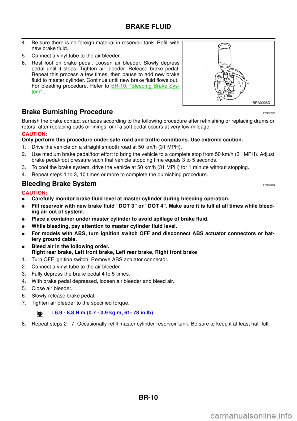
4. Be sure there is no foreign material in reservoir tank. Refill with
new brake fluid.
5. Connect a vinyl tube to the air bleeder.
6. Rest foot on brake pedal. Loosen air bleeder. Slowly depress
pedal until it stops. Tighten air bleeder. Release brake pedal.
Repeat this process a few times, then pause to add new brake
fluid to master cylinder. Continue until new brake fluid flows out.
For bleeding procedure. Refer toBR-10, "
Bleeding Brake Sys-
tem".
Brake Burnishing ProcedureEFS001C8
Burnish the brake contact surfaces according to the following procedure after refinishing or replacing drums or
rotors, after replacing pads or linings, or if a soft pedal occurs at very low mileage.
CAUTION:
Only perform this procedure under safe road and traffic conditions. Use extreme caution.
1. Drive the vehicle on a straight smooth road at 50 km/h (31 MPH).
2. Use medium brake pedal/foot effort to bring the vehicle to a complete stop from 50 km/h (31 MPH). Adjust
brake pedal/foot pressure such that vehicle stopping time equals 3 to 5 seconds.
3. To cool the brake system, drive the vehicle at 50 km/h (31 MPH) for 1 minute without stopping.
4. Repeat steps 1 to 3, 10 times or more to complete the burnishing procedure.
Bleeding Brake SystemEFS000C4
CAUTION:
lCarefully monitor brake fluid level at master cylinder during bleeding operation.
lFill reservoir with new brake fluid “DOT 3” or “DOT 4”. Make sure it is full at all times while bleed-
ing air out of system.
lPlace a container under master cylinder to avoid spillage of brake fluid.
lWhile bleeding, pay attention to master cylinder fluid level.
lFor models with ABS, turn ignition switch OFF and disconnect ABS actuator connectors or bat-
tery ground cable.
lBleed air in the following order.
Right rear brake, Left front brake, Left rear brake, Right front brake
1. Turn OFF ignition switch. Remove ABS actuator connector.
2. Connect a vinyl tube to the air bleeder.
3. Fully depress the brake pedal 4 to 5 times.
4. With brake pedal depressed, loosen air bleeder and bleed air.
5. Close air bleeder.
6. Slowly release brake pedal.
7. Tighten air bleeder to the specified torque.
8. Repeat steps 2 - 7. Occasionally refill master cylinder reservoir tank. Be sure to keep it at least half-full.
BRA0006D
: 6.9 - 8.8 N·m (0.7 - 0.9 kg·m, 61- 78 in·lb)
Page 855 of 3066
FRONT DISC BRAKE
BR-21
C
D
E
G
H
I
J
K
L
MA
B
BR
FRONT DISC BRAKEPFP:41000
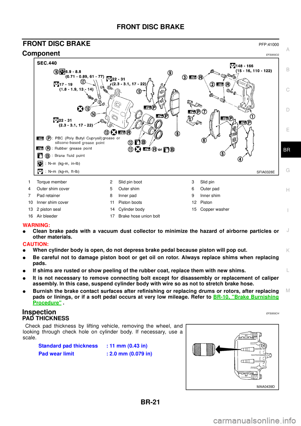
ComponentEFS000CG
WA RN ING:
lClean brake pads with a vacuum dust collector to minimize the hazard of airborne particles or
other materials.
CAUTION:
lWhen cylinder body is open, do not depress brake pedal because piston will pop out.
lBe careful not to damage piston boot or get oil on rotor. Always replace shims when replacing
pads.
lIf shims are rusted or show peeling of the rubber coat, replace them with new shims.
lIt is not necessary to remove connecting bolt except for disassembly or replacement of caliper
assembly. In this case, suspend cylinder body with wire so as not to stretch brake hose.
lBurnish the brake contact surfaces after refinishing or replacing drums or rotors, after replacing
pads or linings, or if a soft pedal occurs at very low mileage. Refer toBR-10, "
Brake Burnishing
Procedure".
InspectionEFS000CH
PAD THICKNESS
Check pad thickness by lifting vehicle, removing the wheel, and
looking through check hole on cylinder body. If necessary, use a
scale.
SFIA0328E
1 Torque member 2 Slid pin boot 3 Slid pin
4 Outer shim cover 5 Outer shim 6 Outer pad
7 Pad retainer 8 Inner pad 9 Inner shim
10 Inner shim cover 11 Piston boots 12 Piston
13 2 piston seal 14 Cylinder body 15 Copper washer
16 Air bleeder 17 Brake hose union bolt
Standard pad thickness : 11 mm (0.43 in)
Pad wear limit : 2.0 mm (0.079 in)
MAA0439D
Page 859 of 3066
FRONT DISC BRAKE
BR-25
C
D
E
G
H
I
J
K
L
MA
B
BR
Thickness Inspection
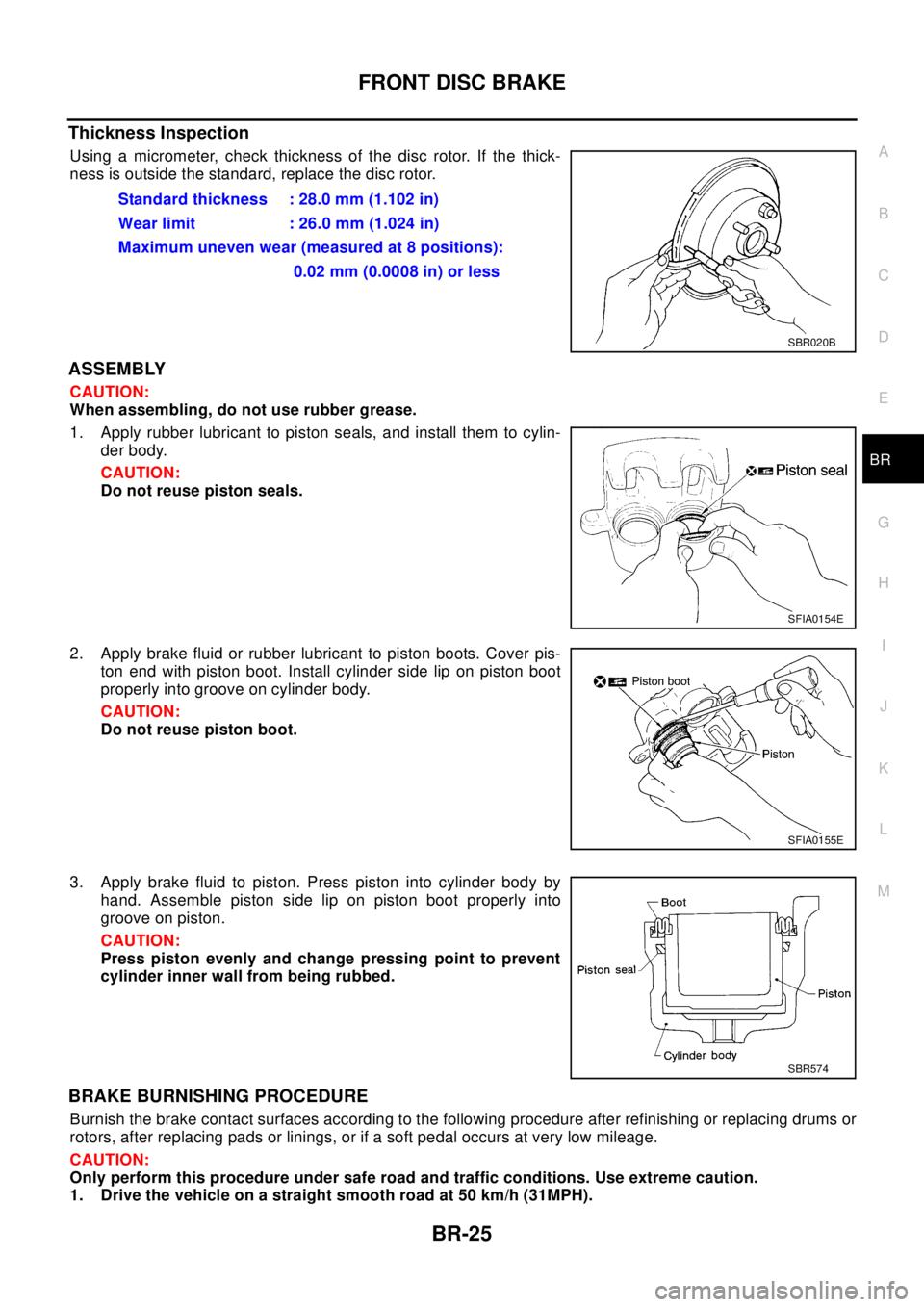
Using a micrometer, check thickness of the disc rotor. If the thick-
ness is outside the standard, replace the disc rotor.
ASSEMBLY
CAUTION:
When assembling, do not use rubber grease.
1. Apply rubber lubricant to piston seals, and install them to cylin-
der body.
CAUTION:
Do not reuse piston seals.
2. Apply brake fluid or rubber lubricant to piston boots. Cover pis-
ton end with piston boot. Install cylinder side lip on piston boot
properly into groove on cylinder body.
CAUTION:
Do not reuse piston boot.
3. Apply brake fluid to piston. Press piston into cylinder body by
hand. Assemble piston side lip on piston boot properly into
groove on piston.
CAUTION:
Press piston evenly and change pressing point to prevent
cylinder inner wall from being rubbed.
BRAKE BURNISHING PROCEDURE
Burnish the brake contact surfaces according to the following procedure after refinishing or replacing drums or
rotors, after replacing pads or linings, or if a soft pedal occurs at very low mileage.
CAUTION:
Only perform this procedure under safe road and traffic conditions. Use extreme caution.
1. Drive the vehicle on a straight smooth road at 50 km/h (31MPH).Standard thickness : 28.0 mm (1.102 in)
Wear limit : 26.0 mm (1.024 in)
Maximum uneven wear (measured at 8 positions):
0.02 mm (0.0008 in) or less
SBR020B
SFIA0154E
SFIA0155E
SBR574
Page 872 of 3066
![NISSAN X-TRAIL 2003 Electronic Repair Manual BRC-4
[4WD/ABS]
PRECAUTIONS
[4WD/ABS]PRECAUTIONSPFP:00001
Precautions for brake systemEFS001B6
lRecommended fluid is brake fluid “DOT 3 ”or “DOT 4”.
lNever reuse drained brake fluid.
lBe caref NISSAN X-TRAIL 2003 Electronic Repair Manual BRC-4
[4WD/ABS]
PRECAUTIONS
[4WD/ABS]PRECAUTIONSPFP:00001
Precautions for brake systemEFS001B6
lRecommended fluid is brake fluid “DOT 3 ”or “DOT 4”.
lNever reuse drained brake fluid.
lBe caref](/img/5/57402/w960_57402-871.png)
BRC-4
[4WD/ABS]
PRECAUTIONS
[4WD/ABS]PRECAUTIONSPFP:00001
Precautions for brake systemEFS001B6
lRecommended fluid is brake fluid “DOT 3 ”or “DOT 4”.
lNever reuse drained brake fluid.
lBe careful not to splash brake fluid on painted areas.
lTo clean or wash all parts of master cylinder, disc brake caliper and wheel cylinder, use clean brake fluid.
lNever use mineral oils such as gasoline or kerosene. They will ruin rubber parts of the hydraulic system.
lUse flare nut wrench when removing and installing brake tube.
lAlways torque brake lines when installing.
lBurnish the brake contact surfaces after refinishing or replacing
drums or rotors, after replacing pads or linings, or if a soft pedal
occurs at very low mileage. Refer toBR-10, "
Brake Burnishing
Procedure".
lBefore working, turn OFF ignition switch. Disconnect connectors
for ABS actuator and control module or battery terminals.
WAR NIN G:
lClean brake pads and shoes with a waste cloth, then wipe
with a dust collector.
Precautions for brake controlEFS001B7
lIf malfunction is indicated by 4WD warning lamp and/or ABS warning lamp, collect necessary information
from customer (what symptoms are present under what conditions). Find out possible causes before start-
ing service. Besides electrical system inspection, check operation of ABS actuator.
lIf malfunction is detected, proceed to trouble diagnosis after checking tire pressure and tire wear.
lStopping distance or steering stability may be deteriorated by the following conditions. Tire size and type
are in improper combination. Brake pads are not Nissan genuine parts.
lFitting tires of different size on vehicle can be cause of longitudinal vibration. Always use tires of the same
size and brand. Exchange front and rear tires on the following conditions: Longitudinal vibration occurs in
vehicle with tires of the same size and brand. After replacement, perform trouble diagnosis. 1580|None
l4WD/ABS function may have a failure or error under following condition: There is radio, antenna, or
antenna lead-in wire (including wiring) near control module.
lIf aftermarket parts (e.g. Car stereo equipment, CD player) have been installed, check electrical har-
nesses for pinches, open, and improper wiring.
SBR686C
Page 920 of 3066
![NISSAN X-TRAIL 2003 Electronic Repair Manual BRC-52
[ESP/TCS/ABS]
PRECAUTIONS
[ESP/TCS/ABS]PRECAUTIONSPFP:00001
Precautions for Supplemental Restraint System (SRS) “AIR BAG” and “SEAT
BELT PRE-TENSIONER”
EFS0019N
The Supplemental Restrai NISSAN X-TRAIL 2003 Electronic Repair Manual BRC-52
[ESP/TCS/ABS]
PRECAUTIONS
[ESP/TCS/ABS]PRECAUTIONSPFP:00001
Precautions for Supplemental Restraint System (SRS) “AIR BAG” and “SEAT
BELT PRE-TENSIONER”
EFS0019N
The Supplemental Restrai](/img/5/57402/w960_57402-919.png)
BRC-52
[ESP/TCS/ABS]
PRECAUTIONS
[ESP/TCS/ABS]PRECAUTIONSPFP:00001
Precautions for Supplemental Restraint System (SRS) “AIR BAG” and “SEAT
BELT PRE-TENSIONER”
EFS0019N
The Supplemental Restraint System such as “AIR BAG” and “SEAT BELT PRE-TENSIONER”, used along
with a front seat belt, helps to reduce the risk or severity of injury to the driver and front passenger for certain
types of collision. Information necessary to service the system safely is included in the SRS and SB section of
this Service Manual.
WAR NIN G:
lTo avoid rendering the SRS inoperative, which could increase the risk of personal injury or death
in the event of a collision which would result in air bag inflation, all maintenance must be per-
formed by an authorized NISSAN/INFINITI dealer.
lImproper maintenance, including incorrect removal and installation of the SRS, can lead to per-
sonal injury caused by unintentional activation of the system. For removal of Spiral Cable and Air
Bag Module, see the SRS section.
lDo not use electrical test equipment on any circuit related to the SRS unless instructed to in this
Service Manual. SRS wiring harnesses can be identified by yellow harness connector.
Precautions for Brake SystemEFS0019O
lRecommended fluid is brake fluid “DOT 3” or “DOT 4”.
lNever reuse drained brake fluid.
lBe careful not to splash brake fluid on painted areas; it may cause paint damage. If brake fluid is splashed
on painted areas, wash it away with water immediately.
lNever use mineral oils such as gasoline or kerosene. They will ruin rubber parts of hydraulic system.
lUse flare nut wrench when removing and installing brake tubes.
lAlways torque brake lines when installing.
lBefore working, turn the ignition switch OFF and disconnect the
connectors for the ESP/TCS/ABS actuator and control unit or
the battery terminals.
lBurnish the brake contact surfaces after refinishing or replacing
drums or rotors, after replacing pads or linings, or if a soft pedal
occurs at very low mileage. Refer toBR-10, "
Brake Burnishing
Procedure".
WAR NIN G:
Clean brakes with a vacuum dust collector to minimize risk
of health hazard from powder caused by friction.
Precautions for Brake ControlEFS0019P
lDuring the EPS/TCS/ABS operation, the brake pedal vibrates lightly and its mechanical noise may be
heard. This is a normal condition.
lJust after starting the vehicle after ignition switch ON, the brake pedal may vibrate or the motor operating
noise may be heard from the engine compartment. This is a normal status of the operation check.
lThe stopping distance may be longer than that of vehicles without ABS when the vehicle drives on rough,
gravel, or snowy (fresh deep snow) road.
lIf a malfunction is indicated by the ABS warning lamp, or other warning lamps, collect the necessary infor-
mation from the customer (what symptoms are present under what conditions) and find out the possible
causes before starting the service. Besides the electrical system inspection, check the booster operation,
brake fluid level, and oil leaks.
lIf the tire size and type are used in a improper combination, or the brake pads are not NISSAN genuine
parts, the stopping distance or steering stability may deteriorate.
lIf there is a radio, antenna, or antenna lead-in wire (including wiring) near the control unit, the ESP/TCS/
ABS function may have a malfunction or error.
lIf aftermarket parts (e.g. Car stereo equipment, CD player) have been installed, check the electrical har-
nesses for pinches, open, and improper wiring.
SBR686C
Page 2499 of 3066
PERIODIC MAINTENANCE
MA-7
C
D
E
F
G
H
I
J
K
MA
B
MA
PERIODIC MAINTENANCEPFP:00026
Periodic MaintenanceELS000AM
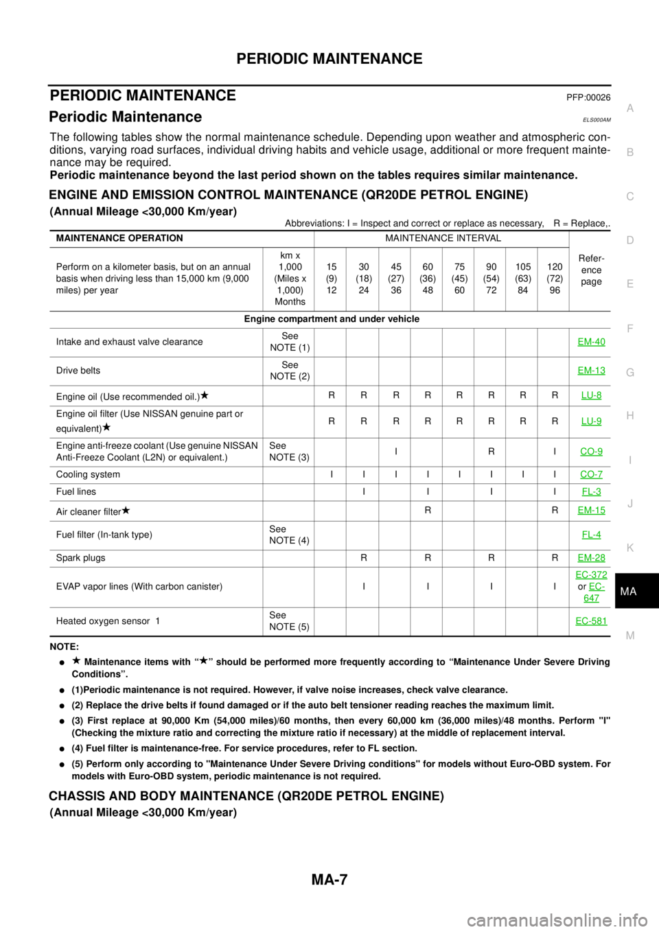
The following tables show the normal maintenance schedule. Depending upon weather and atmospheric con-
ditions, varying road surfaces, individual driving habits and vehicle usage, additional or more frequent mainte-
nance may be required.
Periodic maintenance beyond the last period shown on the tables requires similar maintenance.
ENGINE AND EMISSION CONTROL MAINTENANCE (QR20DE PETROL ENGINE)
(Annual Mileage <30,000 Km/year)
Abbreviations: I = Inspect and correct or replace as necessary, R = Replace,.
NOTE:
lMaintenance items with “ ” should be performed more frequently according to “Maintenance Under Severe Driving
Conditions”.
l(1)Periodic maintenance is not required. However, if valve noise increases, check valve clearance.
l(2) Replace the drive belts if found damaged or if the auto belt tensioner reading reaches the maximum limit.
l(3) First replace at 90,000 Km (54,000 miles)/60 months, then every 60,000 km (36,000 miles)/48 months. Perform "I"
(Checking the mixture ratio and correcting the mixture ratio if necessary) at the middle of replacement interval.
l(4) Fuel filter is maintenance-free. For service procedures, refer to FL section.
l(5) Perform only according to "Maintenance Under Severe Driving conditions" for models without Euro-OBD system. For
models with Euro-OBD system, periodic maintenance is not required.
CHASSIS AND BODY MAINTENANCE (QR20DE PETROL ENGINE)
(Annual Mileage <30,000 Km/year)
MAINTENANCE OPERATIONMAINTENANCE INTERVAL
Refer-
ence
page Perform on a kilometer basis, but on an annual
basis when driving less than 15,000 km (9,000
miles) per yearkm x
1,000
(Miles x
1,000)
Months15
(9)
1230
(18)
2445
(27)
3660
(36)
4875
(45)
6090
(54)
72105
(63)
84120
(72)
96
Engine compartment and under vehicle
Intake and exhaust valve clearanceSee
NOTE (1)EM-40
Drive beltsSee
NOTE (2)EM-13
Engine oil (Use recommended oil.)R R RRRRRRLU-8
Engine oil filter (Use NISSAN genuine part or
equivalent)R R RRRRRRLU-9
Engine anti-freeze coolant (Use genuine NISSAN
Anti-Freeze Coolant (L2N) or equivalent.)See
NOTE (3)IRICO-9
Coolingsystem I I IIIIIICO-7
Fuel lines I I I IFL-3
Air cleaner filterRREM-15
Fuel filter (In-tank type)See
NOTE (4)FL-4
Spark plugs R R R REM-28
EVAP vapor lines (With carbon canister) I I I IEC-372orEC-
647
Heated oxygen sensor 1See
NOTE (5)EC-581
Page 2500 of 3066
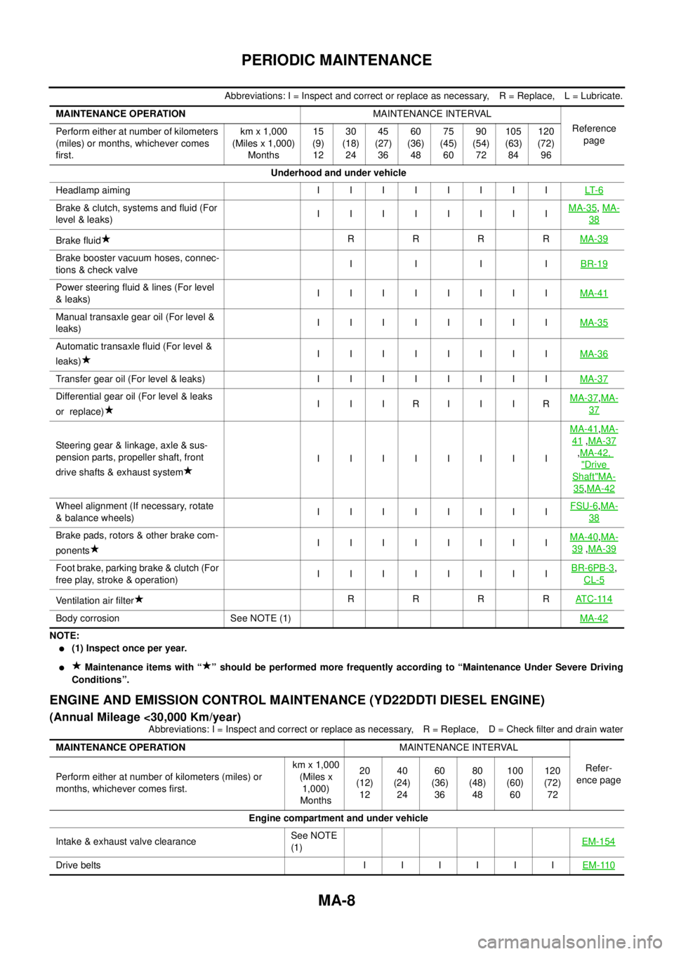
MA-8
PERIODIC MAINTENANCE
Abbreviations: I = Inspect and correct or replace as necessary, R = Replace, L = Lubricate.
NOTE:
l(1) Inspect once per year.
lMaintenance items with “ ” should be performed more frequently according to “Maintenance Under Severe Driving
Conditions”.
ENGINE AND EMISSION CONTROL MAINTENANCE (YD22DDTI DIESEL ENGINE)
(Annual Mileage <30,000 Km/year)
Abbreviations: I = Inspect and correct or replace as necessary, R = Replace, D = Check filter and drain water MAINTENANCE OPERATIONMAINTENANCE INTERVAL
Reference
page Perform either at number of kilometers
(miles) or months, whichever comes
first.km x 1,000
(Miles x 1,000)
Months15
(9)
1230
(18)
2445
(27)
3660
(36)
4875
(45)
6090
(54)
72105
(63)
84120
(72)
96
Underhood and under vehicle
Headlampaiming IIIIIIIILT- 6
Brake & clutch, systems and fluid (For
level & leaks)IIIIIIIIMA-35,MA-
38
Brake fluidRRRRMA-39
Brake booster vacuum hoses, connec-
tions & check valveIIIIBR-19
Power steering fluid & lines (For level
&leaks)IIIIIIIIMA-41
Manual transaxle gear oil (For level &
leaks)IIIIIIIIMA-35
Automatic transaxle fluid (For level &
leaks)IIIIIIIIMA-36
Transfer gear oil (For level & leaks) I I I I I I I IMA-37
Differential gear oil (For level & leaks
or replace)I I IRI I IRMA-37,MA-
37
Steering gear & linkage, axle & sus-
pension parts, propeller shaft, front
drive shafts & exhaust systemIIIIIIIIMA-41
,MA-
41,MA-37
,MA-42,
"Drive
Shaft"MA-
35,MA-42
Wheel alignment (If necessary, rotate
& balance wheels)IIIIIIIIFSU-6,MA-
38
Brake pads, rotors & other brake com-
ponentsIIIIIIIIMA-40,MA-
39,MA-39
Foot brake, parking brake & clutch (For
free play, stroke & operation)IIIIIIIIBR-6PB-3,
CL-5
Ventilation air filterRRRRAT C - 11 4
Body corrosion See NOTE (1)MA-42
MAINTENANCE OPERATIONMAINTENANCE INTERVAL
Refer-
ence page Perform either at number of kilometers (miles) or
months, whichever comes first.km x 1,000
(Miles x
1,000)
Months20
(12)
1240
(24)
2460
(36)
3680
(48)
48100
(60)
60120
(72)
72
Engine compartment and under vehicle
Intake & exhaust valve clearanceSee NOTE
(1)EM-154
Drivebelts IIIIIIEM-110