tow NISSAN X-TRAIL 2003 Electronic Repair Manual
[x] Cancel search | Manufacturer: NISSAN, Model Year: 2003, Model line: X-TRAIL, Model: NISSAN X-TRAIL 2003Pages: 3066, PDF Size: 51.47 MB
Page 13 of 3066
PRECAUTIONS
AT-7
D
E
F
G
H
I
J
K
L
MA
B
AT
lAfter performing each TROUBLE DIAGNOSIS, perform
“DTC (Diagnostic Trouble Code) CONFIRMATION PROCE-
DURE”.
The DTC should not be displayed in the “DTC CONFIRMA-
TION PROCEDURE” if the repair is completed.
lBefore proceeding with disassembly, thoroughly clean the out-
side of the transaxle. It is important to prevent the internal parts
from becoming contaminated by dirt or other foreign matter.
lDisassembly should be done in a clean work area.
lUse lint-free cloth or towels for wiping parts clean. Common
shop rags can leave fibers that could interfere with the operation
of the transaxle.
lPlace disassembled parts in order for easier and proper assembly.
lAll parts should be carefully cleaned with a general purpose, non-flammable solvent before inspection or
reassembly.
lGaskets, seals and O-rings should be replaced any time the transaxle is disassembled.
lIt is very important to perform functional tests whenever they are indicated.
lThe valve body contains precision parts and requires extreme care when parts are removed and serviced.
Place disassembled valve body parts in order for easier and proper assembly. Care will also prevent
springs and small parts from becoming scattered or lost.
lProperly installed valves, sleeves, plugs, etc. will slide along bores in valve body under their own weight.
lBefore assembly, apply a coat of recommended ATF to all parts. Apply petroleum jelly to protect O-rings
and seals, or hold bearings and washers in place during assembly. Do not use grease.
lExtreme care should be taken to avoid damage to O-rings, seals and gaskets when assembling.
lAfter overhaul, refill the transaxle with new ATF.
lWhen the A/T drain plug is removed, only some of the fluid is drained. Old A/T fluid will remain in torque
converter and ATF cooling system.
Always follow the procedures under “Changing A/T Fluid” in the AT section when changing A/T fluid. Refer
to “Changing A/T Fluid”,AT-13, "
A/T FLUID".
Service Notice or PrecautionsECS004Q3
FAI L-S AFE
The TCM has an electronic Fail-Safe (limp home mode). This allows the vehicle to be driven even if a major
electrical input/output device circuit is damaged.
Under Fail-Safe, the vehicle always runs in third gear, even with a shift lever position of “1”, “2” or “D”. The cus-
tomer may complain of sluggish or poor acceleration.
When the ignition key is turned “ON” following Fail-Safe operation, O/D OFF indicator lamp blinks for about 8
seconds. Refer to SELF-DIAGNOSTIC PROCEDURE(WITHOUT CONSULT-II)",AT- 2 7 3 , "
Diagnostic Proce-
dure Without CONSULT-II"(EXCEPT FOR EURO-OBD) or "TCM Self-diagnostic Procedure(NO TOOLS)",
AT- 5 1 , "
TCM SELF-DIAGNOSTIC PROCEDURE (NO TOOLS)"(EURO-OBD).
The blinking of the O/D OFF indicator lamp for about 8 seconds will appear only once and be cleared. The
customer may resume normal driving conditions.
Always follow the “WORK FLOW”, refer toAT-284, "
Work Flow"(EXCEPT FOR Euro-OBD) orAT-61, "Work
Flow"(Euro-OBD).
The SELF-DIAGNOSIS results will be as follows:
lThe first SELF-DIAGNOSIS will indicate damage to the vehicle speed sensor or the revolution sensor.
lDuring the next SELF-DIAGNOSIS, performed after checking the sensor, no damages will be indicated.
TORQUE CONVERTER SERVICE
The torque converter should be replaced under any of the following conditions:
lExternal leaks in the hub weld area.
lConverter hub is scored or damaged.
lConverter pilot is broken, damaged or fits poorly into crankshaft.
lSteel particles are found after flushing the cooler and cooler lines.
lPump is damaged or steel particles are found in the converter.
SAT652J
Page 687 of 3066
BLOWER UNIT
ATC-109
C
D
E
F
G
H
I
K
L
MA
B
AT C
BLOWER UNITPFP:27200
Removal and InstallationEJS000UL
REMOVAL
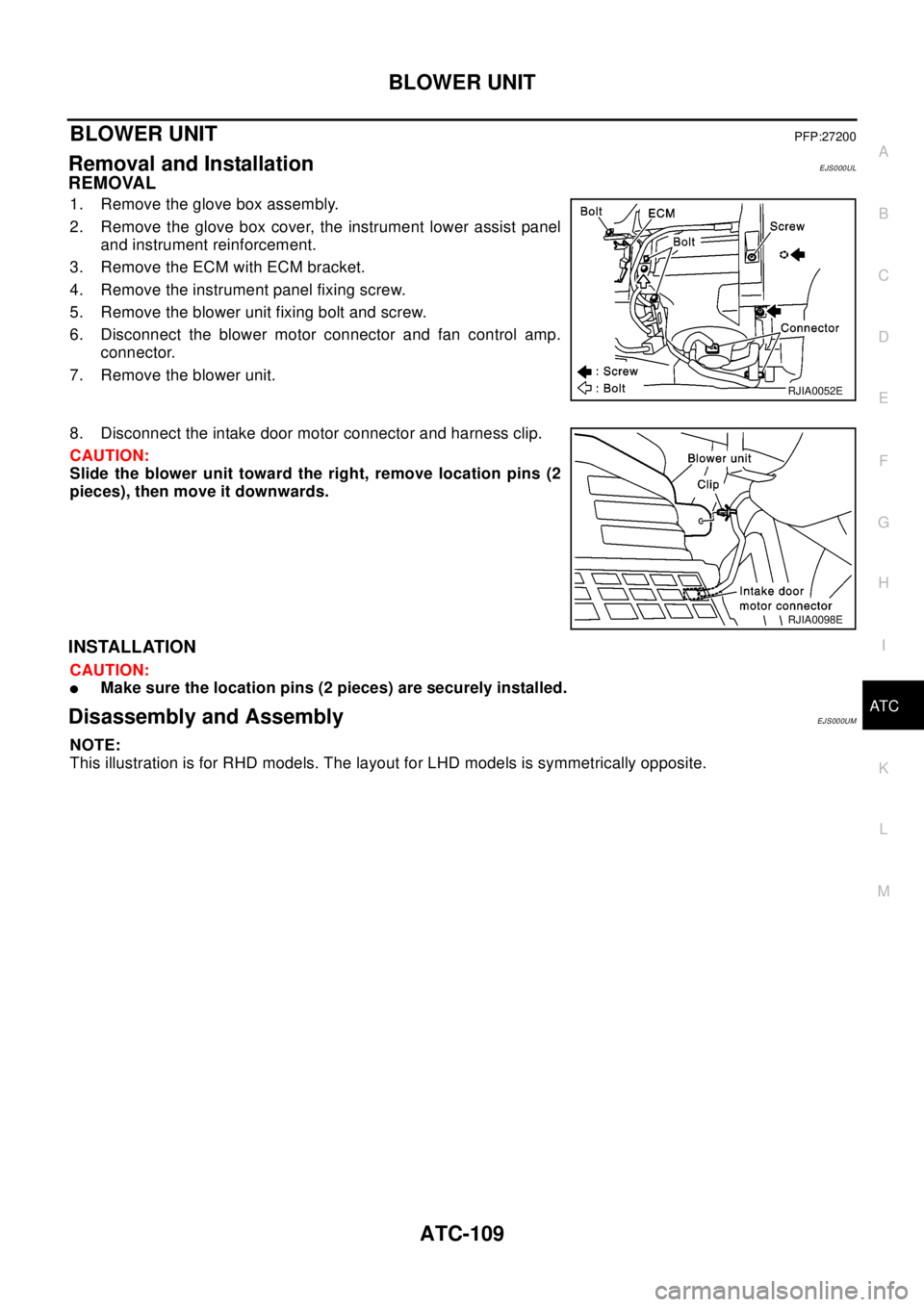
1. Remove the glove box assembly.
2. Remove the glove box cover, the instrument lower assist panel
and instrument reinforcement.
3. Remove the ECM with ECM bracket.
4. Remove the instrument panel fixing screw.
5. Remove the blower unit fixing bolt and screw.
6. Disconnect the blower motor connector and fan control amp.
connector.
7. Remove the blower unit.
8. Disconnect the intake door motor connector and harness clip.
CAUTION:
Slide the blower unit toward the right, remove location pins (2
pieces), then move it downwards.
INSTALLATION
CAUTION:
lMake sure the location pins (2 pieces) are securely installed.
Disassembly and AssemblyEJS000UM
NOTE:
This illustration is for RHD models. The layout for LHD models is symmetrically opposite.
RJIA0052E
RJIA0098E
Page 750 of 3066
BL-6
HOOD
Install in the reverse order of removal.
Removal and Installation of Hood Lock ControlEIS000KH
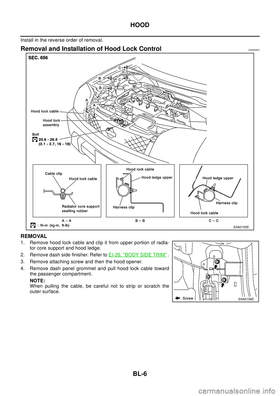
REMOVAL
1. Remove hood lock cable and clip it from upper portion of radia-
tor core support and hood ledge.
2. Remove dash side finisher. Refer toEI-26, "
BODY SIDE TRIM".
3. Remove attaching screw and then the hood opener.
4. Remove dash panel grommet and pull hood lock cable toward
the passenger compartment.
NOTE:
When pulling the cable, be careful not to strip or scratch the
outer surface.
SIIA0155E
SIIA0156E
Page 800 of 3066
BL-56
FRONT DOOR LOCK
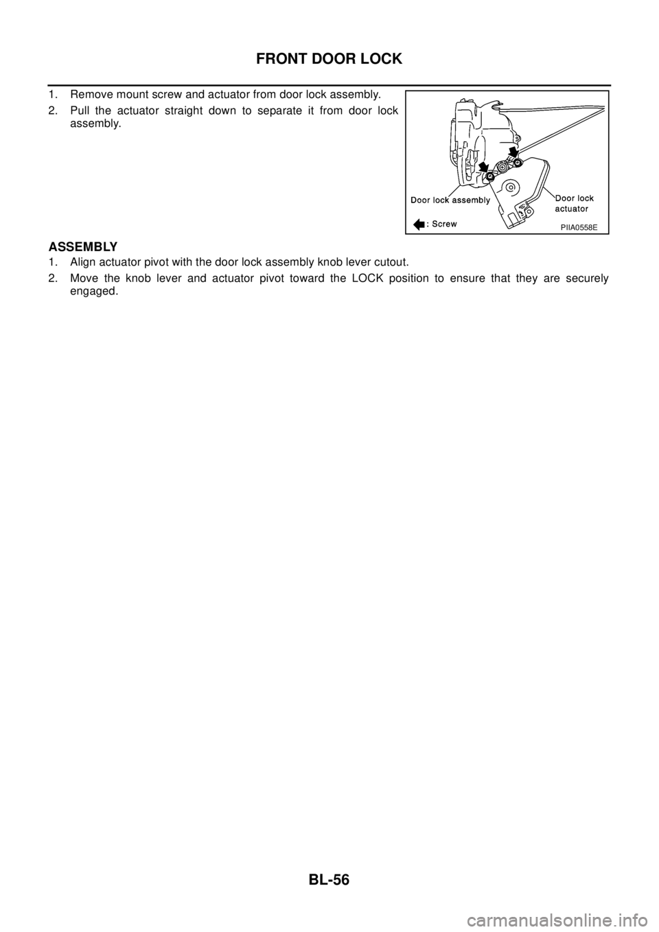
1. Remove mount screw and actuator from door lock assembly.
2. Pull the actuator straight down to separate it from door lock
assembly.
ASSEMBLY
1. Align actuator pivot with the door lock assembly knob lever cutout.
2. Move the knob lever and actuator pivot toward the LOCK position to ensure that they are securely
engaged.
PIIA0558E
Page 803 of 3066
REAR DOOR LOCK
BL-59
C
D
E
F
G
H
J
K
L
MA
B
BL
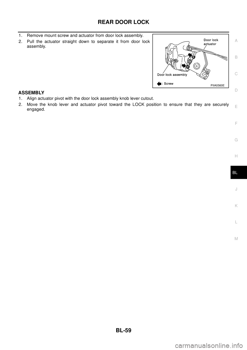
1. Remove mount screw and actuator from door lock assembly.
2. Pull the actuator straight down to separate it from door lock
assembly.
ASSEMBLY
1. Align actuator pivot with the door lock assembly knob lever cutout.
2. Move the knob lever and actuator pivot toward the LOCK position to ensure that they are securely
engaged.
PIIA0560E
Page 841 of 3066
BRAKE PEDAL
BR-7
C
D
E
G
H
I
J
K
L
MA
B
BR
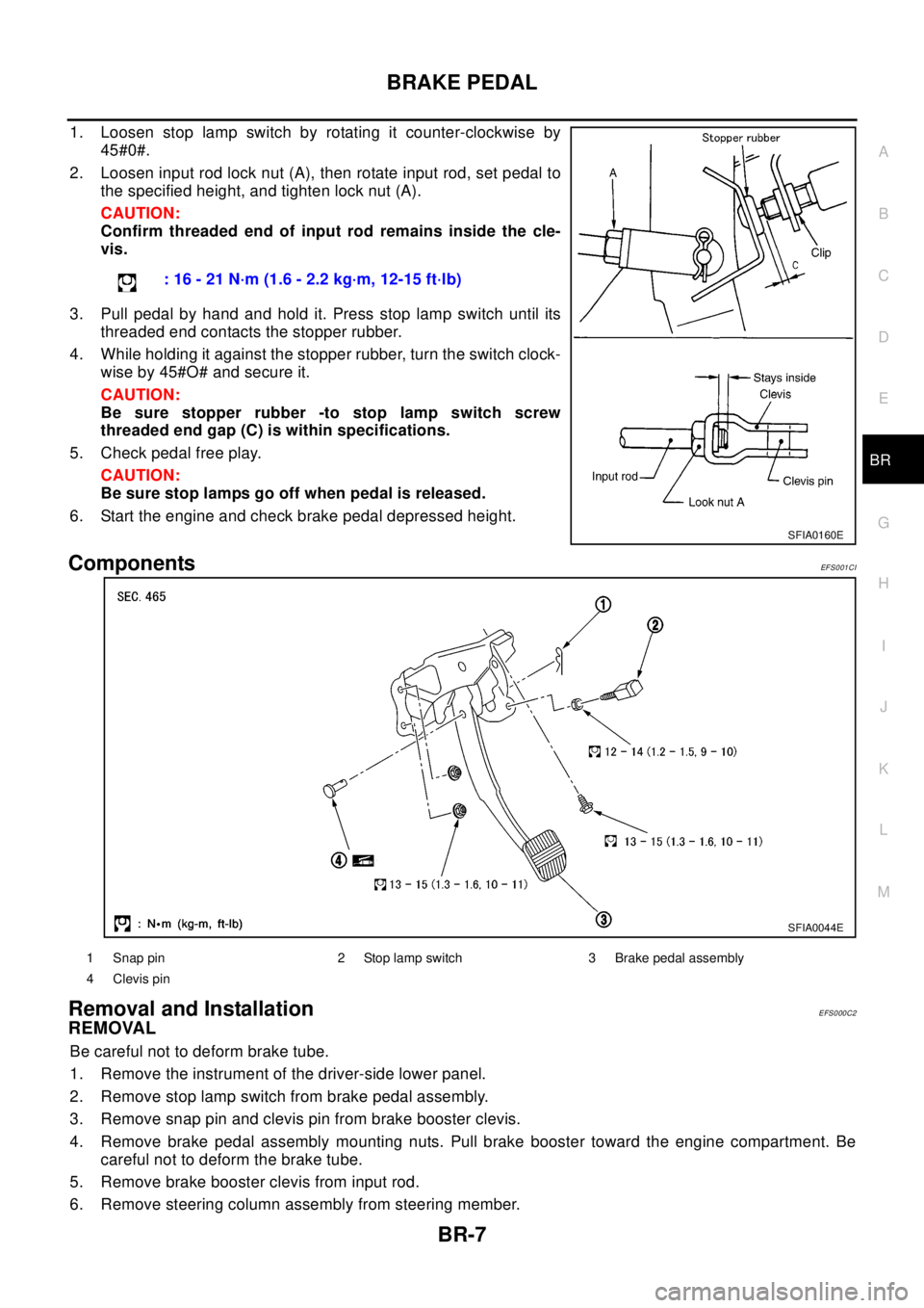
1. Loosen stop lamp switch by rotating it counter-clockwise by
45#0#.
2. Loosen input rod lock nut (A), then rotate input rod, set pedal to
the specified height, and tighten lock nut (A).
CAUTION:
Confirm threaded end of input rod remains inside the cle-
vis.
3. Pull pedal by hand and hold it. Press stop lamp switch until its
threaded end contacts the stopper rubber.
4. While holding it against the stopper rubber, turn the switch clock-
wise by 45#O# and secure it.
CAUTION:
Be sure stopper rubber -to stop lamp switch screw
threaded end gap (C) is within specifications.
5. Check pedal free play.
CAUTION:
Be sure stop lamps go off when pedal is released.
6. Start the engine and check brake pedal depressed height.
ComponentsEF S0 01 CI
Removal and InstallationEFS000C2
REMOVAL
Be careful not to deform brake tube.
1. Remove the instrument of the driver-side lower panel.
2. Remove stop lamp switch from brake pedal assembly.
3. Remove snap pin and clevis pin from brake booster clevis.
4. Remove brake pedal assembly mounting nuts. Pull brake booster toward the engine compartment. Be
careful not to deform the brake tube.
5. Remove brake booster clevis from input rod.
6. Remove steering column assembly from steering member.: 16 - 21 N·m (1.6 - 2.2 kg·m, 12-15 ft·lb)
SFIA0160E
SFIA0044E
1 Snap pin 2 Stop lamp switch 3 Brake pedal assembly
4 Clevis pin
Page 842 of 3066
BR-8
BRAKE PEDAL
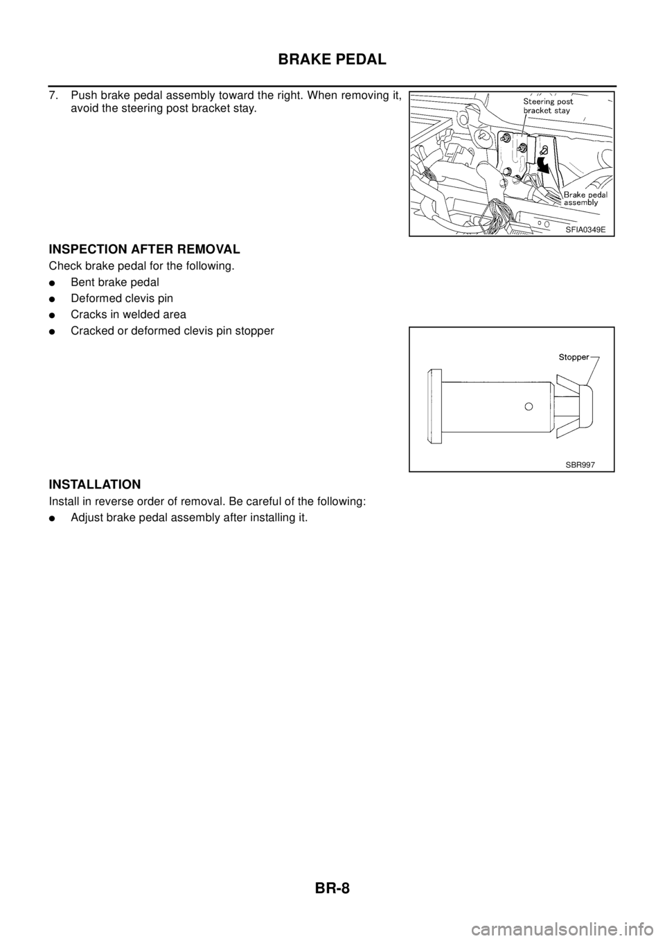
7. Push brake pedal assembly toward the right. When removing it,
avoid the steering post bracket stay.
INSPECTION AFTER REMOVAL
Check brake pedal for the following.
lBent brake pedal
lDeformed clevis pin
lCracks in welded area
lCracked or deformed clevis pin stopper
INSTALLATION
Install in reverse order of removal. Be careful of the following:
lAdjust brake pedal assembly after installing it.
SFIA0349E
SBR997
Page 1072 of 3066
DI-18
COMBINATION METERS (LHD MODELS)
The Fuel Gauge Does Not Move to F-position.
EKS002ZK
1.QUESTIONNAIRE 1
Does it take a long time for the pointer to move to F-position?
YES?
YES >> GO TO 2.
NO >> GO TO 3.
2.QUESTIONNAIRE 2
Was the vehicle fueled with the ignition switch ON?
YES?
YES >> Be sure to fuel the vehicle with the ignition switch OFF. Otherwise it will take a long time to move
to F-position because of the characteristic of the fuel gauge.
NO >> GO TO 3.
3.QUESTIONNAIRE 3
Is the floor or the vehicle inclined?
YES?
YES >> It may not be filled fully.
NO >> GO TO 4.
4.QUESTIONNAIRE 4
During driving, does the fuel gauge pointer move gradually toward E-position?
YES?
YES >> Check the components. Refer toDI-19, "Electrical Components Inspection".
NO >> The float arm may interfere or bind with any of the components in the fuel tank.
The Fuel Gauge Does Not Work.EKS002ZL
1.HARNESS CONNECTOR INSPECTION
1. Turn the ignition switch OFF.
2. Check combination meter, fuel level sensor unit, sub fuel level sensor unit and terminals (meter-side,
module-side, and harness-side) for poor connection and bend.
OK or NG
OK >> GO TO 2.
NG >> Repair connector.
2.CHECK INSTALLATION CONDITION
Check fuel level sensor unit or sub fuel level sensor unit installation (refer toFL-4, "
FUEL LEVEL SENSOR
UNIT, FUEL FILTER AND FUEL PUMP ASSEMBLY"for QR engine models orFL-17, "FUEL LEVEL SEN-
SOR UNIT"for YD engine models, and check whether the float arm interferes or binds with any components
inside the arm.
OK or NG
OK >> Fuel level sensor unit is OK.
NG >> Check fuel level sensor unit or sub fuel level sensor unit. Refer toDI-19, "
Electrical Components
Inspection".
Page 1090 of 3066
DI-36
COMBINATION METERS (RHD MODELS)
The Fuel Gauge Does Not Move to F-position.
EKS0030V
1.QUESTIONNAIRE 1
Does it take a long time for the pointer to move to F-position?
YES?
YES >> GO TO 2.
NO >> GO TO 3.
2.QUESTIONNAIRE 2
Was the vehicle fueled with the ignition switch ON?
YES ?
YES >> Be sure to fuel the vehicle with the ignition switch OFF. Otherwise it will take a long time to move
to F-position because of the characteristic of the fuel gauge.
NO >> GO TO 3.
3.QUESTIONNAIRE 3
Is the floor or the vehicle inclined?
YES?
YES >> It may not be filled fully.
NO >> GO TO 4.
4.QUESTIONNAIRE 4
During driving, does the fuel gauge pointer move gradually toward E-position?
YES ?
YES >> Check the components. Refer toDI-37, "Electrical Components Inspection".
NO >> The float arm may interfere or bind with any of the components in the fuel tank.
The Fuel Gauge Does Not Work.EKS0030W
1.HARNESS CONNECTOR INSPECTION
1. Turn the ignition switch OFF.
2. Check combination meter, fuel level sensor unit, sub fuel level sensor unit and terminals (meter-side,
module-side, and harness-side) for poor connection and bend.
OK or NG
OK >> GO TO 2.
NG >> Repair connector.
2.CHECK INSTALLATION CONDITION
Check fuel level sensor unit or sub fuel level sensor unit installation (refer toFL-4, "
FUEL LEVEL SENSOR
UNIT, FUEL FILTER AND FUEL PUMP ASSEMBLY"for QR engine models orFL-17, "FUEL LEVEL SEN-
SOR UNIT"for YD engine models, and check whether the float arm interferes or binds with any components
inside the arm.
OK or NG
OK >> Fuel level sensor unit is OK.
NG >> Check fuel level sensor unit or sub fuel level sensor unit. Refer toDI-37, "
Electrical Components
Inspection".
Page 1204 of 3066
![NISSAN X-TRAIL 2003 Electronic Repair Manual EC-90
[QR (WITH EURO-OBD)]
TROUBLE DIAGNOSIS
DATA MONITOR MODE
Monitored Item
´: Applicable
Monitored item
[Unit]ECM
INPUT
SIG-
NALSMAIN
SIG-
NALSCAN
DIAG
SUP-
PORT
MNTRDescription Remarks
ENG SPEED NISSAN X-TRAIL 2003 Electronic Repair Manual EC-90
[QR (WITH EURO-OBD)]
TROUBLE DIAGNOSIS
DATA MONITOR MODE
Monitored Item
´: Applicable
Monitored item
[Unit]ECM
INPUT
SIG-
NALSMAIN
SIG-
NALSCAN
DIAG
SUP-
PORT
MNTRDescription Remarks
ENG SPEED](/img/5/57402/w960_57402-1203.png)
EC-90
[QR (WITH EURO-OBD)]
TROUBLE DIAGNOSIS
DATA MONITOR MODE
Monitored Item
´: Applicable
Monitored item
[Unit]ECM
INPUT
SIG-
NALSMAIN
SIG-
NALSCAN
DIAG
SUP-
PORT
MNTRDescription Remarks
ENG SPEED [rpm]´´
lIndicates the engine speed computed
from the signal of the crankshaft position
sensor (POS).
lAccuracy becomes poor if engine
speed drops below the idle rpm.
lIf the signal is interrupted while the
engine is running, an abnormal
value may be indicated.
MAS A/F SE-B1 [V]´´
lThe signal voltage of the mass air flow
sensor is displayed.lWhen the engine is stopped, a
certain value is indicated.
COOLAN TEMP/S
[°C] or [°F]´´
lThe engine coolant temperature (deter-
mined by the signal voltage of the
engine coolant temperature sensor) is
displayed.
lWhen the engine coolant tempera-
ture sensor is open or short-cir-
cuited, ECM enters fail-safe mode.
The engine coolant temperature
determined by the ECM is dis-
played.
HO2S1 (B1) [V]´´
lThe signal voltage of the heated oxygen
sensor 1 is displayed.
HO2S2 (B1) [V]´´
lThe signal voltage of the heated oxygen
sensor 2 is displayed.
HO2S1 MNTR (B1)
[RICH/LEAN]´´
lDisplay of heated oxygen sensor 1 sig-
nal during air-fuel ratio feedback control:
RICH ... means the mixture became
“rich”, and control is being affected
toward a leaner mixture.
LEAN ... means the mixture became
“lean”, and control is being affected
toward a rich mixture.lAfter turning ON the ignition
switch, “RICH” is displayed until
air-fuel mixture ratio feedback
control begins.
lWhen the air-fuel ratio feedback is
clamped, the value just before the
clamping is displayed continu-
ously.
HO2S2 MNTR (B1)
[RICH/LEAN]´
lDisplay of heated oxygen sensor 2 sig-
nal:
RICH ... means the amount of oxygen
after three way catalyst is relatively
small.
LEAN ... means the amount of oxygen
after three way catalyst is relatively
large.
lWhen the engine is stopped, a
certain value is indicated.
VHCL SPEED SE
[km/h] or [mph]´´
lThe vehicle speed computed from the
vehicle speed signal is displayed.
BATTERY VOLT
[V]´´
lThe power supply voltage of ECM is dis-
played.
ACCEL SEN 1 [V]´´
lThe accelerator pedal position sensor
signal voltage is displayed.
ACCEL SEN 2 [V]´
THRTL SEN 1 [V]´´
lThe throttle position sensor signal volt-
age is displayed.
THRTL SEN 2 [V]´
INT/ATEMPSE
[°C] or [°F]´´
lThe intake air temperature (determined
by the signal voltage of the intake air
temperature sensor) is indicated.
START SIGNAL
[ON/OFF]´´
lIndicates [ON/OFF] condition from the
starter signal.lAfter starting the engine, [OFF] is
displayed regardless of the starter
signal.