NISSAN X-TRAIL 2005 Service Repair Manual
X-TRAIL 2005
NISSAN
NISSAN
https://www.carmanualsonline.info/img/5/57403/w960_57403-0.png
NISSAN X-TRAIL 2005 Service Repair Manual
Trending: EC-275, Component Inspection, power steering fluid, engine overheat, air bleeding, BRC-26, Idle air volume, headlights
Page 4131 of 4555
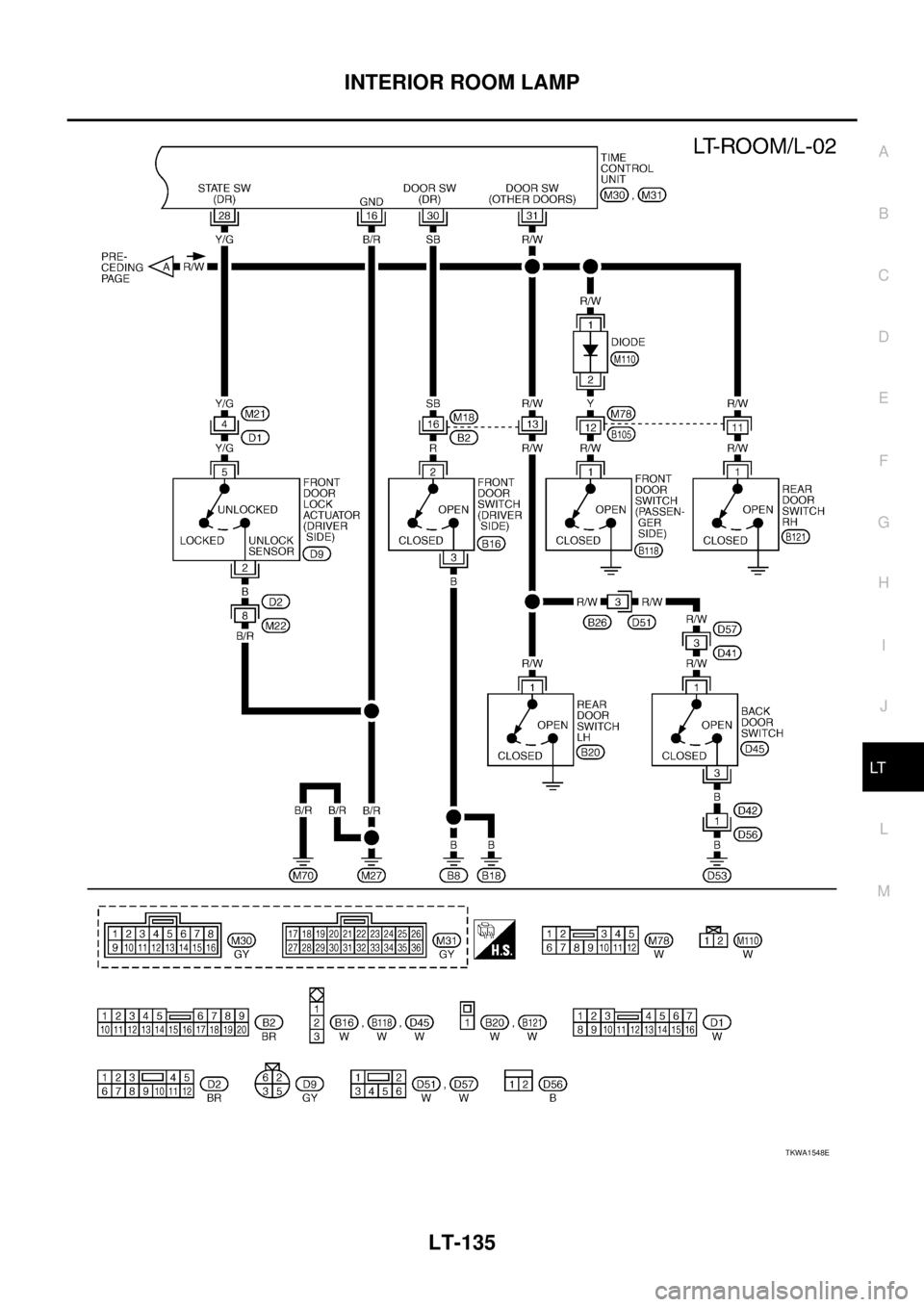
INTERIOR ROOM LAMP
LT-135
C
D
E
F
G
H
I
J
L
MA
B
LT
TKWA1548E
Page 4132 of 4555
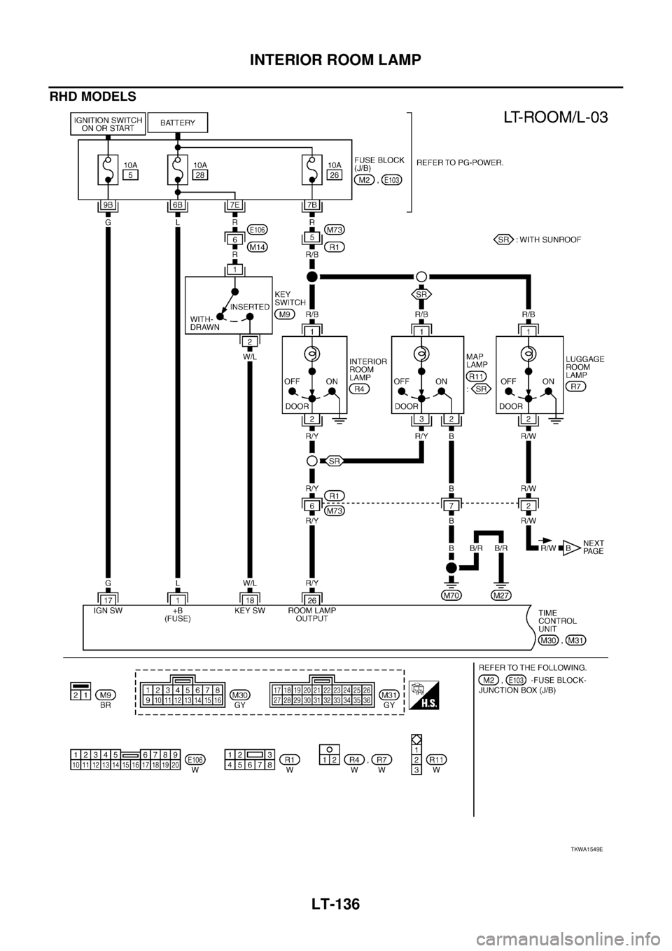
LT-136
INTERIOR ROOM LAMP
RHD MODELS
TKWA1549E
Page 4133 of 4555
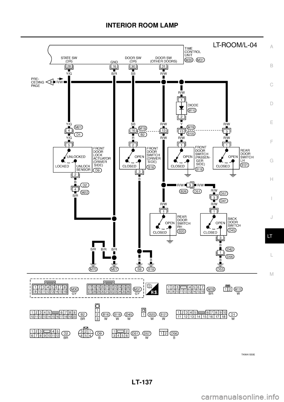
INTERIOR ROOM LAMP
LT-137
C
D
E
F
G
H
I
J
L
MA
B
LT
TKWA1550E
Page 4134 of 4555
LT-138
INTERIOR ROOM LAMP
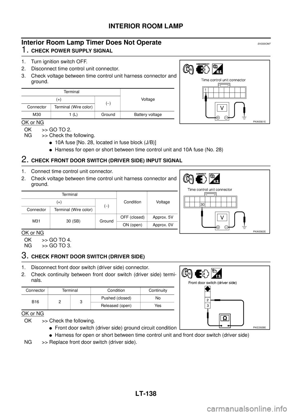
Interior Room Lamp Timer Does Not OperateEKS00OM7
1. CHECK POWER SUPPLY SIGNAL
1. Turn ignition switch OFF.
2. Disconnect time control unit connector.
3. Check voltage between time control unit harness connector and
ground.
OK or NG
OK >> GO TO 2.
NG >> Check the following.
�10A fuse [No. 28, located in fuse block (J/B)]
�Harness for open or short between time control unit and 10A fuse (No. 28)
2. CHECK FRONT DOOR SWITCH (DRIVER SIDE) INPUT SIGNAL
1. Connect time control unit connector.
2. Check voltage between time control unit harness connector and
ground.
OK or NG
OK >> GO TO 4.
NG >> GO TO 3.
3. CHECK FRONT DOOR SWITCH (DRIVER SIDE)
1. Disconnect front door switch (driver side) connector.
2. Check continuity between front door switch (driver side) termi-
nals.
OK or NG
OK >> Check the following.
�Front door switch (driver side) ground circuit condition
�Harness for open or short between time control unit and front door switch (driver side)
NG >> Replace front door switch (driver side).
Te r m i n a l
Voltage (+)
(−)
Connector Terminal (Wire color)
M30 1 (L) Ground Battery voltage
PKIA5561E
Terminal
Condition Voltage (+)
(−)
Connector Terminal (Wire color)
M31 30 (SB) GroundOFF (closed) Approx. 5V
ON (open) Approx. 0V
PKIA5562E
Connector Terminal Condition Continuity
B16 2 3Pushed (closed) No
Released (open) Yes
PKIC0928E
Page 4135 of 4555
INTERIOR ROOM LAMP
LT-139
C
D
E
F
G
H
I
J
L
MA
B
LT
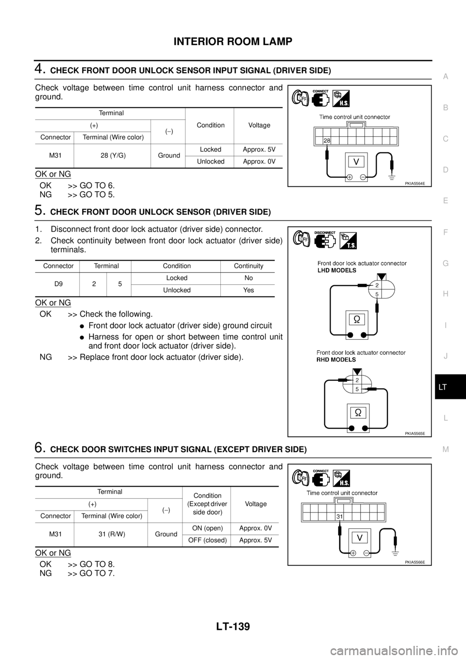
4. CHECK FRONT DOOR UNLOCK SENSOR INPUT SIGNAL (DRIVER SIDE)
Check voltage between time control unit harness connector and
ground.
OK or NG
OK >> GO TO 6.
NG >> GO TO 5.
5. CHECK FRONT DOOR UNLOCK SENSOR (DRIVER SIDE)
1. Disconnect front door lock actuator (driver side) connector.
2. Check continuity between front door lock actuator (driver side)
terminals.
OK or NG
OK >> Check the following.
�Front door lock actuator (driver side) ground circuit
�Harness for open or short between time control unit
and front door lock actuator (driver side).
NG >> Replace front door lock actuator (driver side).
6. CHECK DOOR SWITCHES INPUT SIGNAL (EXCEPT DRIVER SIDE)
Check voltage between time control unit harness connector and
ground.
OK or NG
OK >> GO TO 8.
NG >> GO TO 7.
Terminal
Condition Voltage (+)
(−)
Connector Terminal (Wire color)
M31 28 (Y/G) GroundLocked Approx. 5V
Unlocked Approx. 0V
PKIA5564E
Connector Terminal Condition Continuity
D9 2 5Locked No
Unlocked Yes
PKIA5565E
Terminal
Condition
(Except driver
side door)Vo l ta g e (+)
(−)
Connector Terminal (Wire color)
M31 31 (R/W) GroundON (open) Approx. 0V
OFF (closed) Approx. 5V
PKIA5566E
Page 4136 of 4555
LT-140
INTERIOR ROOM LAMP
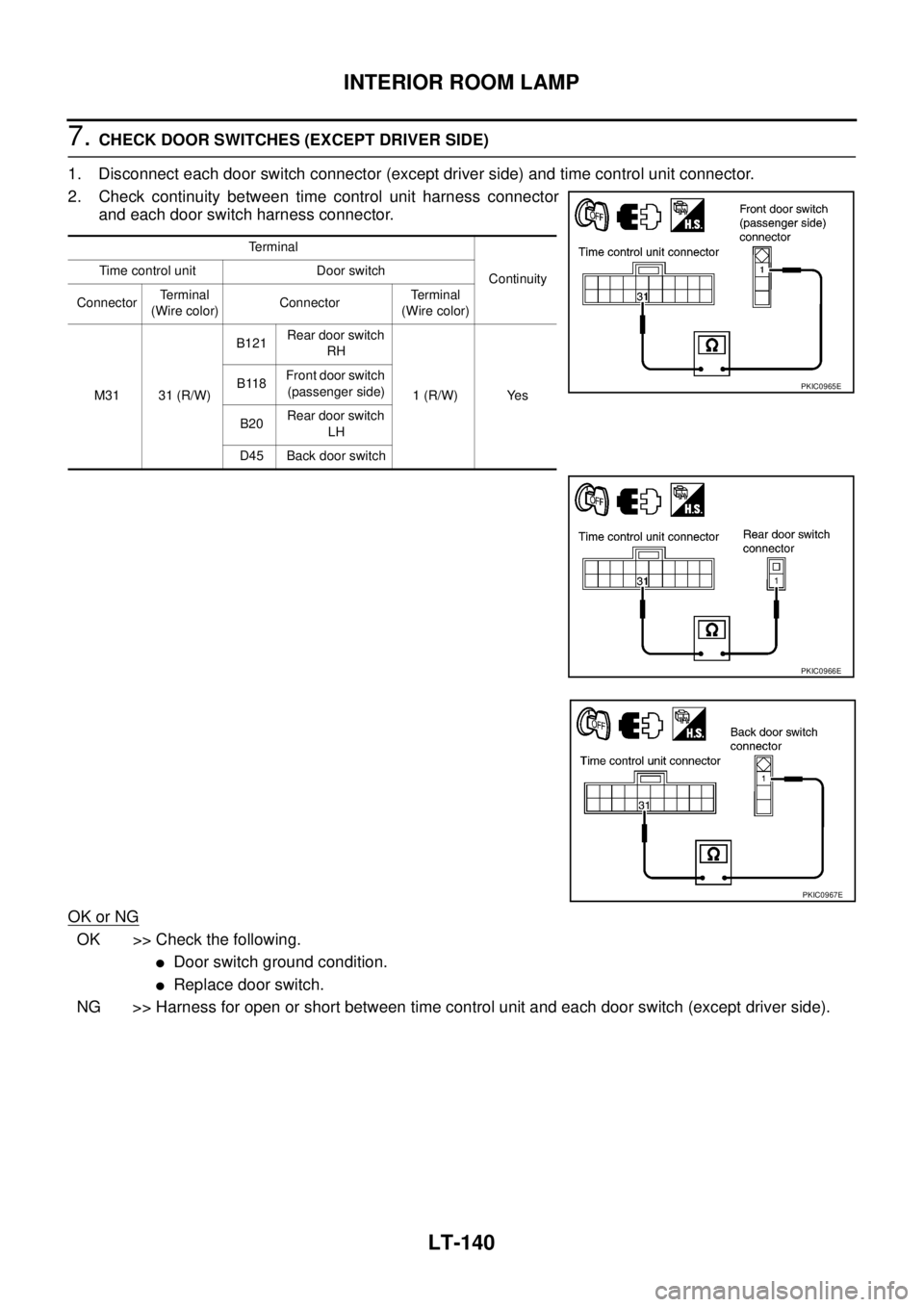
7. CHECK DOOR SWITCHES (EXCEPT DRIVER SIDE)
1. Disconnect each door switch connector (except driver side) and time control unit connector.
2. Check continuity between time control unit harness connector
and each door switch harness connector.
OK or NG
OK >> Check the following.
�Door switch ground condition.
�Replace door switch.
NG >> Harness for open or short between time control unit and each door switch (except driver side).
Terminal
Continuity Time control unit Door switch
ConnectorTerminal
(Wire color)ConnectorTerminal
(Wire color)
M31 31 (R/W)B121Rear door switch
RH
1 (R/W) Yes B118Front door switch
(passenger side)
B20Rear door switch
LH
D45 Back door switch
PKIC0965E
PKIC0966E
PKIC0967E
Page 4137 of 4555
INTERIOR ROOM LAMP
LT-141
C
D
E
F
G
H
I
J
L
MA
B
LT
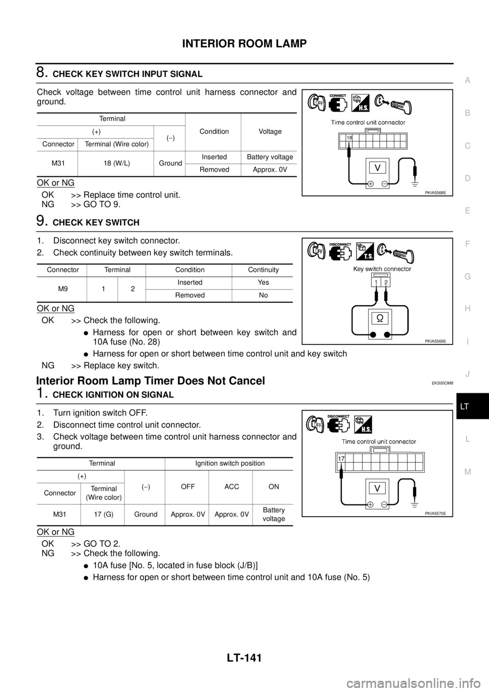
8. CHECK KEY SWITCH INPUT SIGNAL
Check voltage between time control unit harness connector and
ground.
OK or NG
OK >> Replace time control unit.
NG >> GO TO 9.
9. CHECK KEY SWITCH
1. Disconnect key switch connector.
2. Check continuity between key switch terminals.
OK or NG
OK >> Check the following.
�Harness for open or short between key switch and
10A fuse (No. 28)
�Harness for open or short between time control unit and key switch
NG >> Replace key switch.
Interior Room Lamp Timer Does Not CancelEKS00OM8
1. CHECK IGNITION ON SIGNAL
1. Turn ignition switch OFF.
2. Disconnect time control unit connector.
3. Check voltage between time control unit harness connector and
ground.
OK or NG
OK >> GO TO 2.
NG >> Check the following.
�10A fuse [No. 5, located in fuse block (J/B)]
�Harness for open or short between time control unit and 10A fuse (No. 5)
Terminal
Condition Voltage (+)
(−)
Connector Terminal (Wire color)
M31 18 (W/L) GroundInserted Battery voltage
Removed Approx. 0V
PKIA5568E
Connector Terminal Condition Continuity
M9 1 2Inserted Yes
Removed No
PKIA5569E
Terminal Ignition switch position
(+)
(−)OFFACCON
ConnectorTe r m i n a l
(Wire color)
M31 17 (G) Ground Approx. 0V Approx. 0VBattery
voltage
PKIA5570E
Page 4138 of 4555
LT-142
INTERIOR ROOM LAMP
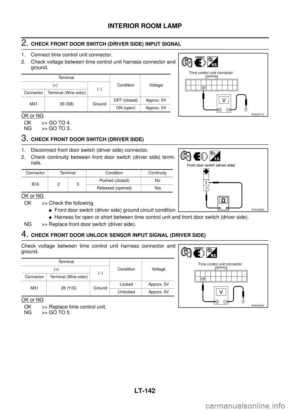
2. CHECK FRONT DOOR SWITCH (DRIVER SIDE) INPUT SIGNAL
1. Connect time control unit connector.
2. Check voltage between time control unit harness connector and
ground.
OK or NG
OK >> GO TO 4.
NG >> GO TO 3.
3. CHECK FRONT DOOR SWITCH (DRIVER SIDE)
1. Disconnect front door switch (driver side) connector.
2. Check continuity between front door switch (driver side) termi-
nals.
OK or NG
OK >> Check the following.
�Front door switch (driver side) ground circuit condition
�Harness for open or short between time control unit and front door switch (driver side).
NG >> Replace front door switch (driver side).
4. CHECK FRONT DOOR UNLOCK SENSOR INPUT SIGNAL (DRIVER SIDE)
Check voltage between time control unit harness connector and
ground.
OK or NG
OK >> Replace time control unit.
NG >> GO TO 5.
Terminal
Condition Voltage (+)
(−)
Connector Terminal (Wire color)
M31 30 (SB) GroundOFF (closed) Approx. 5V
ON (open) Approx. 0V
PKIA5571E
Connector Terminal Condition Continuity
B16 2 3Pushed (closed) No
Released (opened) Yes
PKIC0928E
Terminal
Condition Voltage (+)
(−)
Connector Terminal (Wire color)
M31 28 (Y/G) GroundLocked Approx. 5V
Unlocked Approx. 0V
PKIA5564E
Page 4139 of 4555
INTERIOR ROOM LAMP
LT-143
C
D
E
F
G
H
I
J
L
MA
B
LT
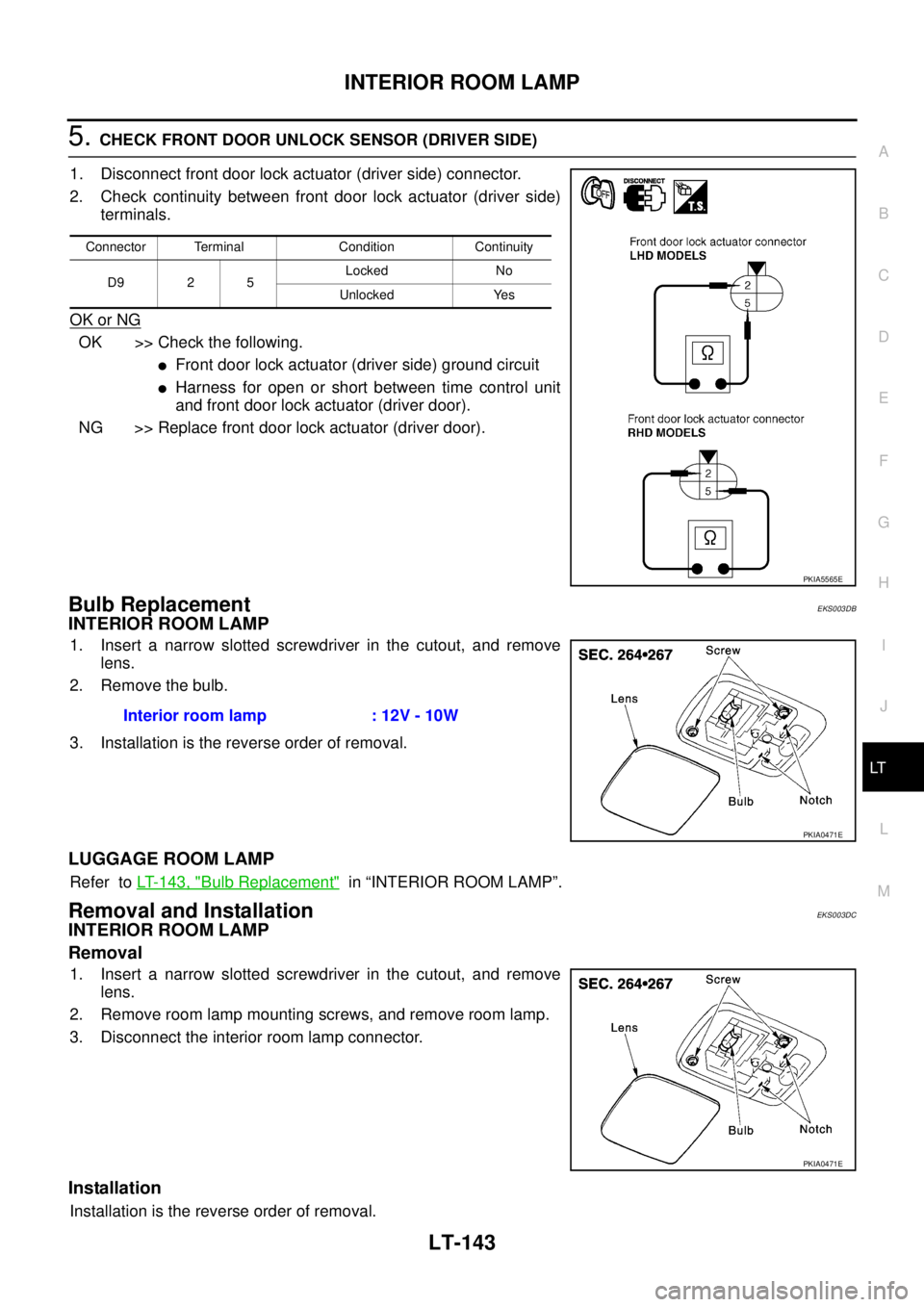
5. CHECK FRONT DOOR UNLOCK SENSOR (DRIVER SIDE)
1. Disconnect front door lock actuator (driver side) connector.
2. Check continuity between front door lock actuator (driver side)
terminals.
OK or NG
OK >> Check the following.
�Front door lock actuator (driver side) ground circuit
�Harness for open or short between time control unit
and front door lock actuator (driver door).
NG >> Replace front door lock actuator (driver door).
Bulb Replacement EKS003DB
INTERIOR ROOM LAMP
1. Insert a narrow slotted screwdriver in the cutout, and remove
lens.
2. Remove the bulb.
3. Installation is the reverse order of removal.
LUGGAGE ROOM LAMP
Refer to LT- 1 4 3 , "Bulb Replacement" in “INTERIOR ROOM LAMP”.
Removal and InstallationEKS003DC
INTERIOR ROOM LAMP
Removal
1. Insert a narrow slotted screwdriver in the cutout, and remove
lens.
2. Remove room lamp mounting screws, and remove room lamp.
3. Disconnect the interior room lamp connector.
Installation
Installation is the reverse order of removal.
Connector Terminal Condition Continuity
D9 2 5Locked No
Unlocked Yes
PKIA5565E
Interior room lamp : 12V - 10W
PKIA0471E
PKIA0471E
Page 4140 of 4555
LT-144
INTERIOR ROOM LAMP
LUGGAGE ROOM LAMP
Refer to LT- 1 4 3 , "Removal and Installation" in “INTERIOR ROOM LAMP”.
Trending: P1111, jacking points, height, door lock, gear shift, coolant level, air bleeding
