wheel OPEL ANTARA 2017.5 Manual user
[x] Cancel search | Manufacturer: OPEL, Model Year: 2017.5, Model line: ANTARA, Model: OPEL ANTARA 2017.5Pages: 225, PDF Size: 6.2 MB
Page 60 of 225

58StorageArmrest storage
Console box in front armrest
To open: pull up lever and lift the lid.
To close: lower lid and push it down
until it latches into position.
Centre console storage To access the storage compartment,
power outlet and AUX input, slide the
cupholder tray rearwards.
Power outlets 3 77.
AUX input - see Infotainment system
manual for further information.
Rear carrier system
The rear carrier system (Flex-Fix
system) allows bicycles to be
attached to a pull-out carrier
integrated into the vehicle floor. The
transportation of other objects is not
permitted.
The maximum load of the rear carrier
system is 40 kg. The maximum load
per bicycle is 20 kg.
The wheelbase of a bicycle must not
exceed 1.2 metres. Otherwise the
secure fastening of a bicycle is not possible.
If not in use, the carrier system must
be slid back into the vehicle floor.
A multifunction box is offered as an
accessory for the rear carrier system.
There must not be any objects on thebicycles that could become loose
during transportation.Caution
If the rear carrier system is
extended and the vehicle is fully
loaded, the chassis clearance will
be reduced.
Drive carefully whenever the road has a strong inclination or when
driving over a ramp, bump, etc.
Caution
Do not attach bicycles with carbon pedal cranks to bicycle carriers.
The bicycles might get damaged.
Extending
Open the tailgate.
Page 64 of 225

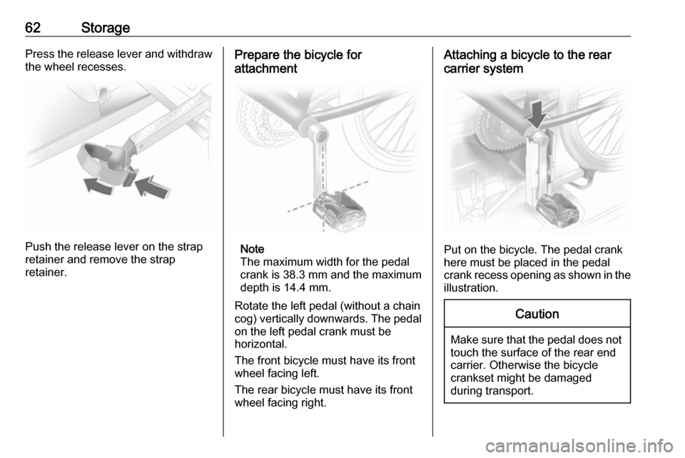
62StoragePress the release lever and withdraw
the wheel recesses.
Push the release lever on the strap
retainer and remove the strap
retainer.
Prepare the bicycle for
attachment
Note
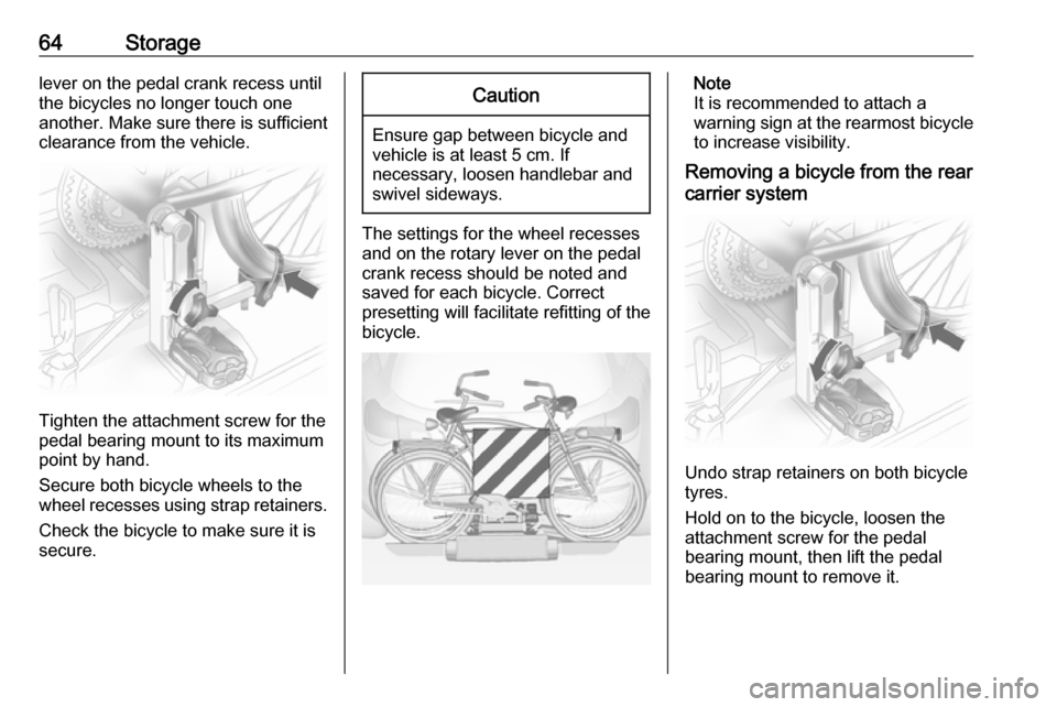
The maximum width for the pedal
crank is 38.3 mm and the maximum
depth is 14.4 mm.
Rotate the left pedal (without a chain
cog) vertically downwards. The pedal
on the left pedal crank must be
horizontal.
The front bicycle must have its front
wheel facing left.
The rear bicycle must have its front
wheel facing right.
Attaching a bicycle to the rear
carrier system
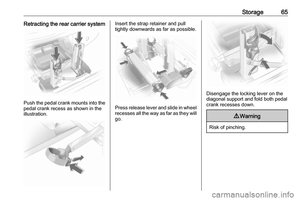
Put on the bicycle. The pedal crank
here must be placed in the pedal
crank recess opening as shown in the
illustration.
Caution
Make sure that the pedal does not
touch the surface of the rear end
carrier. Otherwise the bicycle
crankset might be damaged
during transport.
Page 65 of 225

Storage63
Insert pedal crank mount into outer
rail of each pedal crank recess from
above and slide downwards as far as
it will go.
Attach the pedal crank by rotating the
attachment screw on the pedal crank
mount.
Place the wheel recesses such that
the bicycle is more or less horizontal. Here, the distance between the
pedals and the tailgate should be at
least 5 cm.
Both bicycle tyres must be in the
wheel recesses.
Caution
Make sure to pull out the wheel
recesses as far as necessary to have both bicycle tyres placed in
the recesses. Otherwise a
horizontal mounting of the bicycle
is not ensured. Disregard could
lead to damage of the bicycle
wheels caused by hot exhaust
fumes.
Align the bicycle in the longitudinal direction of the vehicle: Slightly
loosen the pedal mount.
Place the bicycle upright using the
rotary lever on the pedal crank
recess.
If the two bicycles obstruct one
another, the relative positions of the
bicycles can be adapted by adjusting
the wheel recesses and the rotary
Page 66 of 225

64Storagelever on the pedal crank recess until
the bicycles no longer touch one
another. Make sure there is sufficient
clearance from the vehicle.
Tighten the attachment screw for the
pedal bearing mount to its maximum
point by hand.
Secure both bicycle wheels to the
wheel recesses using strap retainers.
Check the bicycle to make sure it is
secure.
Caution
Ensure gap between bicycle and
vehicle is at least 5 cm. If
necessary, loosen handlebar and swivel sideways.
The settings for the wheel recesses
and on the rotary lever on the pedal
crank recess should be noted and saved for each bicycle. Correct
presetting will facilitate refitting of the
bicycle.
Note
It is recommended to attach a
warning sign at the rearmost bicycle to increase visibility.
Removing a bicycle from the rear
carrier system
Undo strap retainers on both bicycle
tyres.
Hold on to the bicycle, loosen the attachment screw for the pedal
bearing mount, then lift the pedal
bearing mount to remove it.
Page 67 of 225

Storage65Retracting the rear carrier system
Push the pedal crank mounts into the
pedal crank recess as shown in the
illustration.
Insert the strap retainer and pull
tightly downwards as far as possible.
Press release lever and slide in wheel recesses all the way as far as they will
go.
Disengage the locking lever on the
diagonal support and fold both pedal
crank recesses down.
9 Warning
Risk of pinching.
Page 71 of 225

Storage69Caution
Do not allow objects to protrude
above the top of the rear floor
storage compartment, to avoid
damage to the storage area and
the load compartment floor.
Jack and vehicle tools 3 179.
Tyre repair kit 3 187.
Temporary spare wheel 3 193.
Lashing eyes
The lashing eyes are designed to
secure items against slippage, e.g.
using lashing straps or a luggage floor
net.
Two additional lashing eyes are
located in front of the rear seats.
Designed for carrying small, light
items only, a luggage floor net helps
keep loads from moving during sharp turns or quick starts and stops.
To install: attach the four net hooks to
the lashing eyes mounted on the load
compartment floor.
Warning triangle Stow the warning triangle below the
floor cover in the load compartment.
First aid kit Stow the first aid kit below the floorcover in the load compartment.
Fire extinguisher Stow the fire extinguisher securely in
the load compartment.Roof rack system
Roof rack
For safety reasons and to avoid
damage to the roof, the vehicle
approved roof rack system is
recommended. For further
information contact a workshop.
Fasten the roof rack to the roof rails
following the instructions that
accompany the system, ensuring that
the roof load is evenly distributed over the side or cross rails.
Loads must not be placed on the roof
surface. To prevent damage or loss,
check frequently that roof loads are
securely fastened.
Driving with a roof load affects the
vehicle centre of gravity; drive
carefully in crosswinds and do not
drive at high speeds.
Remove the roof rack when not in
use.
Page 73 of 225

Instruments and controls71Instruments and
controlsControls ....................................... 72
Steering wheel adjustment ........72
Steering wheel controls .............72
Horn ........................................... 72
Windscreen wiper/washer .........73
Rear window wiper/washer .......74
Outside temperature ..................75
Clock ......................................... 75
Power outlets ............................. 77
Warning lights, gauges and indi‐ cators ........................................... 78
Instrument cluster ......................78
Speedometer ............................. 78
Odometer .................................. 78
Trip odometer ............................ 79
Tachometer ............................... 79
Fuel gauge ................................ 79
Service display .......................... 80
Transmission display .................80
Control indicators ......................80
Turn signal ................................. 83
Seat belt reminder .....................83
Airbag and belt tensioners .........83
Airbag deactivation ....................83Charging system .......................84
Malfunction indicator light ..........84
Service vehicle soon .................84
Brake system ............................. 85
Electrical parking brake .............85
Electrical parking brake fault .....85
Antilock brake system (ABS) .....85
Upshift ....................................... 86
All wheel drive ........................... 86
Sport mode ................................ 86
Descent control system .............86
Power steering .......................... 86
Ultrasonic parking assist ...........87
Electronic Stability Control ........87
Electronic Stability Control off ...87
Engine coolant temperature ......87
Preheating ................................. 87
Diesel particle filter ....................88
AdBlue ....................................... 88
Tyre pressure monitoring system ...................................... 88
Engine oil pressure ....................88
Change engine oil .....................89
Low engine oil level ...................89
Fuel economy mode ..................89
Low fuel ..................................... 89
Drain fuel filter ........................... 90
Immobiliser ................................ 90
Reduced engine power .............90
Apply footbrake ......................... 90High beam................................. 90
Automatic headlight levelling system ...................................... 90
Fog light ..................................... 90
Rear fog light ............................. 91
Cruise control ............................ 91
Speed warning .......................... 91
Trailer indicator .......................... 91
Door open .................................. 91
Anti-theft alarm system ..............91
Information displays .....................91
Driver Information Centre ..........91
Board-Info-Display .....................92
Graphic-Info-Display, Colour- Info-Display .............................. 94
Vehicle messages ........................99
Warning chimes .........................99
Tyre pressure ............................ 99
Trip computer ............................. 100
Trip computer in Board-Info- Display .................................... 100
Trip computer in Graphic-Info- Display or Colour-Info-
Display .................................... 102
Page 74 of 225

72Instruments and controlsControlsSteering wheel adjustment
Unlock lever, adjust steering wheel,
then engage lever and ensure it is
fully locked.
Do not adjust steering wheel unless
vehicle is stationary and steering
wheel lock has been released.
Steering wheel controls
The Infotainment system and a
connected mobile phone can be
operated via the controls on the
steering wheel.
Further information is available in the
Infotainment manual.
Horn
Press j.
Page 84 of 225

82Instruments and controlsOverviewOTurn signal 3 83XDriver's seat belt reminder
3 83kFront passenger seat belt
reminder 3 83vAirbag and belt tensioners
3 83*Airbag activation 3 83pCharging system 3 84ZMalfunction indicator light
3 84gService vehicle soon 3 84RBrake system 3 85mElectrical parking brake
3 85pElectrical parking brake fault
3 85uAntilock brake system (ABS)
3 85[Upshift 3 86BAll wheel drive 3 86SSport mode 3 86uDescent control system
3 862Power steering 3 86rUltrasonic parking assist
3 87RElectronic Stability Control
3 87tElectronic Stability Control
off 3 87WEngine coolant temperature
3 87!Preheating 3 87%Diesel particle filter 3 88YAdBlue 3 88wTyre pressure monitoring
system 3 88IEngine oil pressure 3 88¢Change engine oil 3 89SLow engine oil level 3 89sFuel economy mode 3 89YLow fuel 3 89UDrain fuel filter 3 90dImmobiliser 3 90#Reduced engine power
3 90-Apply footbrake 3 90CHigh beam 3 90qAutomatic headlight levelling
system 3 90>Fog light 3 90øRear fog light 3 91mCruise control 3 91àSpeed warning 3 91áTrailer indicator 3 91
Page 88 of 225

86Instruments and controlsIf the control indicator does not
illuminate when the ignition is
switched on, stays lit or illuminates
during driving, there is a fault in the
ABS. The brake system remains
operational but without ABS
regulation.
If control indicator u illuminates
during driving along with brake
system control indicator R, there is a
serious fault in the brake system.
Have the system checked
immediately by a workshop.
Antilock brake system 3 142.
Upshift
[ illuminates green.
Upshifting is recommended for fuel
saving purposes.
All wheel drive
B illuminates or flashes yellow.
Illuminates briefly when the ignition is switched on. If it does not illuminate,
seek the assistance of a workshop.Flashes briefly when the engine is
running
The system is temporarily disabled.
Flashes continuously when the
engine is running
System fault. Seek the assistance of
a workshop immediately.
All wheel drive 3 140.
Sport mode
S illuminates green.
Illuminates when Sport mode is
switched on 3 137.
Descent control system u illuminates yellow and/or green.
Both the yellow and green control
indicators illuminate briefly when the
ignition is switched on.
Green
Illuminates when system is ready for
operation.Flashes during driving when system is in operation, after pressing the u
button.
Yellow
Flashes to indicate system is not
ready for conditions to operate.
Illuminates to indicate there is a fault
in the system.
If it flashes or illuminates during
driving, friction material needs to cool down: drive the vehicle without
braking as much as possible.
Descent control system 3 146.
Power steering
2 illuminates yellow.
When the ignition is switched on, 2
illuminates briefly. If it does not
illuminate, stays lit or illuminates
during driving, there is a fault in the
system. Seek the assistance of a
workshop.
Power steering 3 124.