wheel bolts OPEL COMBO 2010 Owners Manual
[x] Cancel search | Manufacturer: OPEL, Model Year: 2010, Model line: COMBO, Model: OPEL COMBO 2010Pages: 212, PDF Size: 2.49 MB
Page 143 of 212
137
Self-help, vehicle care
Picture no: 12461s.tif
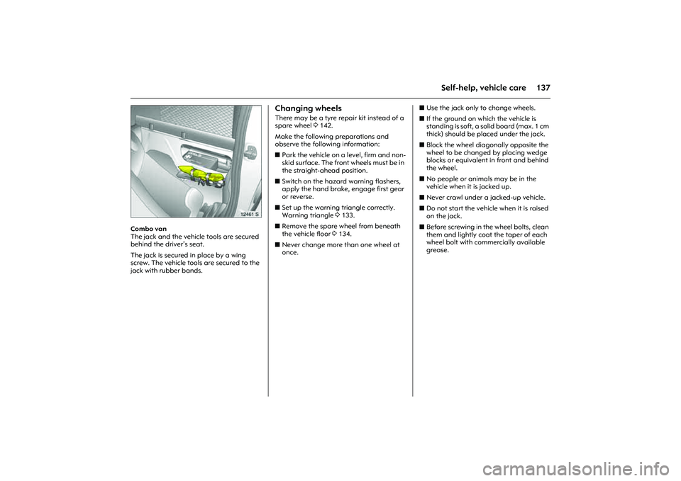
Combo van
The jack and the vehicle tools are secured
behind the driver’s seat.
The jack is secured in place by a wing
screw. The vehicle tools are secured to the
jack with rubber bands.
Changing wheels There may be a tyre repair kit instead of a
spare wheel 3142.
Make the following preparations and
observe the following information:
zPark the vehicle on a level, firm and non-
skid surface. The front wheels must be in
the straight-ahead position.
zSwitch on the hazard warning flashers,
apply the hand brake, engage first gear
or reverse.
zSet up the warning triangle correctly.
Warning triangle 3133.
zRemove the spare wheel from beneath
the vehicle floor 3134.
zNever change more than one wheel at
once. zUse the jack only to change wheels.
zIf the ground on which the vehicle is
standing is soft, a solid board (max. 1 cm
thick) should be placed under the jack.
zBlock the wheel diagonally opposite the
wheel to be changed by placing wedge
blocks or equivalent in front and behind
the wheel.
zNo people or animals may be in the
vehicle when it is jacked up.
zNever crawl under a jacked-up vehicle.
zDo not start the vehicle when it is raised
on the jack.
zBefore screwing in the wheel bolts, clean
them and lightly coat the taper of each
wheel bolt with commercially available
grease.
Page 144 of 212
138 Self-help, vehicle care
Picture no: 12483s.tif
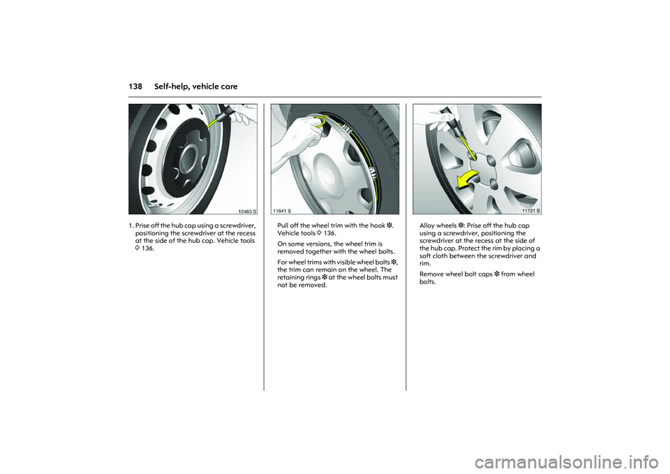
1. Prise off the hub cap using a screwdriver,
positioning the screwdriver at the recess
at the side of the hub cap. Vehicle tools
3136.
Picture no: 11641s.tif
Pull off the wheel trim with the hook 3.
Vehicle tools 3136.
On some versions, the wheel trim is
removed together with the wheel bolts.
For wheel trims with visible wheel bolts 3,
the trim can remain on the wheel. The
retaining rings 3 at the wheel bolts must
not be removed.
Picture no: 11721s.tif
Alloy wheels 3: Prise off the hub cap
using a screwdriver, positioning the
screwdriver at the recess at the side of
the hub cap. Protect the rim by placing a
soft cloth between the screwdriver and
rim.
Remove wheel bolt caps 3 from wheel
bolts.
Page 145 of 212
139
Self-help, vehicle care
Picture no: 11642s.tif
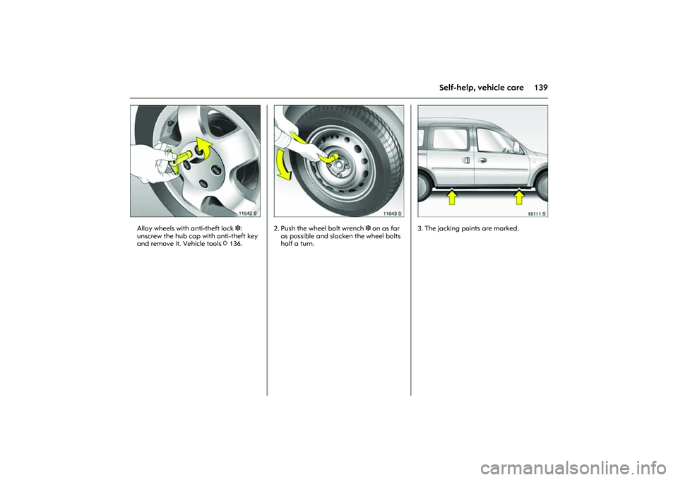
Alloy wheels with anti-theft lock3:
unscrew the hub cap with anti-theft key
and remove it. Vehicle tools 3136.
Picture no: 11643s.tif
2. Push the wheel bolt wrench 3 on as far
as possible and slacken the wheel bolts
half a turn.
Picture no: 18111s.tif
3. The jacking points are marked.
Page 146 of 212
140 Self-help, vehicle care
Picture no: 11645s.tif
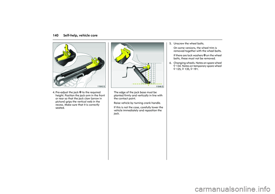
4. Pre-adjust the jack 3 to the required
height. Position the jack arm in the front
or rear so that the jack claw (arrow in
picture) grips the vertical web in the
recess. Make sure that it is correctly
seated.
Picture no: 11646s.tif
The edge of the jack base must be
planted firmly and vertically in line with
the contact point.
Raise vehicle by turning crank handle.
If this is not the case, carefully lower the
vehicle immediately and reposition the
jack.5. Unscrew the wheel bolts.
On some versions, the wheel trim is
removed together with the wheel bolts.
If there are lock washers 3 on the wheel
bolts, these must not be removed.
6. Changing wheels. Notes on spare wheel
3134. Notes on temporary spare wheel
3125, 3135, 3191.
Page 147 of 212
141
Self-help, vehicle care
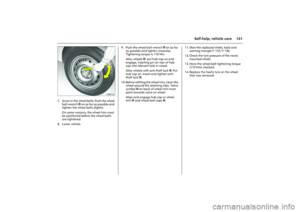
Picture no: 11647s.tif
7. Screw in the wheel bolts. Push the wheel
bolt wrench 3 on as far as possible and
tighten the wheel bolts slightly.
On some versions, the wheel trim must
be positioned before the wheel bolts
are tightened.
8. Lower vehicle. 9. Push the wheel bolt wrench 3 on as far
as possible and tighten crosswise.
Tightening torque is 110 Nm.
Alloy wheels 3: put hub cap on and
engage, inserting pin on rear of hub
cap into relevant hole in wheel.
Alloy wheels with anti-theft lock3: Put
hub cap on. Insert and tighten anti-
theft lock3.
10. Before refitting the wheel trim, clean the
wheel around the retaining clips. Valve
symbol 3 on back of wheel trim must
point towards valve on wheel.
Align and engage hub cap or wheel
trim 3 and wheel bolt caps 3.11. Stow the replaced wheel, tools and
warning triangle 3133, 3136.
12. Check the tyre pressure of the newly
mounted wheel.
13. Have the wheel bolt tightening torque
(110 Nm) checked.
14. Replace the faulty tyre on the wheel
that was removed.