oil OPEL FRONTERA 1998 Workshop Manual
[x] Cancel search | Manufacturer: OPEL, Model Year: 1998, Model line: FRONTERA, Model: OPEL FRONTERA 1998Pages: 6000, PDF Size: 97 MB
Page 776 of 6000

4D2–9 TRANSFER CASE (TOD)
Transfer Case
Disassembled View
266RW004
Legend
(1) Front Companion Flange
(2) 4H and 4L Switch, Ground Cable, and Center
Connector
(3) Offset Lever(4) Spring Pin
(5) Transfer Case Assembly
(6) Transfer Cover Assembly
(7) Rear Companion Flange
Disassembly
1. Remove the drain plug from the transfer case and
drain the oil.
2. Disconnect the 4H and 4L switch and ground cable.
3. Remove the clip fixing the harness.
4. Using the flange holder 5-8840-0133-0 (J-8614-11),
remove the flange nut, and remove front companion
flange.
5. Using the flange folder 5-8840-0133-0 (J-8614-11),
remove the flange nut, and remove rear companion
flange.
266RW005
Page 777 of 6000

4D2–10
TRANSFER CASE (TOD)
6. Remove the offset lever set bolt on the right side.
261RW015
7. Remove the offset lever lock spring pin.
NOTE: When removing the spring pin, note the recess
position of the pin.
261RW016
8. Remove the offset lever.
261RW017
9. Remove the sixteen bolts and detach the transfer
cover assembly from the transfer case assembly.
NOTE: When removing the transfer cover assembly, be
careful not to damage the oil seal.
Reassembly
1. Apply liquid gasket (Loctite 598 or equivalent)
uniformly to the mating face that contacts the transfer
case.
261RW023
Page 779 of 6000

4D2–12
TRANSFER CASE (TOD)
Transfer Cover Assembly
Disassembled View
261RW007
Legend
(1) Coil Assembly
(2) Snap Ring
(3) Ball Bearing(4) Speed Gear and Tone Wheel
(5) Ball Bearing
(6) Transfer Cover Assembly
(7) Front and Rear Speed Sensors
Disassembly
1. Using snap ring pliers, remove the snap ring.
261RW047
Page 780 of 6000

4D2–13 TRANSFER CASE (TOD)
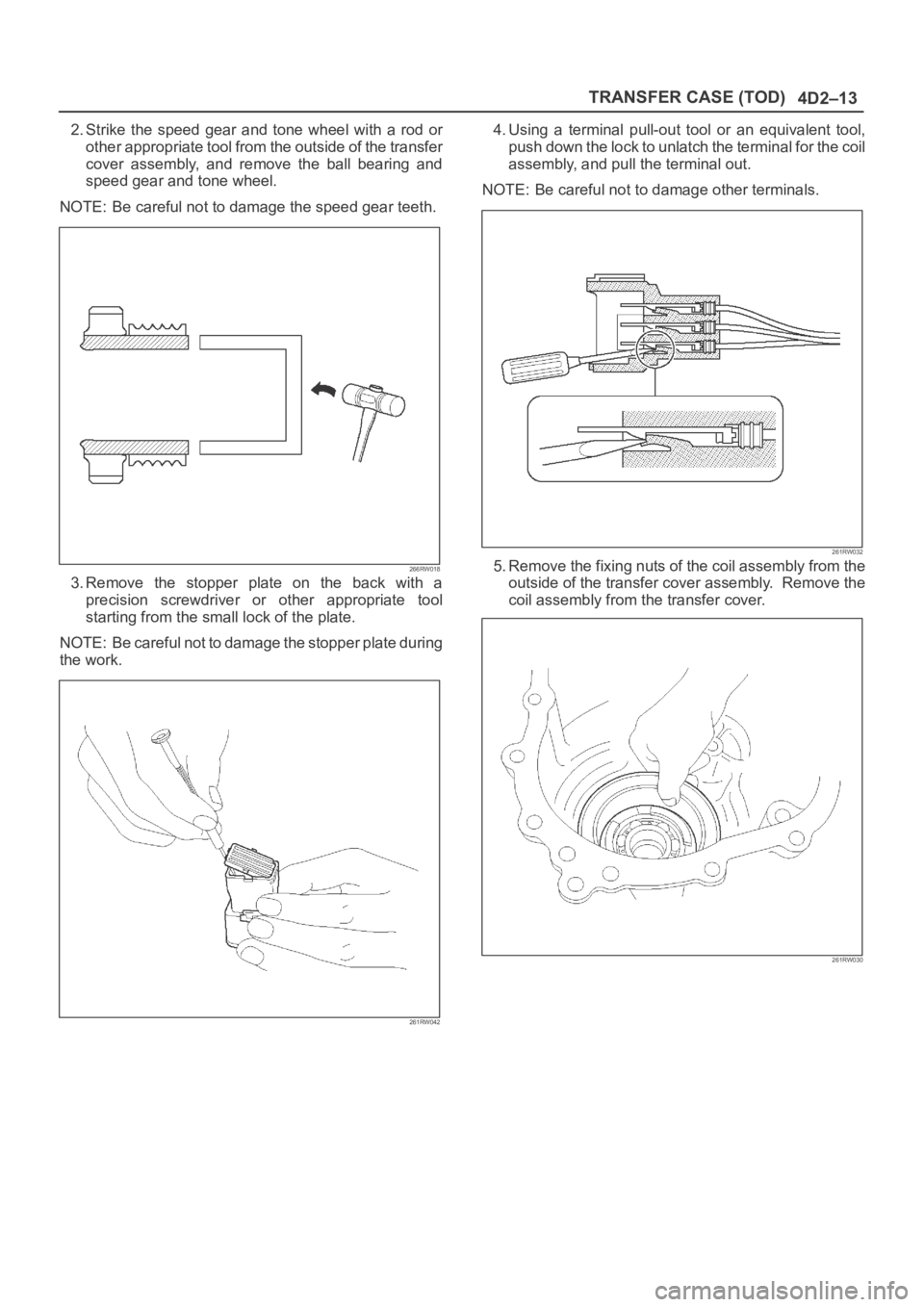
2. Strike the speed gear and tone wheel with a rod or
other appropriate tool from the outside of the transfer
cover assembly, and remove the ball bearing and
speed gear and tone wheel.
NOTE: Be careful not to damage the speed gear teeth.
266RW018
3. Remove the stopper plate on the back with a
precision screwdriver or other appropriate tool
starting from the small lock of the plate.
NOTE: Be careful not to damage the stopper plate during
the work.
261RW042
4. Using a terminal pull-out tool or an equivalent tool,
push down the lock to unlatch the terminal for the coil
assembly, and pull the terminal out.
NOTE: Be careful not to damage other terminals.
261RW032
5. Remove the fixing nuts of the coil assembly from the
outside of the transfer cover assembly. Remove the
coil assembly from the transfer cover.
261RW030
Page 781 of 6000

4D2–14
TRANSFER CASE (TOD)
6. Using the bearing remover 5-8840-2409-0 (J-42805)
and slide hammer 5-8840-0084-0 (J-2619-01),
remove the ball bearing for the front output shaft.
901RW234
7. Remove the bolts and front and rear speed sensors.
NOTE: Be careful not to damage the speed sensors
during the work.
261RW033
Reassembly
1. Remove the oil seal from the transfer cover assembly.
2. Apply oil to the circumference of the new oil seal and
fill the lip with grease (Besco L2 or equivalent).
3. Using the oil seal installer 5-8840-2412-0 (J-42804),
install the oil seal to the transfer cover assembly.
261RW051
Rear Output Shaft Oil Seal
Distance between the transfer case end and oil seal.
NOTE: When installing the oil seal to the specified
dimension, be careful not to damage it.
Dimension : 9.85 — 10.35mm (0.39 — 0.41 in)
A04RW004
Page 782 of 6000

4D2–15 TRANSFER CASE (TOD)
4. Apply a thin coat of grease to the seal ring of each
front and rear speed sensor, and mount the sensors
carefully.
5. Tighten the bolts to the specified torque.
Torque : 5 Nꞏm (0.5 kgꞏm/43 lb in)
NOTE: Pay attention not to mount the front (or rear)
sensor to the rear (or front) sensor position.
6. Install the ball bearing (1) for the front output shaft as
flat as shown in the figure.
261RW008
7. Mount the coil assembly and tighten the nuts to the
specified torque.
Torque : 10 Nꞏm (1.0 kgꞏm/87 lb in)
8. Connect the terminal in the central connector.
NOTE: Be careful not to damage other terminals.
9. Install speed gear and tone wheel.
10. Mount the ball bearing (2) as flat as shown in the
figure.
261RW009–1
11. Using snap ring pliers, install the snap ring to the
transfer cover assembly.NOTE: Securely install the snap ring to the groove of the
transfer cover assembly.
Page 783 of 6000

4D2–16
TRANSFER CASE (TOD)
Transfer Case Assembly Clutch Pack and Clutch Cam
Disassembled View
266RW006
Legend
(1) Clutch Pack Assembly
(2) Insulator Washer
(3) Armature Plate
(4) Snap Ring(5) Wave Spring
(6) Cam Pulley
(7) Cam Ball
(8) Cam and Coil Housing
(9) Thrust Bearing
Disassembly
1. Remove the thrust bearing.
2. Remove the cam and coil housing.
NOTE: When the cam and coil housing is removed, the
cam balls may be detached together with the housing. Be
careful not to lose the ball.
3. Remove the cam ball.
266RW013
Page 785 of 6000

4D2–18
TRANSFER CASE (TOD)
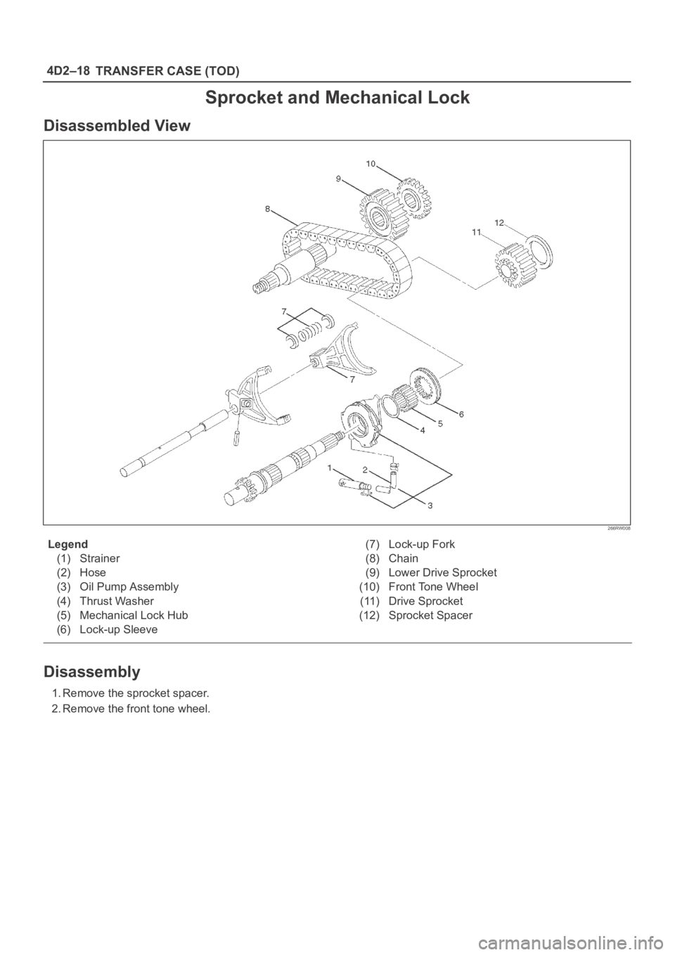
Sprocket and Mechanical Lock
Disassembled View
266RW008
Legend
(1) Strainer
(2) Hose
(3) Oil Pump Assembly
(4) Thrust Washer
(5) Mechanical Lock Hub
(6) Lock-up Sleeve(7) Lock-up Fork
(8) Chain
(9) Lower Drive Sprocket
(10) Front Tone Wheel
(11) Drive Sprocket
(12) Sprocket Spacer
Disassembly
1. Remove the sprocket spacer.
2. Remove the front tone wheel.
Page 786 of 6000

4D2–19 TRANSFER CASE (TOD)
3. Remove the drive sprocket, lower drive sprocket, and
chain together from the front and rear output shafts.
266RW010
4. Remove the mechanical lock hub.
5. Remove the lock-up fork.
6. Remove the spring retainer from the connection
between rail shaft and lock-up fork.
7. Remove the lock-up sleeve.
261RW018
8. Remove the thrust washer.
9. Remove the magnet from the strainer set position
together with the oil pump assembly.
10. Remove the strainer from the oil pump assembly.
11. Remove the hose from the oil pump assembly.
Page 793 of 6000

4D2–26
TRANSFER CASE (TOD)
265RW007
Inspection and Repair
When wear, damage, or any other defects are observed
during the inspection, the part or parts must be repaired or
replaced. Wash all the parts with clean solvent, and
check that old oil, metallic particles, dirt, or foreign
materials are completely removed. Blow the air into oil
holes and grooves to remove foreign materials or residual
detergent.
Chain
Check whether the face that contacts the sprocket is
free from excessive wear or damage. If defects are
observed, replace the part.
If the chain interference mark is found on the inside
w a l l o f t h e t r a n s f e r c o v e r o r t h e c h a i n i s s o s l a c k t h a t a
skipped engagement occurs between the chain and
sprocket, replace the chain.
Sprocket
Check whether the sprocket tooth surface is
excessively worn or damaged, and there is evidence
of burrs, chipping, wear, or damage on the gear
spline. Remove minor flaws or scratches with oil
stone. If excessive wear or damage is observed,
replace the part.
If excessive wear or damage is observed on the
sprocket inside sliding surface, replace the part.
Gear
Check whether the gear tooth surface is excessively
worn or damaged, and there is evidence of burrs,
chipping, wear, or damage on the gear spline.
Remove minor flaws or scratches with oil stone. If
excessive wear or damage is observed, replace the
part.
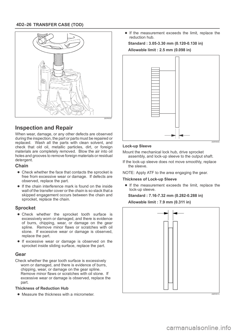
Thickness of Reduction Hub
Measure the thickness with a micrometer.
If the measurement exceeds the limit, replace the
reduction hub.
Standard : 3.05-3.30 mm (0.120-0.130 in)
Allowable limit : 2.5 mm (0.098 in)
265RW005
Lock-up Sleeve
Mount the mechanical lock hub, drive sprocket
assembly, and lock-up sleeve to the output shaft.
If the lock-up sleeve does not move smoothly, replace
the sleeve.
NOTE: Apply ATF to the area engaging the gear.
Thickness of Lock-up Sleeve
If the measurement exceeds the limit, replace the
lock-up sleeve.
Standard : 7.16-7.32 mm (0.282-0.288 in)
Allowable limit : 7.9 mm (0.311 in)
266RW014